EP0252901A2 - Revêtement de protection contre le feu pour poutres en acier de constructions métalliques - Google Patents
Revêtement de protection contre le feu pour poutres en acier de constructions métalliques Download PDFInfo
- Publication number
- EP0252901A2 EP0252901A2 EP87890146A EP87890146A EP0252901A2 EP 0252901 A2 EP0252901 A2 EP 0252901A2 EP 87890146 A EP87890146 A EP 87890146A EP 87890146 A EP87890146 A EP 87890146A EP 0252901 A2 EP0252901 A2 EP 0252901A2
- Authority
- EP
- European Patent Office
- Prior art keywords
- steel
- fire protection
- layer
- cavities
- plasterboard
- Prior art date
- Legal status (The legal status is an assumption and is not a legal conclusion. Google has not performed a legal analysis and makes no representation as to the accuracy of the status listed.)
- Granted
Links
Images

Classifications
-
- E—FIXED CONSTRUCTIONS
- E04—BUILDING
- E04B—GENERAL BUILDING CONSTRUCTIONS; WALLS, e.g. PARTITIONS; ROOFS; FLOORS; CEILINGS; INSULATION OR OTHER PROTECTION OF BUILDINGS
- E04B1/00—Constructions in general; Structures which are not restricted either to walls, e.g. partitions, or floors or ceilings or roofs
- E04B1/62—Insulation or other protection; Elements or use of specified material therefor
- E04B1/92—Protection against other undesired influences or dangers
- E04B1/94—Protection against other undesired influences or dangers against fire
- E04B1/941—Building elements specially adapted therefor
- E04B1/943—Building elements specially adapted therefor elongated
- E04B1/944—Building elements specially adapted therefor elongated covered with fire-proofing material
Definitions
- the invention relates to a fire protection cladding for steel girders of steel structures, which is formed by at least one layer of plasterboard covering the girder or structural part to be protected, which layer is kept free from cavities on these girders or structural parts.
- these flame attachments have the disadvantage of a large expenditure of material, in particular with regard to the gypsum plasterboard, the work involved in the manufacture of the flame attachment of the absolutely necessary three-layer composite for the existing fire regulations, in particular for the class F 90 considerably, and in addition a mechanical fastening by steel strips or wire rope must be carried out, which has the disadvantage in terms of fire technology that these steel strips or wire wires outside heat up considerably in the event of a fire and lead to premature local destruction of the plasterboard.
- the cladding has at least eie further cladding layer made of plasterboard, which is kept clear of closed cavities by spacers at a distance from the first-mentioned cladding layer, the between the carrier or structural part and the first cladding and between this and the further casing formed cavities are closed gas-tight.
- the gas-tight closure of the cavities ensures that no hot flame gases penetrate into the cavities and through the Leakage of the crystal water and its evaporation can reduce the cooling effect as long as the plasterboard layers are not destroyed. Since the latter is only to be expected after a correspondingly long duration of action of a fire on the casing, the construction according to the invention has a correspondingly high fire resistance. This makes it possible to meet the provisions of the relevant safety regulations with a very simple construction.
- the cavities can be kept free by arranging at least spacer elements between the steel support and the first covering layer as well as between the successive further covering layers.
- these measures have the advantage that the gypsum plasterboard can be laid in a particularly simple manner when the flame attachment is erected.
- the cavities can also be kept free according to the invention in that the cladding layers which come into full contact with one another as well as with the steel support are each formed with depressions to form the cavities.
- the plasterboard can be brought into contact with both the steel girder and against each other gives rise to the possibility of particularly rapid processing. According to the recesses, the crystal water can be evaporated freely in the event of a fire.
- the procedure according to the invention is such that the plates of each cladding are largely gas-tightly connected to one another. This ensures that the cooling effect which occurs on the surfaces of the gypsum cardboard casing facing the cavities is not impaired by hot gases from the flame space due to the evaporative cooling.
- Yet another embodiment of the fire protection cladding according to the invention can consist in that a steel beam with an I-shaped cross-section is subdivided into the cavity formed between the first casing and the I-beam by zigzag-shaped, plate-shaped plasterboard blanks.
- Another advantageous embodiment of the fire protection cladding according to the invention can consist in that the outermost cladding layer is formed at least in regions by a space-forming wall plate made of plasterboard. This creates the possibility with regard to the outermost sheathing to avoid separate spacing elements to create the free spaces in the area of the wall plate, so that if the outermost sheathing (wall plate) is destroyed in the event of a fire, there is no direct connection to the subsequent inner sheathing and thus does not automatically destroy or destroy it is damaged by the destruction of the outer casing.
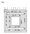
- FIG. 1 shows cross sections through sheathed steel girders according to the invention
- Fig. 3 shows a cross section along line III-III of Fig. 4 through a steel girder with I-shaped cross section installed according to the invention in a wall composite
- Fig. 4 shows a cross section through this structure along line IV-IV of FIG. 3.
- Fig. 1 denotes a steel beam with a hollow profile.
- the invention is not limited to such steel beams. It finds equally advantageous use in solid steel girders or, as will be described in connection with FIG. 2, also in steel girders with an I-shaped cross section.
- Spacer strips 2 are attached to the steel girder, which keep a sheathing, designated overall by 3, from the steel girder.
- This casing 3 consists of a total of four plasterboard 3platten, which are butted together.
- These gypsum plasterboards 3 ⁇ are attached to the reinforced concrete support by arbitrarily distributed, locally limited zones of a commercially available adhesive 4 for gypsum plasterboards.
- cavities 5 are formed between the casing 3 and the steel beam 1, into which the crystal water of the gypsum can evaporate in the event of a fire.
- the spacer elements 2 can be interrupted either continuously or in certain areas. It is not essential for the invention that these spacer elements are provided on all four sides of the steel girder. It only insignificantly complicates the attachment of the casing 3 if such spacer elements are only provided on two opposite sides of the steel girder.
- the covering can have bandages made of a glass fiber fleece or the like, which is fixed to the plasterboard with gypsum mortar. This is indicated by dashed lines at 6 in FIG. 1.
- a sheathing 7 is fixed in the same way, with cavities being kept free, as the sheathing 3 on the steel carrier 1.
- the individual plates are denoted by 7 ⁇ , the other matching parts such as spacer strips and adhesive zones with the same reference numerals.
- the wall thickness of the sheathing plates 3 ⁇ is chosen to be greater than the wall thickness of the sheathing plates 7 ⁇ .
- the wall thicknesses can be selected such that the first sheathing layer with the greatest wall thickness with respect to the steel girder and the subsequent sheathing layers with a relatively smaller, preferably from the inside to the outside, sheathing layer to sheathing layer decreasing wall thickness are formed.
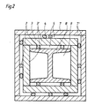
- Fig. 2 shows a fire protection cladding according to the invention for a steel beam with an I-shaped cross section.
- This I-beam is designated 8; 2 has essentially the same structure as the fire protection cladding according to FIG. 1. The same parts are therefore designated by the same reference numerals.
- FIG. 3 and 4 show plan and elevation cross sections of a further possible embodiment of a fire protection cladding according to the invention for a steel beam with an I-shaped cross section.
- the inner casing corresponds to the structure according to FIG. 2 both in terms of its structure and its distance from the steel girder.
- this second cladding is formed on two sides by space-forming plasterboard 11.
- the gypsum plasterboards 12 complement this second casing to form a closed cross section.
- the release of voids between the first casing 3 and the second casing formed by the plates 11 and 12 takes place essentially by means of the spacer elements 13.
- a particularly advantageous embodiment in the case of such fire protection cladding can consist in that the between the plates 11 and the adjacent plates 3 ⁇ of the inner cladding cavities are left completely free of spacer strips and adhesive zones.
- spacer elements 14 can be provided on the end faces of the plates 3 ⁇ of the inner casing running perpendicular to the plates 11. With regard to the spacer elements 14, it is advantageous if they only consist of locally limited spacing areas and not e.g. from continuous strips, which increases the security against damage to this inner casing in the event of destruction of the outer plates 11 in the event of a fire.
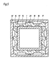
- the cavities according to the invention in the case of fire protection cladding can, according to the exemplary embodiment according to FIG. 5, also be provided in that recesses 17 and 18 are formed in the plates 15 and 16 forming a respective envelope 15 and 16, which recesses can, for example, run like a channel .
- the plates 15 ⁇ and 16 ⁇ formed in this way can be glued firmly to the steel support 1 or to the sheathing underneath, according to the recesses 18 or 19 automatically comes to the formation of cavities according to the invention for the evaporation of the crystal water.
- spacer elements such as 20 can also be used here.
- This exemplary embodiment was explained with the aid of a steel girder with a hollow cross-section, whereby naturally this embodiment can equally be used with steel girders with a full cross-section or with an I-shaped cross-section.
- Unfinished floors or unfinished ceilings are glued with their end faces to these components and, if necessary, even filled. If different wrappings come together, they are glued to one another and, if necessary, filled.
Landscapes
- Engineering & Computer Science (AREA)
- Architecture (AREA)
- Physics & Mathematics (AREA)
- Electromagnetism (AREA)
- Civil Engineering (AREA)
- Structural Engineering (AREA)
- Building Environments (AREA)
- Rod-Shaped Construction Members (AREA)
- Chemical Or Physical Treatment Of Fibers (AREA)
Applications Claiming Priority (2)
| Application Number | Priority Date | Filing Date | Title |
|---|---|---|---|
| AT0183686A AT386235B (de) | 1986-07-07 | 1986-07-07 | Brandschutzverkleidung fuer stahltraeger von stahlkonstruktionen |
| AT1836/86 | 1986-07-07 |
Publications (3)
| Publication Number | Publication Date |
|---|---|
| EP0252901A2 true EP0252901A2 (fr) | 1988-01-13 |
| EP0252901A3 EP0252901A3 (en) | 1988-07-06 |
| EP0252901B1 EP0252901B1 (fr) | 1992-05-13 |
Family
ID=3522063
Family Applications (1)
| Application Number | Title | Priority Date | Filing Date |
|---|---|---|---|
| EP87890146A Expired - Lifetime EP0252901B1 (fr) | 1986-07-07 | 1987-07-01 | Revêtement de protection contre le feu pour poutres en acier de constructions métalliques |
Country Status (5)
| Country | Link |
|---|---|
| EP (1) | EP0252901B1 (fr) |
| AT (2) | AT386235B (fr) |
| DE (1) | DE3778984D1 (fr) |
| ES (1) | ES2001011A4 (fr) |
| GR (1) | GR880300059T1 (fr) |
Cited By (3)
| Publication number | Priority date | Publication date | Assignee | Title |
|---|---|---|---|---|
| AU643360B2 (en) * | 1991-02-01 | 1993-11-11 | Boral Australian Gypsum Limited | Structural member |
| EP1008698A3 (fr) * | 1998-12-07 | 2001-08-08 | Gebr. Knauf Westdeutsche Gipswerke | Paroi de doublage ayant des propriétés ignifuges et insonorisantes |
| US6381917B1 (en) * | 1999-09-08 | 2002-05-07 | Inventio Ag | Lift door panel |
Family Cites Families (3)
| Publication number | Priority date | Publication date | Assignee | Title |
|---|---|---|---|---|
| US3217456A (en) * | 1962-10-12 | 1965-11-16 | United States Gypsum Co | Structural member with multi-layered gypsum board fire protection |
| US4480419A (en) * | 1982-06-25 | 1984-11-06 | Crites Robert C | Method for attaching furring adjacent to columns |
| DD226611A1 (de) * | 1984-09-10 | 1985-08-28 | Bauakademie Ddr | Feuerwiderstandsfaehige verkleidung fuer stahl- und holzkonstruktionen |
-
1986
- 1986-07-07 AT AT0183686A patent/AT386235B/de not_active IP Right Cessation
-
1987
- 1987-07-01 AT AT87890146T patent/ATE76142T1/de not_active IP Right Cessation
- 1987-07-01 DE DE8787890146T patent/DE3778984D1/de not_active Expired - Fee Related
- 1987-07-01 EP EP87890146A patent/EP0252901B1/fr not_active Expired - Lifetime
- 1987-07-01 ES ES87890146T patent/ES2001011A4/es active Pending
-
1988
- 1988-05-20 GR GR88300059T patent/GR880300059T1/el unknown
Cited By (3)
| Publication number | Priority date | Publication date | Assignee | Title |
|---|---|---|---|---|
| AU643360B2 (en) * | 1991-02-01 | 1993-11-11 | Boral Australian Gypsum Limited | Structural member |
| EP1008698A3 (fr) * | 1998-12-07 | 2001-08-08 | Gebr. Knauf Westdeutsche Gipswerke | Paroi de doublage ayant des propriétés ignifuges et insonorisantes |
| US6381917B1 (en) * | 1999-09-08 | 2002-05-07 | Inventio Ag | Lift door panel |
Also Published As
| Publication number | Publication date |
|---|---|
| EP0252901A3 (en) | 1988-07-06 |
| DE3778984D1 (de) | 1992-06-17 |
| EP0252901B1 (fr) | 1992-05-13 |
| GR880300059T1 (en) | 1988-10-18 |
| ATA183686A (de) | 1987-12-15 |
| AT386235B (de) | 1988-07-25 |
| ES2001011A4 (es) | 1988-04-16 |
| ATE76142T1 (de) | 1992-05-15 |
Similar Documents
| Publication | Publication Date | Title |
|---|---|---|
| AT511220A1 (de) | Deckenelement zur ausbildung von gebäudedecken | |
| DE19818525A1 (de) | Holz-Beton-Verbundelement | |
| CH617486A5 (en) | Fire-resistant lightweight partition wall for inner rooms of buildings | |
| EP0023042B1 (fr) | Elément de plancher préfabriqué pour planchers de bâtiments | |
| DE9000975U1 (de) | Rahmen für Durchführung von Leitungen durch ein Bauteil | |
| EP1482101A1 (fr) | Elément de construction, procédé pour fabriquer des éléments de construction et moyens de liaison pour élément de construction | |
| DE4421839C1 (de) | Schalungstafel aus Beton | |
| EP0252901B1 (fr) | Revêtement de protection contre le feu pour poutres en acier de constructions métalliques | |
| DE875403C (de) | Bauelement und Verfahren zu seiner Herstellung | |
| EP0947638A2 (fr) | Panneau d'isolation pour façades extérieures de maisons | |
| DE2737585C2 (de) | Feuerhemmende Trennwand | |
| DE2345173A1 (de) | Bausatz fuer eine deckenkonstruktion | |
| EP0562589B1 (fr) | Elément de coffrage en matière synthétique dure en mousse pour le procédé de construction en béton, dit à manteau | |
| DE3210928C2 (de) | I-förmiger Träger | |
| DE606167C (de) | Hohlwand oder Decke aus Platten, vorzugsweise Korksteinplatten | |
| DE20219304U1 (de) | Leicht-Hochlochziegel | |
| DE2219202A1 (de) | Verfahren zum herstellen von mehrgeschossigen bauten aus raumzellen | |
| AT377302B (de) | Vorgefertigtes bauelement fuer decken, daecher oder waende | |
| EP0775785A1 (fr) | Brique perforée légère | |
| DE9400103U1 (de) | Mauerstein | |
| EP0796961A1 (fr) | Système d'armature pour éléments en béton cellulaire | |
| DE4341440C2 (de) | Ziegelstein | |
| DE3933392A1 (de) | Selbsttragende aufgeloeste bauplatte | |
| DE2251487A1 (de) | Ein- oder mehrfeldriges brueckentragwerk aus spannbetonbalken | |
| AT396805B (de) | Bauelement |
Legal Events
| Date | Code | Title | Description |
|---|---|---|---|
| PUAI | Public reference made under article 153(3) epc to a published international application that has entered the european phase |
Free format text: ORIGINAL CODE: 0009012 |
|
| AK | Designated contracting states |
Kind code of ref document: A2 Designated state(s): AT BE CH DE ES FR GB GR IT LI LU NL SE |
|
| ITCL | It: translation for ep claims filed |
Representative=s name: ING. VITTORIO LUNATI |
|
| EL | Fr: translation of claims filed | ||
| TCNL | Nl: translation of patent claims filed | ||
| GBC | Gb: translation of claims filed (gb section 78(7)/1977) | ||
| PUAL | Search report despatched |
Free format text: ORIGINAL CODE: 0009013 |
|
| AK | Designated contracting states |
Kind code of ref document: A3 Designated state(s): AT BE CH DE ES FR GB GR IT LI LU NL SE |
|
| 17P | Request for examination filed |
Effective date: 19881209 |
|
| 17Q | First examination report despatched |
Effective date: 19900222 |
|
| GRAA | (expected) grant |
Free format text: ORIGINAL CODE: 0009210 |
|
| AK | Designated contracting states |
Kind code of ref document: B1 Designated state(s): AT BE CH DE ES FR GB GR IT LI LU NL SE |
|
| PG25 | Lapsed in a contracting state [announced via postgrant information from national office to epo] |
Ref country code: GR Free format text: LAPSE BECAUSE OF FAILURE TO SUBMIT A TRANSLATION OF THE DESCRIPTION OR TO PAY THE FEE WITHIN THE PRESCRIBED TIME-LIMIT Effective date: 19920513 Ref country code: SE Effective date: 19920513 Ref country code: NL Effective date: 19920513 Ref country code: FR Effective date: 19920513 Ref country code: IT Free format text: LAPSE BECAUSE OF FAILURE TO SUBMIT A TRANSLATION OF THE DESCRIPTION OR TO PAY THE FEE WITHIN THE PRE;WARNING: LAPSES OF ITALIAN PATENTS WITH EFFECTIVE DATE BEFORE 2007 MAY HAVE OCCURRED AT ANY TIME BEFORE 2007. THE CORRECT EFFECTIVE DATE MAY BE DIFFERENT FROM THE ONE RECORDED.SCRIBED TIME-LIMIT Effective date: 19920513 Ref country code: GB Effective date: 19920513 Ref country code: BE Effective date: 19920513 |
|
| REF | Corresponds to: |
Ref document number: 76142 Country of ref document: AT Date of ref document: 19920515 Kind code of ref document: T |
|
| REF | Corresponds to: |
Ref document number: 3778984 Country of ref document: DE Date of ref document: 19920617 |
|
| PG25 | Lapsed in a contracting state [announced via postgrant information from national office to epo] |
Ref country code: LU Free format text: LAPSE BECAUSE OF NON-PAYMENT OF DUE FEES Effective date: 19920731 Ref country code: LI Effective date: 19920731 Ref country code: CH Effective date: 19920731 |
|
| PG25 | Lapsed in a contracting state [announced via postgrant information from national office to epo] |
Ref country code: ES Free format text: LAPSE BECAUSE OF FAILURE TO SUBMIT A TRANSLATION OF THE DESCRIPTION OR TO PAY THE FEE WITHIN THE PRESCRIBED TIME-LIMIT Effective date: 19920824 |
|
| EN | Fr: translation not filed | ||
| NLV1 | Nl: lapsed or annulled due to failure to fulfill the requirements of art. 29p and 29m of the patents act | ||
| GBV | Gb: ep patent (uk) treated as always having been void in accordance with gb section 77(7)/1977 [no translation filed] | ||
| PLBE | No opposition filed within time limit |
Free format text: ORIGINAL CODE: 0009261 |
|
| STAA | Information on the status of an ep patent application or granted ep patent |
Free format text: STATUS: NO OPPOSITION FILED WITHIN TIME LIMIT |
|
| REG | Reference to a national code |
Ref country code: CH Ref legal event code: PL |
|
| 26N | No opposition filed | ||
| PGFP | Annual fee paid to national office [announced via postgrant information from national office to epo] |
Ref country code: AT Payment date: 19940731 Year of fee payment: 8 |
|
| PGFP | Annual fee paid to national office [announced via postgrant information from national office to epo] |
Ref country code: DE Payment date: 19940922 Year of fee payment: 8 |
|
| PG25 | Lapsed in a contracting state [announced via postgrant information from national office to epo] |
Ref country code: AT Effective date: 19950701 |
|
| PG25 | Lapsed in a contracting state [announced via postgrant information from national office to epo] |
Ref country code: DE Effective date: 19960402 |