EP0252936B1 - Vorrichtung zum abheben von bogenpaketen, insbesondere von papier, von stapeln - Google Patents
Vorrichtung zum abheben von bogenpaketen, insbesondere von papier, von stapeln Download PDFInfo
- Publication number
- EP0252936B1 EP0252936B1 EP19870900179 EP87900179A EP0252936B1 EP 0252936 B1 EP0252936 B1 EP 0252936B1 EP 19870900179 EP19870900179 EP 19870900179 EP 87900179 A EP87900179 A EP 87900179A EP 0252936 B1 EP0252936 B1 EP 0252936B1
- Authority
- EP
- European Patent Office
- Prior art keywords
- stack
- sheets
- bundle
- separator element
- bundles
- Prior art date
- Legal status (The legal status is an assumption and is not a legal conclusion. Google has not performed a legal analysis and makes no representation as to the accuracy of the status listed.)
- Expired - Lifetime
Links
- 238000006073 displacement reaction Methods 0.000 claims description 8
- 238000001514 detection method Methods 0.000 claims description 5
- 230000002441 reversible effect Effects 0.000 claims description 5
- 230000000284 resting effect Effects 0.000 claims description 4
- 238000000926 separation method Methods 0.000 abstract description 3
- 230000003100 immobilizing effect Effects 0.000 description 2
- 240000008042 Zea mays Species 0.000 description 1
- 230000000903 blocking effect Effects 0.000 description 1
- KUNSUQLRTQLHQQ-UHFFFAOYSA-N copper tin Chemical group [Cu].[Sn] KUNSUQLRTQLHQQ-UHFFFAOYSA-N 0.000 description 1
- 238000000151 deposition Methods 0.000 description 1
- 230000005284 excitation Effects 0.000 description 1
- 230000005415 magnetization Effects 0.000 description 1
- 239000000463 material Substances 0.000 description 1
- 230000003252 repetitive effect Effects 0.000 description 1
Images


Classifications
-
- B—PERFORMING OPERATIONS; TRANSPORTING
- B65—CONVEYING; PACKING; STORING; HANDLING THIN OR FILAMENTARY MATERIAL
- B65H—HANDLING THIN OR FILAMENTARY MATERIAL, e.g. SHEETS, WEBS, CABLES
- B65H3/00—Separating articles from piles
- B65H3/32—Separating articles from piles by elements, e.g. fingers, plates, rollers, inserted or traversed between articles to be separated and remainder of the pile
- B65H3/322—Separating articles from piles by elements, e.g. fingers, plates, rollers, inserted or traversed between articles to be separated and remainder of the pile for separating a part of the pile, i.e. several articles at once
- B65H3/327—Separating articles from piles by elements, e.g. fingers, plates, rollers, inserted or traversed between articles to be separated and remainder of the pile for separating a part of the pile, i.e. several articles at once the pile being off-set
-
- B—PERFORMING OPERATIONS; TRANSPORTING
- B65—CONVEYING; PACKING; STORING; HANDLING THIN OR FILAMENTARY MATERIAL
- B65H—HANDLING THIN OR FILAMENTARY MATERIAL, e.g. SHEETS, WEBS, CABLES
- B65H2301/00—Handling processes for sheets or webs
- B65H2301/40—Type of handling process
- B65H2301/42—Piling, depiling, handling piles
- B65H2301/422—Handling piles, sets or stacks of articles
-
- B—PERFORMING OPERATIONS; TRANSPORTING
- B65—CONVEYING; PACKING; STORING; HANDLING THIN OR FILAMENTARY MATERIAL
- B65H—HANDLING THIN OR FILAMENTARY MATERIAL, e.g. SHEETS, WEBS, CABLES
- B65H2301/00—Handling processes for sheets or webs
- B65H2301/40—Type of handling process
- B65H2301/42—Piling, depiling, handling piles
- B65H2301/423—Depiling; Separating articles from a pile
- B65H2301/4232—Depiling; Separating articles from a pile of horizontal or inclined articles, i.e. wherein articles support fully or in part the mass of other articles in the piles
- B65H2301/42324—Depiling; Separating articles from a pile of horizontal or inclined articles, i.e. wherein articles support fully or in part the mass of other articles in the piles from top of the pile
-
- B—PERFORMING OPERATIONS; TRANSPORTING
- B65—CONVEYING; PACKING; STORING; HANDLING THIN OR FILAMENTARY MATERIAL
- B65H—HANDLING THIN OR FILAMENTARY MATERIAL, e.g. SHEETS, WEBS, CABLES
- B65H2701/00—Handled material; Storage means
- B65H2701/10—Handled articles or webs
- B65H2701/18—Form of handled article or web
- B65H2701/182—Piled package
- B65H2701/1826—Arrangement of sheets
- B65H2701/18265—Ordered set of batches of articles
- B65H2701/18266—Ordered set of batches of articles wherein the batches are offset from each other, e.g. stepped pile
Definitions
- the invention relates to a device for separating packets of sheets, in particular sheets of paper, forming a stack in which the packets are alternately offset on one side and then on the other, so as to each have a free margin d on either side of the stack.
- sheets of paper constituting a book, a brochure, etc. to be stacked one on top of the other at the exit of a fast printer (for example a laser printer) by forming a stack comprising a certain number of books or brochures which differ from each other by their number of sheets and by their printed texts.
- a fast printer for example a laser printer
- the sheets constituting a book are exactly superimposed, while the books are offset laterally alternately with respect to each other, each book thus having, on one side or the other of the stack, a margin free which protrudes from the immediately lower book.
- This offset allows an operator to enter the books one by one by their free margin to introduce them into a binding machine.
- the subject of the invention is a machine capable of automatically carrying out this task, in a safe and reliable manner, at a rate which corresponds at least to the rate of work of an automatic binding machine and is much higher than the rate of an operator.
- the invention provides a device for separating packets of sheets, in particular of paper, forming a stack in which the packets are alternately offset on one side, then on the other, so as to each have a free margin. on one side or the other of the stack, characterized in that it comprises a lifting table carrying the stack of packets of sheets, a separating element displaceable between the packets of sheets, guide means and displacement means of the separating element making it possible to position it on the free margin of the packet situated immediately below the upper packet of the stack, to engage it under the lower sheet of this upper packet and to move it towards the free margin of the upper packet by lifting at least one edge of this upper pack, means for picking up this upper pack by its raised edge and for transporting this pack away from the stack, and means for detecting on and positioning in height, relative to the means for guiding the separating element, of the free margin of the packet situated immediately below the upper packet of the stack.
- This device therefore makes it possible to separate the different packets of sheets forming a stack from one another, to take each packet and to transport it away from the stack, for example to a binding machine.
- the separating element is an annular or cylindrical brush of horizontal axis, driven in rotation around this axis by reversible motor means, the direction of rotation of the brush being such that it tends lifting the leaves of a packet when the brush engages the edge of this packet, control means being provided to stop the rotation of the brush when the upper packet is taken from the pile and then reverse the direction of rotation of the brush for separating the next package.
- This separating element makes it possible to very quickly lift all the leaves of a given package, without damaging them.
- the detection means comprise two flaps mounted to pivot each around a horizontal axis on one side and the other of the stack, the ends of these flaps coming to bear, respectively, on the free margin of the upper packet of the stack and on that of the immediately lower packet, and the means for guiding the separating element comprise a ramp extending between the two flaps along an edge of the stack and on which rests the separating element.
- the detection means such as for example a photoelectric cell, detect the angular position of each flap relative to its pivot axis, and are connected to means for controlling the height movement of the lifting table, forming part of the aforementioned positioning means.
- the packets of sheets are stacked on a support plate which rests on centering rollers provided on the upper face of the lifting table, which also comprises means for immobilizing the support plate, such for example that an electromagnet.
- This arrangement makes it possible to center the stack of packets of sheets on the lifting table, and therefore to position it correctly with respect to the separating element and its guide means.
- this support plate forms the movable bottom of a magazine supplying this device with stacks of packets of sheets, this magazine forming part of a turntable comprising several identical magazines.
- Such a store allows the automatic feeding of the device according to the invention into stacks of sheet packets and, moreover, constitutes a buffer zone for storing sheet packets between the output of the printer and a binding machine.
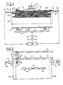
- FIGS. 1 to 3 representing the device according to the invention, associated with a turntable for feeding stacks of packets of printed sheets.
- the turntable 10 for example circular in shape, comprises a number of magazines 12 and is rotated about a vertical central axis by motor means 14 to bring each of its magazines opposite a lifting table 16.
- Each store 12 comprises a removable plate 18 covering an opening 20 of the plate 10 at the four corners of which are fixed vertical angles 22 delimiting a zone for receiving packets of printed sheets.
- Each plate 18 has dimensions slightly greater than those of an opening 20 of the plate 10, so as to be able to rest at its ends on the edges of the opening, the corners of the plate 18 being indented, as shown, to allow the passage of the vertical angles 22.
- Each opening 20 has on the other hand dimensions slightly larger than those of the lifting table 16, so that the latter, placed under a plate 18 forming an opening 20, can rise and pass through the opening 20 for lifting the plate 18 and the bundles of sheets stacked on this plate between the angles 22.
- the actual device for separating the packets of sheets comprises the lifting table 16, means 24, for example with an electric motor, for moving the table 16 vertically two movable side plates 26 suitable for being applied on two opposite vertical sides of the stack of sheet packets, a fixed vertical plate 28 forming a guide for another side of the stack of sheet packs, the upper edge of this plate 28 forming a ramp or guide cam moving a separating element 30 packets of sheets, means 32 for moving the separating element 30 in reciprocating movement on the upper edge of the fixed plate 28, and a clamp 34 for gripping a packet of sheets and depositing this packet of sheets on a conveyor means 36 taking the package of sheets, for example to a binding machine. All of these will be described in detail in the following.
- a stack of bundles of sheets carried by a plate 18 of a magazine 12 is formed of bundles 40 of sheets which are placed on top of each other, and which are formed of sheets of paper having the same dimensions, the sheets of a packet 40 being exactly superimposed on each other, while the packets 40 are alternately offset on one side and the other of the stack (on the left side and on the right side in Figure 3) so that each packet 40 has a free margin 42 which protrudes from one side or the other of the packet 40 immediately below. It can be seen that the packets of sheets 40 are alternately offset from one side or the other in a single horizontal direction, while their edges are exactly aligned in the perpendicular horizontal direction.
- the distance between two angles 22 located along a long side of an opening 20 of the plate 10 is equal to the length of a sheet of paper increased by the desired length of the free margin (by example 10 mm), while the distance between two angles 22 located along a short side of the opening 20 is substantially equal to the width of the sheets of paper.
- the lifting table 16 carries, on its upper face, rollers 44 rotatably mounted around horizontal axes perpendicular to the direction of offset of the packets of sheets 40 on a support plate 18 which rests on these rollers 44 and can therefore be moved in one way or the other parallel to this direction.
- the lifting table 16 further comprises means 46 for immobilizing a support plate 18 placed on the rollers 44, these means 46 may be constituted by an electromagnet when the support plate 18 is made of material capable of magnetization, the excitation electromagnet resulting in blockage; by magnetic attraction, of the support plate 18.
- the movable side plates 26 are either fixed or displaceable in height with the lifting table 16 and are moreover associated with displacement means in the two directions indicated by the arrows 48 in FIG. 2 so as to come to be applied on both sides of the stack of sheet packets which are formed by the free margins 42 of these sheet packs in order to center the support plate 18 and the stack of sheet packs on the lifting table 16 when the blocking means 46 is out of service.
- the plates 26 can be rotatably mounted each around two perpendicular horizontal axes 50 and 52, which are respectively parallel to the sides of a stack of bundles of sheets carried by the lifting table 16, by means, example of pneumatic cylinders 54 and 56, being provided to pivot the plates 26 around the axes 50 and 52 and therefore to move them in the two directions indicated by the arrows 48 in FIG. 2.
- the corresponding sides of the support plate 18 can be scalloped, as shown at 58 in FIG. 2, to receive the lower ends of the side plates 26 which come to apply on the free margins 42 of the packages of sheets resting on the support plate 18.
- a cutout 17 is formed in each of the two corresponding edges of the table 16.
- the separating element 30 which is guided in reciprocating movement on the upper edge of the fixed plate 28, is here constituted by an annular or cylindrical brush 60 with a horizontal axis, which is driven in rotation around this axis by the shaft of output 62 of a reversible electric motor 64 (see FIG. 5).
- the output shaft 62 of the motor 64 extends perpendicularly to the plate 28 and can be provided with any suitable means, for example a bronze ring, for its displacement in reciprocating motion on the upper edge of the plate 28.
- the means 32 for moving the separating element 30 comprise a reversible electric motor, the output shaft of which is connected by an articulated linkage 66, 68, to the motor 64 for driving the brush 60 in rotation.
- the upper edge of the fixed plate 28, forming the guide ramp of the separating element 30, comprises two flat end parts 70, situated at the same height, and a raised flat central part 72, connected to the flat end parts by planes inclined 74.
- the lifting table 16 is associated with means for controlling the movement in height, making it possible to position the separation plane of the upper pack of a stack at the desired height relative to the separating element 30.
- These means comprise two flaps 76 placed on either side of a stack of sheet packets in order to be able to cooperate with the free margins of the sheet packets of the stack and which are each mounted to pivot about a horizontal axis 78 perpendicular to the direction of offset of the packets of sheets sheets in the stack, so that one end of a flap 76 rests on the free margin of the upper pack of the stack while one end of the other flap 76 rests on the free margin of the immediately lower pack of the battery, the opposite ends of the two flaps 76 each extending between the emitting element and the receiving element of a photoelectric cell 80 to conceal or unmask the receiving element d e the photoelectric cell as a function of the angular position of the flap relative to the axis 78.
- the two photoelectric cells 80 are connected to a circuit 82 for
- the device also comprises means 84 (FIG. 1) for moving and actuating the clamp 34, making it possible to move this clamp in rotation about a horizontal axis to come and take a bundle of sheets from the stack carried by the lifting table , to clamp the two jaws of the clamp on this pack of sheets and to move the clamp and the pack of sheets towards the means 36 of transport.
- means 84 for moving and actuating the clamp 34, making it possible to move this clamp in rotation about a horizontal axis to come and take a bundle of sheets from the stack carried by the lifting table , to clamp the two jaws of the clamp on this pack of sheets and to move the clamp and the pack of sheets towards the means 36 of transport.
- a series of rollers 86 are also provided, carried by a horizontal rod 88 which is resiliently biased downwards so as to apply the rollers 86 substantially on the longitudinal axis of the upper face of the upper pack of a stack carried by the lifting table 16.
- the support plate 18 is advantageously curved in the portion of a cylinder, so as to present two parallel straight edges connected to each other by two curved edges in an arc of a circle, the concavity of the support plate 18 being oriented upwards, the plate 18 being carried by the lifting table 16 so that one of its straight edges, located on the side of the fixed plate 28, is at a level lower than that of the other straight edge so that the packets of sheets 40 are correctly applied against the fixed guide plate 28.
- the device which has just been described operates in the following manner.
- the packets of printed sheets constituting books or the like are deposited on the plates 18 of the magazines 12 of the turntable 10, being offset alternately on one side and on the other as already described, so as to each present a free margin d 'about 10 mm protruding from the immediately lower bundle, the overlapping bundles of sheets not necessarily comprising the same number of sheets.
- a magazine 12 By rotating a fraction of a turn of the turntable 10, a magazine 12 is brought filled with bundles of sheets opposite the lift table 16 which is then at a level lower than that of the tray 10. Of course, the side plates 26 have been discarded so as not to be in the path of the magazine 22.
- the table 16 is raised to lift the plate 18 carrying the stack of sheets packets slightly above the tray 10, the side plates 26 are brought back to be applied on the two sides of the stack sheet bundles, as shown in Figures 1 to 3, and thus center the support plate 18 on the lifting table 16, after which the means 46 for locking the support plate 18 is energized to prevent any further displacement of this plate 18 with respect to the lifting table 16.
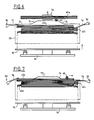
- the lifting of the lifting table 16 continues until the position shown in FIG. 4, in which the flap 76 located on the right side in FIG. 4 is inclined upward relative to the horizontal , its end resting on the free margin of the upper packet 40a of the stack, its opposite end then being located below the associated cell 80, and the flap 76 located on the left side in FIG.
- the separating element 30 is on the left side of the stack in FIG. 4, the brush 60 being on the flap 76, and begins to move to the right 'the brush 60 being driven in rotation at high speed in meaning indicated by arrow 90, that is to say anti-clockwise in FIG. 4.
- the brush 60 will therefore attack the edge of the upper packet 40a which is opposite its free margin and will therefore lift all the sheets of the upper package 40a and move between the raised edge of the upper package and the upper sheet of the lower package 40b as shown in FIG. 4.
- the separating element 30 therefore moves on the horizontal end 70 of the left of the upper edge of the fixed plate 28, climbs the inclined plane 74 and traverses the raised middle part 72 of the upper edge of the plate 28 to stop at the end of this middle part as shown in FIG. 6.
- the flap 76 on the left in FIG. 6 remains pressed on the free margin of the immediately lower pack 40b, while the flap 76 on the right tilts down to come to bear on the free margin of the lower pack 40c which is shifted to the right.
- the rear end of the flap 76 masks the receiver element of the associated cell 80, which results in a rise signal from the lifting table 16 which continues until the flap 76 of right returns to a substantially horizontal position shown in FIG. 7, where its rear end has just unmasked the receiving element of the associated cell 80.
- the separating element 30 resumes its movement to the right from the position shown in FIG. 6, descends on the inclined plane 74 and continues its movement until the brush 60 is located on the part-flap 76 which is supported on the free margin of the package 40c.
- the separating element 30 is moved in the opposite direction, that is to say to the left in FIG. 7, and the brush 60 is rotated at high speed clockwise, to attack the edge of the upper packet 40b which is opposite its free margin.
- the brush 60 lifts the sheets of the upper pack 40b and moves to the left end of the raised middle part 72 of the upper edge of the fixed plate 28, the pliers 34 grips the raised edge of the pack 40b and takes this pack towards the conveyor means 36.
- the flap 76 on the left in FIG. 7 swings down and comes to rest on the free margin of the package 40d located immediately below the package 40c.
- the receiving element of the cell 80 associated with this flap is masked by the rear part of this flap, which results in a rise signal from the lifting table 16 until the flap 76 on the left is again in substantially horizontal position. We then find our in the situation represented in FIG. 4.
- the packets of sheets 40 forming a stack carried by the lifting table 16 are thus separated and taken one after the other to the conveyor means 36.
- the lifting table 16 goes down again, deposits the plate 18 on the edges of the corresponding opening 20 of the turntable 10, and the latter is rotated by a fraction of a turn to bring the next magazine above the lifting table 16.
- the device according to the invention also comprises means, shown in FIG. 1, which make it possible to lift the separating element 30 above the upper edge of the fixed plate 28 and of the upper pack of the stack carried by the lifting table, and this without interrupting the reciprocating movement of this separating element, for example when the means provided downstream of this separation device (conveyor means 36 or binding machine) are stopped.
- These lifting means of the separating element 30 comprise a ramp 92 parallel to the fixed plate 28 and pivotally mounted about a horizontal axis 94 perpendicular to this plate, and a motor means, for example a pneumatic cylinder 96, for movement of the ramp 92 in rotation about the axis 94, between a first position where it is under the separating element 30 and has no action thereon, and a second position where it lifts the element separator 30 above the upper edge of the fixed plate 28.
- a motor means for example a pneumatic cylinder 96
Landscapes
- Engineering & Computer Science (AREA)
- Mechanical Engineering (AREA)
- Forming Counted Batches (AREA)
- Pile Receivers (AREA)
Claims (13)
Priority Applications (1)
| Application Number | Priority Date | Filing Date | Title |
|---|---|---|---|
| AT87900179T ATE52069T1 (de) | 1986-01-03 | 1986-12-31 | Vorrichtung zum abheben von bogenpaketen, insbesondere von papier, von stapeln. |
Applications Claiming Priority (2)
| Application Number | Priority Date | Filing Date | Title |
|---|---|---|---|
| FR8600062A FR2592640B1 (fr) | 1986-01-03 | 1986-01-03 | Dispositif de separation de paquets de feuilles, en particulier de papier, formant une pile |
| FR8600062 | 1986-01-03 |
Publications (2)
| Publication Number | Publication Date |
|---|---|
| EP0252936A1 EP0252936A1 (de) | 1988-01-20 |
| EP0252936B1 true EP0252936B1 (de) | 1990-04-18 |
Family
ID=9330837
Family Applications (1)
| Application Number | Title | Priority Date | Filing Date |
|---|---|---|---|
| EP19870900179 Expired - Lifetime EP0252936B1 (de) | 1986-01-03 | 1986-12-31 | Vorrichtung zum abheben von bogenpaketen, insbesondere von papier, von stapeln |
Country Status (4)
| Country | Link |
|---|---|
| EP (1) | EP0252936B1 (de) |
| DE (1) | DE3670472D1 (de) |
| FR (1) | FR2592640B1 (de) |
| WO (1) | WO1987004141A1 (de) |
Families Citing this family (9)
| Publication number | Priority date | Publication date | Assignee | Title |
|---|---|---|---|---|
| DE3803578A1 (de) * | 1988-02-06 | 1989-08-17 | Minda Industrieanlagen Gmbh | Verfahren fuer die beschickung von stanzen, inline-maschinen o. dgl. mit aus wellpappebogen bestehenden paketen |
| JP2627191B2 (ja) * | 1989-06-26 | 1997-07-02 | 株式会社新川 | リードフレーム分離装置 |
| DE4435921A1 (de) * | 1994-10-07 | 1996-04-11 | Giesecke & Devrient Gmbh | Vorrichtung und Verfahren zur Vereinzelung von in einem Kartenstapel vorliegenden Karten |
| FR2727951B1 (fr) * | 1994-12-13 | 1997-01-17 | Danel Ferry | Dispositif de ramassage et de remplissage de caisses pour documents plats |
| AU6041796A (en) * | 1995-06-07 | 1996-12-30 | Standard Duplicating Machines Corporation | Paper set feeding |
| US6234467B1 (en) * | 1997-11-10 | 2001-05-22 | Kurt Runzi | Apparatus for stacking and sorting printed documents and feeding them to a finishing machine |
| EP1127819A1 (de) * | 2000-02-22 | 2001-08-29 | C.P. Bourg S.A. | Blattstapelzuführvorrichtung |
| WO2002090226A1 (en) * | 2001-05-04 | 2002-11-14 | General Binding Corporation | Paper set feeding apparatus |
| EP2657161B1 (de) * | 2012-04-26 | 2014-06-04 | Hugo Beck Maschinenbau GmbH & Co. KG | Verfahren und Vorrichtung zum automatischen Zuführen von einzelnen Blattstapeln aus einer Druckmaschine in eine Klebebindemaschine |
Family Cites Families (4)
| Publication number | Priority date | Publication date | Assignee | Title |
|---|---|---|---|---|
| DE261039C (de) * | ||||
| US1653305A (en) * | 1926-07-24 | 1927-12-20 | Wayne E Myers | Automatic paper feed |
| US4119219A (en) * | 1977-02-28 | 1978-10-10 | Marquip, Inc. | Batch feeder |
| DE3219693A1 (de) * | 1982-05-26 | 1983-12-01 | Fa. Heinrich Baumann, 6000 Frankfurt | Vorrichtung zur bildung von verarbeitungsfaehigen teilstapeln aus folienbogen, insbesondere papierbogen |
-
1986
- 1986-01-03 FR FR8600062A patent/FR2592640B1/fr not_active Expired
- 1986-12-31 EP EP19870900179 patent/EP0252936B1/de not_active Expired - Lifetime
- 1986-12-31 DE DE8787900179T patent/DE3670472D1/de not_active Expired - Lifetime
- 1986-12-31 WO PCT/FR1986/000452 patent/WO1987004141A1/fr not_active Ceased
Also Published As
| Publication number | Publication date |
|---|---|
| FR2592640A1 (fr) | 1987-07-10 |
| DE3670472D1 (de) | 1990-05-23 |
| WO1987004141A1 (fr) | 1987-07-16 |
| EP0252936A1 (de) | 1988-01-20 |
| FR2592640B1 (fr) | 1988-04-29 |
Similar Documents
| Publication | Publication Date | Title |
|---|---|---|
| EP0122817B1 (de) | Verfahren und Vorrichtung zum automatischen Beschicken einer Maschine zur Behandlung von flachen Gegenständen | |
| FR2499039A1 (fr) | Dispositif pour introduire des paquets de feuilles dans une machine les travaillant | |
| EP0354873A1 (de) | Entpalettierer für Etikettenbündel | |
| FR2537957A1 (fr) | Dispositif de prise et d'entrainement de feuilles pour prendre, transporter et deposer un materiau en feuille | |
| WO2018192685A1 (fr) | Dispositif de recuperation d'echantillons de poses, station d'evacuation et machine de traitement d'elements en forme de feuilles | |
| CH633761A5 (fr) | Dispositif pour empiler des objets plats, notamment des decoupes de boites pliantes. | |
| EP0090123B1 (de) | Vorrichtung zur Handhabung von Packungen, insbesondere von Zigarettenverpackungen | |
| FR2625934A1 (fr) | Systeme pour l'acheminement de pieces estampees | |
| FR2703670A1 (fr) | Assembleuse de feuilles à cases superposées. | |
| WO1987004141A1 (fr) | Dispositif de separation de paquets de feuilles, en particulier de papier, formant une pile | |
| EP0111432A1 (de) | Vorrichtung zur dynamischen Zwischenspeicherung flacher Gegenstände | |
| FR2641769A1 (fr) | Appareil de manutention de feuilles pour agrafage de groupes de feuilles | |
| EP2152439B2 (de) | Teleskoptragevorrichtung für postsendungslagerschächte | |
| FR2680121A1 (fr) | Module empileur pour machine de tri postal ou similaire. | |
| EP0188987B1 (de) | Palettiervorrichtung, insbesondere für Säcke | |
| EP0267431B1 (de) | Einrichtung zum Stapeln von flachen Gegenständen | |
| EP0559553B1 (de) | System zum Handhaben von Gegenständen, insbesondere für selbsttätige Postsortiermaschine | |
| FR2573401A1 (fr) | Procede d'empilage de couches horizontales superposees d'objets sur une palette et installation pour la mise en oeuvre de ce procede | |
| FR2552743A1 (fr) | Machine d'empilage | |
| FR2587311A1 (fr) | Procede et installation de manutention automatique et stockage temporaire de paquets empiles de produits semi-finis en feuilles. | |
| FR2640946A1 (en) | Machine for automatic conveying and destacking of workpieces having a complex shape | |
| FR2789061A1 (fr) | Palettiseur de cahiers imprimes empiles | |
| FR2609458A1 (fr) | Machine de depilage et de convoyage automatiques de pieces, telles que par exemple des flans de tole | |
| FR2609428A1 (fr) | Dispositif d'alimentation d'une presse a partir de deux piles de flans de tole | |
| EP4596469B1 (de) | Stapelvorrichtung zur herstellung von broschüren |
Legal Events
| Date | Code | Title | Description |
|---|---|---|---|
| PUAI | Public reference made under article 153(3) epc to a published international application that has entered the european phase |
Free format text: ORIGINAL CODE: 0009012 |
|
| 17P | Request for examination filed |
Effective date: 19870904 |
|
| AK | Designated contracting states |
Kind code of ref document: A1 Designated state(s): AT BE CH DE FR GB IT LI LU NL SE |
|
| 17Q | First examination report despatched |
Effective date: 19881201 |
|
| GRAA | (expected) grant |
Free format text: ORIGINAL CODE: 0009210 |
|
| AK | Designated contracting states |
Kind code of ref document: B1 Designated state(s): AT BE CH DE FR GB IT LI LU NL SE |
|
| PG25 | Lapsed in a contracting state [announced via postgrant information from national office to epo] |
Ref country code: SE Effective date: 19900418 Ref country code: AT Effective date: 19900418 |
|
| REF | Corresponds to: |
Ref document number: 52069 Country of ref document: AT Date of ref document: 19900515 Kind code of ref document: T |
|
| REF | Corresponds to: |
Ref document number: 3670472 Country of ref document: DE Date of ref document: 19900523 |
|
| ITF | It: translation for a ep patent filed | ||
| GBT | Gb: translation of ep patent filed (gb section 77(6)(a)/1977) | ||
| PLBE | No opposition filed within time limit |
Free format text: ORIGINAL CODE: 0009261 |
|
| STAA | Information on the status of an ep patent application or granted ep patent |
Free format text: STATUS: NO OPPOSITION FILED WITHIN TIME LIMIT |
|
| 26N | No opposition filed | ||
| ITTA | It: last paid annual fee | ||
| EPTA | Lu: last paid annual fee | ||
| PGFP | Annual fee paid to national office [announced via postgrant information from national office to epo] |
Ref country code: BE Payment date: 19941125 Year of fee payment: 9 |
|
| PGFP | Annual fee paid to national office [announced via postgrant information from national office to epo] |
Ref country code: FR Payment date: 19941128 Year of fee payment: 9 |
|
| PGFP | Annual fee paid to national office [announced via postgrant information from national office to epo] |
Ref country code: CH Payment date: 19941202 Year of fee payment: 9 |
|
| PGFP | Annual fee paid to national office [announced via postgrant information from national office to epo] |
Ref country code: GB Payment date: 19941206 Year of fee payment: 9 |
|
| PGFP | Annual fee paid to national office [announced via postgrant information from national office to epo] |
Ref country code: DE Payment date: 19941222 Year of fee payment: 9 |
|
| PGFP | Annual fee paid to national office [announced via postgrant information from national office to epo] |
Ref country code: NL Payment date: 19941231 Year of fee payment: 9 Ref country code: LU Payment date: 19941231 Year of fee payment: 9 |
|
| PG25 | Lapsed in a contracting state [announced via postgrant information from national office to epo] |
Ref country code: LU Free format text: LAPSE BECAUSE OF NON-PAYMENT OF DUE FEES Effective date: 19951231 Ref country code: LI Effective date: 19951231 Ref country code: GB Effective date: 19951231 Ref country code: CH Effective date: 19951231 Ref country code: BE Effective date: 19951231 |
|
| BERE | Be: lapsed |
Owner name: BERTIN & CIE Effective date: 19951231 |
|
| PG25 | Lapsed in a contracting state [announced via postgrant information from national office to epo] |
Ref country code: NL Effective date: 19960701 |
|
| REG | Reference to a national code |
Ref country code: CH Ref legal event code: PL |
|
| GBPC | Gb: european patent ceased through non-payment of renewal fee |
Effective date: 19951231 |
|
| PG25 | Lapsed in a contracting state [announced via postgrant information from national office to epo] |
Ref country code: FR Effective date: 19960830 |
|
| NLV4 | Nl: lapsed or anulled due to non-payment of the annual fee |
Effective date: 19960701 |
|
| PG25 | Lapsed in a contracting state [announced via postgrant information from national office to epo] |
Ref country code: DE Effective date: 19960903 |
|
| REG | Reference to a national code |
Ref country code: FR Ref legal event code: ST |
|
| PG25 | Lapsed in a contracting state [announced via postgrant information from national office to epo] |
Ref country code: IT Free format text: LAPSE BECAUSE OF NON-PAYMENT OF DUE FEES;WARNING: LAPSES OF ITALIAN PATENTS WITH EFFECTIVE DATE BEFORE 2007 MAY HAVE OCCURRED AT ANY TIME BEFORE 2007. THE CORRECT EFFECTIVE DATE MAY BE DIFFERENT FROM THE ONE RECORDED. Effective date: 20051231 |