EP0252996A1 - Dispositif pour le filtrage d'un liquide - Google Patents
Dispositif pour le filtrage d'un liquide Download PDFInfo
- Publication number
- EP0252996A1 EP0252996A1 EP87900741A EP87900741A EP0252996A1 EP 0252996 A1 EP0252996 A1 EP 0252996A1 EP 87900741 A EP87900741 A EP 87900741A EP 87900741 A EP87900741 A EP 87900741A EP 0252996 A1 EP0252996 A1 EP 0252996A1
- Authority
- EP
- European Patent Office
- Prior art keywords
- hose
- housing
- liquid
- residue
- annular space
- Prior art date
- Legal status (The legal status is an assumption and is not a legal conclusion. Google has not performed a legal analysis and makes no representation as to the accuracy of the status listed.)
- Granted
Links
- 239000007788 liquid Substances 0.000 title claims abstract description 42
- 238000001914 filtration Methods 0.000 title claims abstract description 32
- 238000006073 displacement reaction Methods 0.000 claims abstract description 5
- 238000003860 storage Methods 0.000 claims abstract description 4
- 230000001105 regulatory effect Effects 0.000 claims description 2
- 239000012530 fluid Substances 0.000 abstract description 3
- 239000000945 filler Substances 0.000 description 9
- 238000004140 cleaning Methods 0.000 description 5
- 238000000746 purification Methods 0.000 description 5
- 238000010276 construction Methods 0.000 description 4
- 230000009471 action Effects 0.000 description 3
- 238000000034 method Methods 0.000 description 3
- 239000010802 sludge Substances 0.000 description 3
- 239000007787 solid Substances 0.000 description 3
- XEEYBQQBJWHFJM-UHFFFAOYSA-N Iron Chemical compound [Fe] XEEYBQQBJWHFJM-UHFFFAOYSA-N 0.000 description 2
- 230000008878 coupling Effects 0.000 description 2
- 238000010168 coupling process Methods 0.000 description 2
- 238000005859 coupling reaction Methods 0.000 description 2
- 239000003651 drinking water Substances 0.000 description 2
- 235000020188 drinking water Nutrition 0.000 description 2
- 239000010842 industrial wastewater Substances 0.000 description 2
- 244000144972 livestock Species 0.000 description 2
- 239000000463 material Substances 0.000 description 2
- 230000007246 mechanism Effects 0.000 description 2
- 230000008569 process Effects 0.000 description 2
- 238000000926 separation method Methods 0.000 description 2
- 239000010865 sewage Substances 0.000 description 2
- 239000000126 substance Substances 0.000 description 2
- XLYOFNOQVPJJNP-UHFFFAOYSA-N water Substances O XLYOFNOQVPJJNP-UHFFFAOYSA-N 0.000 description 2
- 230000001133 acceleration Effects 0.000 description 1
- 230000001154 acute effect Effects 0.000 description 1
- 238000004026 adhesive bonding Methods 0.000 description 1
- 238000009795 derivation Methods 0.000 description 1
- 239000013013 elastic material Substances 0.000 description 1
- 230000008030 elimination Effects 0.000 description 1
- 238000003379 elimination reaction Methods 0.000 description 1
- 239000000835 fiber Substances 0.000 description 1
- 239000000706 filtrate Substances 0.000 description 1
- 238000007667 floating Methods 0.000 description 1
- 238000011010 flushing procedure Methods 0.000 description 1
- 238000005194 fractionation Methods 0.000 description 1
- 239000011796 hollow space material Substances 0.000 description 1
- 229910052742 iron Inorganic materials 0.000 description 1
- 239000007791 liquid phase Substances 0.000 description 1
- 239000012528 membrane Substances 0.000 description 1
- 238000009856 non-ferrous metallurgy Methods 0.000 description 1
- 238000012856 packing Methods 0.000 description 1
- 239000002245 particle Substances 0.000 description 1
- 238000005192 partition Methods 0.000 description 1
- 230000035515 penetration Effects 0.000 description 1
- 239000000047 product Substances 0.000 description 1
- 230000009467 reduction Effects 0.000 description 1
- 239000004576 sand Substances 0.000 description 1
- 239000007790 solid phase Substances 0.000 description 1
- 239000000725 suspension Substances 0.000 description 1
- 230000000699 topical effect Effects 0.000 description 1
- 239000002351 wastewater Substances 0.000 description 1
Images



Classifications
-
- B—PERFORMING OPERATIONS; TRANSPORTING
- B01—PHYSICAL OR CHEMICAL PROCESSES OR APPARATUS IN GENERAL
- B01D—SEPARATION
- B01D29/00—Filters with filtering elements stationary during filtration, e.g. pressure or suction filters, not covered by groups B01D24/00 - B01D27/00; Filtering elements therefor
- B01D29/11—Filters with filtering elements stationary during filtration, e.g. pressure or suction filters, not covered by groups B01D24/00 - B01D27/00; Filtering elements therefor with bag, cage, hose, tube, sleeve or like filtering elements
- B01D29/13—Supported filter elements
- B01D29/23—Supported filter elements arranged for outward flow filtration
- B01D29/27—Filter bags
-
- B—PERFORMING OPERATIONS; TRANSPORTING
- B01—PHYSICAL OR CHEMICAL PROCESSES OR APPARATUS IN GENERAL
- B01D—SEPARATION
- B01D29/00—Filters with filtering elements stationary during filtration, e.g. pressure or suction filters, not covered by groups B01D24/00 - B01D27/00; Filtering elements therefor
- B01D29/62—Regenerating the filter material in the filter
- B01D29/64—Regenerating the filter material in the filter by scrapers, brushes, nozzles, or the like, acting on the cake side of the filtering element
-
- B—PERFORMING OPERATIONS; TRANSPORTING
- B01—PHYSICAL OR CHEMICAL PROCESSES OR APPARATUS IN GENERAL
- B01D—SEPARATION
- B01D29/00—Filters with filtering elements stationary during filtration, e.g. pressure or suction filters, not covered by groups B01D24/00 - B01D27/00; Filtering elements therefor
- B01D29/62—Regenerating the filter material in the filter
- B01D29/70—Regenerating the filter material in the filter by forces created by movement of the filter element
-
- B—PERFORMING OPERATIONS; TRANSPORTING
- B01—PHYSICAL OR CHEMICAL PROCESSES OR APPARATUS IN GENERAL
- B01D—SEPARATION
- B01D29/00—Filters with filtering elements stationary during filtration, e.g. pressure or suction filters, not covered by groups B01D24/00 - B01D27/00; Filtering elements therefor
- B01D29/88—Filters with filtering elements stationary during filtration, e.g. pressure or suction filters, not covered by groups B01D24/00 - B01D27/00; Filtering elements therefor having feed or discharge devices
- B01D29/90—Filters with filtering elements stationary during filtration, e.g. pressure or suction filters, not covered by groups B01D24/00 - B01D27/00; Filtering elements therefor having feed or discharge devices for feeding
Definitions
- the present invention relates to liquid purification, in particular relates to a periodically operating device for filtering a liquid and can be widely used in the desludging of industrial waste water, the cleaning of sewage outflows by removing solid inclusions, and the circulation and drinking water purification by removing suspensions.
- the invention can be used further in the food industry in the separation of the products into liquid and solid phases, and in water basin and sewer cleaning by separating digested sludge.
- Devices for filtering liquid and gaseous media which have a housing in which a filter element is arranged and which is connected to systems correspondingly for the feed lines of the medium to be filtered, the discharge of the filtrate and the discharge of the residue.
- filter elements of various construction types can be found, e.g. endless belts, sieves, permeable membranes etc. use.
- a periodically acting device for filtering a light fluid medium (a liquid) is known from the SU copyright certificate No. 117 204, IPK B01 D 29/10, 1968, in the housing of which a beige filter element is arranged, which is a flexible bag-shaped container made of filter material, the open end of which is attached to the housing.
- the bottom of the container is fastened to a lifting device via a pull rod, which serves as a means for turning this container in order to remove the filter residue stored therein, so that the container can be displaced relative to its fastening path.
- Such a device is simple in construction, but not very efficient, because the residue stored in the container and the clogging of the filter surface when a portion of filtering liquid is fed into the container make subsequent filtration difficult.
- the container must therefore often be turned over so that the residue can be removed from it, which is time-consuming.
- the invention has for its object to provide a periodically acting device for filtering a liquid, the design of which allows the filter sections of the flexible filter element to be supplied with new sections of the filtering and the surface thereof to be rinsed safely, thereby increasing the filtration performance and easy operation is guaranteed.
- the housing which is connected to systems correspondingly for the supply of the medium to be filtered, the discharge of the cleaned medium and the discharge of the residue, and a flexible filter element, which is designed to be displaceable relative to its fastening path in the housing, contains, according to the invention, the housing is hermetically sealed and a hollow cylinder is arranged therein, which forms an annular space with the housing, which is connected to the residue discharge system, and which bends
- the same filter element consists of a hose, one end of which is attached to a drive drum arranged in the upper part of the housing, which is provided with a means regulating the torque of the drum, while the other end is turned inside out and is attached to the hollow cylinder along the circumference is, whereby it forms an annular space around the remaining hose part, which changes in volume during the storage of the filter residue in this and the displacement of the hose through the drum.
- the hermetic design of the housing offers the possibility of generating an increased pressure of the filter liquid therein, which favors a acceleration of the filtration.
- the attachment of the filter hose to the hollow cylinder allows the hose end attached to the drive drum to move along the outer surface of the cylinder and find space in the lower part of the annular space of the housing, which is the most complete and quickest removal of residues from the surface of the hose during its rinsing according to the simplest methods enables without having to resort to other means and mechanisms, which shortens the downtime cycle of the device.
- the hollow cylinder In order to simplify the construction of the device and to use the filtering liquid as rinsing liquid, it is expedient to connect the hollow cylinder to the system for supplying the filtering liquid and to make through holes in its outer surface. This allows the filter hose to be rinsed to its full strength.
- a sleeve can be arranged coaxially to the hollow cylinder in the annular space of the hose with a play in relation to the hose and together with the hose, which impairs the filtration performance of cavitation of the liquid flow through the annular play penetrates between the sleeve and the hose, allowed to increase.
- a container When using a filter material (a filler) which is poured into the annular space of the hose, a container can be accommodated in the lower part of the hermetic housing, which is connected via a connection piece to the upper part of the housing, in which a guide channel is arranged, which is what It is possible to pour all the filter filler into the container, to rinse it and to feed it back to the guide trough in the upper part of the housing for pouring into the annular space of the filter hose during the arrangement of the hose along the cylinder.
- a filter material a filler
- an elastic hollow ring connected to a compressed air system can be arranged on the fastening section of the hose, as a result of which the hollow space of the cylinder covers during the removal of the residue and thus prevents its penetration into the system for the discharge of the cleaned liquid can.
- the device according to the invention has high performance, is simple in construction, reliable in operation and easy to operate.
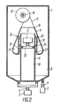
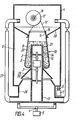
- the periodically acting device for filtering a liquid contains a hermetically sealed housing 1 (FIGS. 1 to 5), which has a check valve 2 with a system 3 for the supply of the filter liquid, and a valve 4 with a system 5 for the discharge of the residue and is connected via a valve 6 to a system 7 for the discharge of the cleaned liquid.
- a hollow cylinder 8, which forms an annular space 9 connected to the residue discharge system 5 with the housing 1, and a flexible filter hose 10 are arranged in the housing 1.
- the filter hose 10 is fastened at one end 11 to a drive drum 12 arranged in the upper part of the housing 1, while its other end 13 is turned inside out and fastened along the circumference to the hollow cylinder 8 to form an annular space 14 around the remaining hose part is, and the filtering liquid is fed to this annular space 14 for filtering.
- the inside 13 of the hose 10 turned to the open end of the hollow cylinder 8 is fixed and lowered into the cylinder space, whereby the enlargement of the annular space 14 under the influence of the residue to be stored therein or its reduction during the upward movement of the hose in the cylinder.
- the cavity of the cylinder 8 is in the lower part with the system 7 for the derivation of the cleaned liquid.
- the end 13 of the hose 10 is on the outer surface of the hollow cylinder 8 in any known manner, e.g. fixed by gluing, using fasteners, etc.
- the end 11 of the hose 10 can be attached directly to the drum 12 or to a rigid ring 16 (FIGS. 2 to 5) to which cables 17 wound on the drum 12 are attached.
- Any known reversing drive is used to rotate the drum 12, which has an electric motor (not shown), a coupling (not shown) for lifting the filter hose 10 and, if necessary, for lowering the hose 10, which coupling is coupled to the shaft of the drum 12.
- the drum 12 is also provided with a means 18 which regulates its torque depending on the set pressure which is exerted on the hose by the filtering liquid and the residue in the annular space 14 of the hose.
- a well-known mechanism for example a ratchet or friction lock, can serve as such means.
- the hose can move during the filtration process in the cavity 19 of the cylinder 8, according to FIG. 1, or over its outer surface, as shown in FIGS. 2 to 5, in the annular space 9 of the housing 1.
- the hose 10 is guided over the outer surface of the cylinder when the filter residue is removed from the annular space 14, the hose end 11 coming to rest in the lower part of the housing, as shown in FIGS. 3 and 5.
- the filter liquid can be supplied via the hollow cylinder 8, as shown in FIGS. 2 to 5.
- the system 3 for supplying the filter liquid is accommodated in the cavity 19 of the cylinder 8, the cavity 19 being divided into sections by partitions 20 (FIGS. 4, 5).
- Through holes 21 are provided in the cylinder 8 for the outflow of the filter liquid.
- a sleeve 22 is arranged in the annular space 14 (FIGS. 2, 3) of the hose coaxially with the cylinder 8. With regard to the cylinder 8 and the end 13 of the hose 10 fastened thereon, the sleeve 22 is arranged with a clearance 23, as a result of which it can move along the cylinder 8 together with the hose 10. To limit the displacement of the sleeve 22 there is an annular stop 24 on the cylinder 8 and a collar 25 on the sleeve 22.
- the liquid can be filtered using any known pourable filler such as sand, gravel, packing, fibers, etc.
- a container 26 (FIGS. 4, 5) connected to the residue discharge system 5 is provided in the lower part of the housing 1.
- the lower part of this container is connected by means of connecting piece 27 to the upper part of the housing via overflow valves.
- the filler (filter medium) is supplied in any known manner to the upper part of the housing 1, where it is passed via a groove 28 into the annular space 14 of the hose 10.
- a flexible sheath 29, for example made of rubber, is provided in the device, which is attached to the hollow cylinder 8 and covers the inflow opening of the container 26. Due to elastic material properties, the sleeve 29 presses against the cylinder under the action of the hose with filler and liquid turning inside out, as a result of which the hose end 11 freely descends and the filler and residue are pushed out into the container 26 can pour. After the hose has moved upward into the starting position, the sleeve 29 restores its shape.
- the device is provided with a means which, after filtering, turns the hose inside out over the outside of the cylinder, whereby the residue is most completely removed from the filter surface and the hose surface is rinsed can.
- An elastic hollow ring 30 serves as such means, which is arranged in the cavity of the cylinder 8 on the fastening section of the hose 10 and is connected to a compressed air system 31 by means of a flexible hose 32. Under the influence of air, the ring 30 increases in size and covers the cylinder 8, as a result of which the hose 10, which has been provisionally raised to the position indicated by the dotted line, is guided over the outer surface of the cylinder, the flexible hose 32 not displacing the hose 10 prevents.
- the device according to the invention is equipped with all the necessary actuating elements and electrical control systems which ensure its automatic operation and which are obvious and well known to those skilled in the art.
- the device according to the invention is operated as follows.
- the hermetic housing 1 With the system 3 (FIG. 1) the hermetic housing 1 is supplied with the filtering liquid through the ring connector 15, which flows into the annular space 14 of the hose 10 and is filtered through the hose 10, while the residue remains in the cavity 14.
- the cleaned liquid flows into the system 7. J e after soiling of the filter surface of the tube to the residue and the Piltrier crampkeit accumulates in the annular space fourteenth
- the means 18 responds, causing the Drum 13 rotates and the contaminated surface portion of the hose descends and migrates to the inner surface of the hollow cylinder 8, and the clean surface of the hose enters the piltration zone, thereby increasing the volume of the annular space 14 of the hose.
- the drive of the drum 12 is switched on, and the hose 10 is wound onto the drum.
- the hose is then lowered by switching the drum drive. Under the action of the residue on its surface, the hose sinks along the outer surface of the cylinder and turns inside out, so that the hose end 11 comes to rest in the lower part of the housing. The residue is found on the open side of the hose 10.
- the residue is washed away from the surface of the hose and fed to the residue drainage system.
- the drum 12 After flushing the hose, the drum 12 begins to rotate in opposite directions and wind up the hose. After the upward movement of the hose 10, air is released from the elastic ring 30 and the hose is lowered into the cavity 19 of the cylinder 8. The filtration cycle is repeated.
- the filter liquid flows from the system 3 through a nozzle 33 arranged in the cylinder 8 through the annular gap 23 between the sleeve 22 and the hose end 13 fastened to the outside of the cylinder 8 into the annular space 14 and is filtered through the hose, the pure hose sections during the filtering process as well as during execution 1 can be supplied.
- the valve 6 has closed and the hose end 11 with the ring 16 has been brought into the lower end position, ie after the hose 10 has turned completely inside out on the outer surface of the cylinder 8 (FIG. 3) the valve 4, and the liquid flows into the system 5 with the residue, the filtering or rinsing liquid jets rinsing the residue away from the surface of the hose as it flows through the annular gap 23.
- valve 4 closes and valve 6 opens.
- the drum 12 begins to rotate in opposite directions and the hose end 11 moves upwards together with the sleeve 22.
- the annular space 14 is formed again and its volume increases.
- the filtration fluid is returned to the cavity 14 and the filtration cycle is repeated.
- the device according to FIGS. 4, 5 functions exactly like the devices according to FIGS. 2, 3. Simultaneously with the lowering of the end 11 and the turning of the hose 10 over the outer surface of the cylinder 8, the sleeve 29 presses against the cylinder 8, and The filler and the residue are poured out of the cavity 14 into the container 26. Through the holes 21 in the lower part of the cylinder 8, the filtering or rinsing liquid flows through the hose and cleans it. The end 11 of the hose 10 is then lifted into the starting position by the rotation of the drum 12, as shown in FIG.
- the residue is passed into the system 5 together with the liquid, and the cleaned filler is fed to the upper part of the housing via the nozzle 27 and poured into the annular space 14 formed via the channel 28.
- the medium to be filtered flows into the cavity 14 through the bores 21 in the upper part of the cylinder, flows through the filler and the hose and is fed to the system 7 through the casing 29.
- the present invention can be used most effectively in the sludge elimination of industrial wastewater, the cleaning of sewage drains by removal of solid inclusions, the circulation and drinking water cleaning by removal of floating particles.
- the invention can be used in the separation of effluents from livestock farms into solid and liquid fractions and in sewer and water basin cleaning by separating digested sludge.
Landscapes
- Chemical & Material Sciences (AREA)
- Chemical Kinetics & Catalysis (AREA)
- Filtration Of Liquid (AREA)
- Nitrogen And Oxygen Or Sulfur-Condensed Heterocyclic Ring Systems (AREA)
- Electrical Discharge Machining, Electrochemical Machining, And Combined Machining (AREA)
- Fittings On The Vehicle Exterior For Carrying Loads, And Devices For Holding Or Mounting Articles (AREA)
Abstract
Priority Applications (1)
| Application Number | Priority Date | Filing Date | Title |
|---|---|---|---|
| AT87900741T ATE65710T1 (de) | 1985-12-24 | 1986-12-17 | Vorrichtung zur filtration einer fluessigkeit. |
Applications Claiming Priority (6)
| Application Number | Priority Date | Filing Date | Title |
|---|---|---|---|
| SU3988612 | 1985-12-24 | ||
| SU3988605 | 1985-12-24 | ||
| SU3988604 | 1985-12-24 | ||
| SU3988605 | 1985-12-24 | ||
| SU853988604A SU1563733A1 (ru) | 1985-12-24 | 1985-12-24 | Устройство дл фильтровани среды |
| SU3988612 | 1985-12-24 |
Publications (3)
| Publication Number | Publication Date |
|---|---|
| EP0252996A1 true EP0252996A1 (fr) | 1988-01-20 |
| EP0252996A4 EP0252996A4 (fr) | 1988-04-26 |
| EP0252996B1 EP0252996B1 (fr) | 1991-07-31 |
Family
ID=27356418
Family Applications (1)
| Application Number | Title | Priority Date | Filing Date |
|---|---|---|---|
| EP87900741A Expired - Lifetime EP0252996B1 (fr) | 1985-12-24 | 1986-12-17 | Dispositif pour le filtrage d'un liquide |
Country Status (8)
| Country | Link |
|---|---|
| US (1) | US4839047A (fr) |
| EP (1) | EP0252996B1 (fr) |
| JP (1) | JPS63501853A (fr) |
| AT (1) | ATE65710T1 (fr) |
| AU (1) | AU591755B2 (fr) |
| CA (1) | CA1294222C (fr) |
| DE (1) | DE3680669D1 (fr) |
| WO (1) | WO1987003822A1 (fr) |
Cited By (2)
| Publication number | Priority date | Publication date | Assignee | Title |
|---|---|---|---|---|
| DE4205550A1 (de) * | 1992-02-24 | 1993-08-26 | Thyssen Industrie | Verfahren zum filtern von brauch- sowie prozesswasser und zum entwaessern von schlamm und filteranlage zur durchfuehrung des verfahrens |
| CN115177996A (zh) * | 2022-09-08 | 2022-10-14 | 无锡维邦工业设备成套技术有限公司 | 一种进料防堵装置及使用该防堵装置的连续灭活设备 |
Families Citing this family (5)
| Publication number | Priority date | Publication date | Assignee | Title |
|---|---|---|---|---|
| US6063294A (en) * | 1996-10-15 | 2000-05-16 | Baker Hughes Incorporated | Uniform area shower for disc filter |
| US6149803A (en) * | 1998-08-28 | 2000-11-21 | Atlantic Contruction Fabrics, Inc. | Storm sewer catch basin filter |
| US20060266216A1 (en) * | 2005-05-24 | 2006-11-30 | Cabot Corporation | High-throughput powder synthesis system |
| US9149743B2 (en) | 2007-10-04 | 2015-10-06 | Michael K. Conwell | Apparatus for dewatering solids-laden liquids |
| US8070960B2 (en) * | 2007-10-04 | 2011-12-06 | Conwell Michael K | Method of dewatering solids laden liquids utilizing a reusable filter element |
Family Cites Families (12)
| Publication number | Priority date | Publication date | Assignee | Title |
|---|---|---|---|---|
| US34499A (en) * | 1862-02-25 | Improvement in coal-sifters | ||
| DE41969C (de) * | A. LÜBCKE in Dresden-Striesen, 1. Strafse Nr. 13 | Neuerung an Trubsäcken für Brauereien | ||
| DE64359C (de) * | 1891-12-03 | 1892-09-09 | G. MÜLLER in Garmisch, im Bayr. Hochlande, Bahnhofstr. 11/4 | Conischer Filtersack ohne Naht für Brauereizwecke |
| GB449025A (en) * | 1934-08-03 | 1936-06-18 | Graham Stedts Gasgenerator Ab | Improved filter for gas producers |
| US3254772A (en) * | 1962-11-13 | 1966-06-07 | Beloit Corp | Filter |
| US3464561A (en) * | 1966-11-15 | 1969-09-02 | American Felt Co | Strainer bag attachment arrangement |
| US3640392A (en) * | 1970-05-19 | 1972-02-08 | Gaf Corp | Pressurized liquid-filtering apparatus |
| US3931015A (en) * | 1974-12-04 | 1976-01-06 | C. B. Kaupp & Sons, Inc. | Filter vessel and filter element assembly |
| SE401895B (sv) * | 1976-05-24 | 1978-06-05 | Ifoe Sanitaer Ab | Sett att avlegsna medelst fibermaterial franskiljbara bestandsdelar fran vetska |
| FR2383130A1 (fr) * | 1977-03-09 | 1978-10-06 | Peyronnet Jean | Decanteur-separateur de boues |
| US4370153A (en) * | 1981-11-12 | 1983-01-25 | Econ Company | Apparatus for cleaning filter bags |
| JP2648176B2 (ja) * | 1988-06-30 | 1997-08-27 | 日清製粉株式会社 | 制癌剤 |
-
1986
- 1986-12-17 DE DE8787900741T patent/DE3680669D1/de not_active Expired - Lifetime
- 1986-12-17 US US07/112,564 patent/US4839047A/en not_active Expired - Fee Related
- 1986-12-17 JP JP87500835A patent/JPS63501853A/ja active Pending
- 1986-12-17 EP EP87900741A patent/EP0252996B1/fr not_active Expired - Lifetime
- 1986-12-17 WO PCT/SU1986/000133 patent/WO1987003822A1/fr not_active Ceased
- 1986-12-17 AT AT87900741T patent/ATE65710T1/de not_active IP Right Cessation
- 1986-12-17 AU AU68954/87A patent/AU591755B2/en not_active Ceased
- 1986-12-23 CA CA000526146A patent/CA1294222C/fr not_active Expired - Lifetime
Cited By (3)
| Publication number | Priority date | Publication date | Assignee | Title |
|---|---|---|---|---|
| DE4205550A1 (de) * | 1992-02-24 | 1993-08-26 | Thyssen Industrie | Verfahren zum filtern von brauch- sowie prozesswasser und zum entwaessern von schlamm und filteranlage zur durchfuehrung des verfahrens |
| CN115177996A (zh) * | 2022-09-08 | 2022-10-14 | 无锡维邦工业设备成套技术有限公司 | 一种进料防堵装置及使用该防堵装置的连续灭活设备 |
| CN115177996B (zh) * | 2022-09-08 | 2022-12-13 | 无锡维邦工业设备成套技术有限公司 | 一种进料防堵装置及使用该防堵装置的连续灭活设备 |
Also Published As
| Publication number | Publication date |
|---|---|
| CA1294222C (fr) | 1992-01-14 |
| WO1987003822A1 (fr) | 1987-07-02 |
| ATE65710T1 (de) | 1991-08-15 |
| JPS63501853A (ja) | 1988-07-28 |
| AU591755B2 (en) | 1989-12-14 |
| EP0252996B1 (fr) | 1991-07-31 |
| EP0252996A4 (fr) | 1988-04-26 |
| US4839047A (en) | 1989-06-13 |
| AU6895487A (en) | 1987-07-15 |
| DE3680669D1 (de) | 1991-09-05 |
Similar Documents
| Publication | Publication Date | Title |
|---|---|---|
| EP1062047B1 (fr) | Separateur cyclone | |
| EP0654294B1 (fr) | Procédé et dispositif de filtration de particules solides de liquides et le rinçage du filtre à contre-courant | |
| DE69221336T2 (de) | Filter mit hin- und hergehender Reinigungsvorrichtung | |
| EP2207609B1 (fr) | Dispositif de filtration | |
| EP1583597B9 (fr) | Dispositif de filtrage | |
| DE3782563T2 (de) | Trommelfiltereinrichtung. | |
| WO2012150010A1 (fr) | Dispositif filtrant | |
| EP0361217B1 (fr) | Filtre à rinçage à contre-courant | |
| DE1611158B2 (de) | Filtereinrichtung | |
| EP0252996A1 (fr) | Dispositif pour le filtrage d'un liquide | |
| EP1137467B1 (fr) | Dispositif d'extraction d'eau claire a partir d'installations a decantation a fonctionnement discontinu | |
| AT409223B (de) | Einrichtung zur reinigung, insbesondere zur filterung, von flüssigkeiten | |
| EP0634199B1 (fr) | Filtre pour eau comportant des éléments contrÔlables de filtration et de lavage à contre-courant | |
| EP1149619A1 (fr) | Dispositif de filtration pour la clarification de liquides contaminés | |
| EP3792408B1 (fr) | Agencement de filtre | |
| DE1536826C3 (de) | Filtervorrichtung | |
| DE1875987U (de) | Dekantier- und/oder siebzentrifuge. | |
| EP0253899A1 (fr) | Dispositif a action periodique pour filtrage d'un milieu liquide | |
| DE19714959B4 (de) | Schlauchfilter zur Flüssigkeitsfiltration | |
| DE3724451C2 (de) | Verfahren zum Ausscheiden filtrierbarer Stoffe aus einer Flüssigkeit und Vorrichtung zur Durchführung desselben | |
| DE102004001200B4 (de) | Vorrichtung zur Sedimentation von Feststoffpartikel enthaltendem Abwasser | |
| DE10240666A1 (de) | Flüssigkeitsfilter, insbesondere für Getriebeöl in Kraftfahrzeugen | |
| WO1996006046A1 (fr) | Installation d'epuration d'eaux usees | |
| DE102004063879A1 (de) | Filtereinrichtung und Verfahren zum Klären von verschmutzten Flüssigkeiten | |
| DE3046388C2 (de) | Spaltfilter für Flüssigkeiten |
Legal Events
| Date | Code | Title | Description |
|---|---|---|---|
| PUAI | Public reference made under article 153(3) epc to a published international application that has entered the european phase |
Free format text: ORIGINAL CODE: 0009012 |
|
| 17P | Request for examination filed |
Effective date: 19870729 |
|
| AK | Designated contracting states |
Kind code of ref document: A1 Designated state(s): AT DE FR GB IT |
|
| A4 | Supplementary search report drawn up and despatched |
Effective date: 19880426 |
|
| 17Q | First examination report despatched |
Effective date: 19890705 |
|
| GRAA | (expected) grant |
Free format text: ORIGINAL CODE: 0009210 |
|
| AK | Designated contracting states |
Kind code of ref document: B1 Designated state(s): AT DE FR GB IT |
|
| REF | Corresponds to: |
Ref document number: 65710 Country of ref document: AT Date of ref document: 19910815 Kind code of ref document: T |
|
| REF | Corresponds to: |
Ref document number: 3680669 Country of ref document: DE Date of ref document: 19910905 |
|
| GBT | Gb: translation of ep patent filed (gb section 77(6)(a)/1977) | ||
| ITF | It: translation for a ep patent filed | ||
| ET | Fr: translation filed | ||
| PGFP | Annual fee paid to national office [announced via postgrant information from national office to epo] |
Ref country code: GB Payment date: 19911209 Year of fee payment: 6 Ref country code: FR Payment date: 19911209 Year of fee payment: 6 |
|
| PGFP | Annual fee paid to national office [announced via postgrant information from national office to epo] |
Ref country code: AT Payment date: 19911210 Year of fee payment: 6 |
|
| PGFP | Annual fee paid to national office [announced via postgrant information from national office to epo] |
Ref country code: DE Payment date: 19920131 Year of fee payment: 6 |
|
| PLBE | No opposition filed within time limit |
Free format text: ORIGINAL CODE: 0009261 |
|
| STAA | Information on the status of an ep patent application or granted ep patent |
Free format text: STATUS: NO OPPOSITION FILED WITHIN TIME LIMIT |
|
| 26N | No opposition filed | ||
| PG25 | Lapsed in a contracting state [announced via postgrant information from national office to epo] |
Ref country code: GB Effective date: 19921217 Ref country code: AT Effective date: 19921217 |
|
| GBPC | Gb: european patent ceased through non-payment of renewal fee |
Effective date: 19921217 |
|
| PG25 | Lapsed in a contracting state [announced via postgrant information from national office to epo] |
Ref country code: FR Effective date: 19930831 |
|
| PG25 | Lapsed in a contracting state [announced via postgrant information from national office to epo] |
Ref country code: DE Effective date: 19930901 |
|
| REG | Reference to a national code |
Ref country code: FR Ref legal event code: ST |
|
| PG25 | Lapsed in a contracting state [announced via postgrant information from national office to epo] |
Ref country code: IT Free format text: LAPSE BECAUSE OF NON-PAYMENT OF DUE FEES;WARNING: LAPSES OF ITALIAN PATENTS WITH EFFECTIVE DATE BEFORE 2007 MAY HAVE OCCURRED AT ANY TIME BEFORE 2007. THE CORRECT EFFECTIVE DATE MAY BE DIFFERENT FROM THE ONE RECORDED. Effective date: 20051217 |