EP0253029A1 - Dispositif de distillation d'eau potable - Google Patents
Dispositif de distillation d'eau potable Download PDFInfo
- Publication number
- EP0253029A1 EP0253029A1 EP86305304A EP86305304A EP0253029A1 EP 0253029 A1 EP0253029 A1 EP 0253029A1 EP 86305304 A EP86305304 A EP 86305304A EP 86305304 A EP86305304 A EP 86305304A EP 0253029 A1 EP0253029 A1 EP 0253029A1
- Authority
- EP
- European Patent Office
- Prior art keywords
- water
- chamber
- evaporation chamber
- distilled
- drinking
- Prior art date
- Legal status (The legal status is an assumption and is not a legal conclusion. Google has not performed a legal analysis and makes no representation as to the accuracy of the status listed.)
- Withdrawn
Links
- 239000003651 drinking water Substances 0.000 title claims abstract description 8
- 235000020188 drinking water Nutrition 0.000 title claims abstract description 8
- XLYOFNOQVPJJNP-UHFFFAOYSA-N water Substances O XLYOFNOQVPJJNP-UHFFFAOYSA-N 0.000 claims abstract description 89
- 238000001704 evaporation Methods 0.000 claims abstract description 29
- 230000008020 evaporation Effects 0.000 claims abstract description 29
- 238000010438 heat treatment Methods 0.000 claims abstract description 17
- 230000035622 drinking Effects 0.000 claims abstract description 6
- 238000001816 cooling Methods 0.000 claims description 5
- 230000008093 supporting effect Effects 0.000 claims description 3
- 239000002918 waste heat Substances 0.000 claims description 2
- 239000012153 distilled water Substances 0.000 description 10
- 238000004519 manufacturing process Methods 0.000 description 5
- 238000011144 upstream manufacturing Methods 0.000 description 3
- 208000014770 Foot disease Diseases 0.000 description 1
- 241000748457 Melampodium Species 0.000 description 1
- 208000008763 Mercury poisoning Diseases 0.000 description 1
- 206010027439 Metal poisoning Diseases 0.000 description 1
- 235000019628 coolness Nutrition 0.000 description 1
- 239000003599 detergent Substances 0.000 description 1
- 238000010586 diagram Methods 0.000 description 1
- 201000010099 disease Diseases 0.000 description 1
- 208000037265 diseases, disorders, signs and symptoms Diseases 0.000 description 1
- 238000004821 distillation Methods 0.000 description 1
- 230000002706 hydrostatic effect Effects 0.000 description 1
- 238000009434 installation Methods 0.000 description 1
- 238000000034 method Methods 0.000 description 1
- 229940127240 opiate Drugs 0.000 description 1
- 230000000630 rising effect Effects 0.000 description 1
- 230000001960 triggered effect Effects 0.000 description 1
- 238000003911 water pollution Methods 0.000 description 1
Images


Classifications
-
- B—PERFORMING OPERATIONS; TRANSPORTING
- B01—PHYSICAL OR CHEMICAL PROCESSES OR APPARATUS IN GENERAL
- B01L—CHEMICAL OR PHYSICAL LABORATORY APPARATUS FOR GENERAL USE
- B01L9/00—Supporting devices; Holding devices
- B01L9/04—Retort stands; Retort clamps
-
- C—CHEMISTRY; METALLURGY
- C02—TREATMENT OF WATER, WASTE WATER, SEWAGE, OR SLUDGE
- C02F—TREATMENT OF WATER, WASTE WATER, SEWAGE, OR SLUDGE
- C02F1/00—Treatment of water, waste water, or sewage
- C02F1/02—Treatment of water, waste water, or sewage by heating
- C02F1/04—Treatment of water, waste water, or sewage by heating by distillation or evaporation
-
- C—CHEMISTRY; METALLURGY
- C02—TREATMENT OF WATER, WASTE WATER, SEWAGE, OR SLUDGE
- C02F—TREATMENT OF WATER, WASTE WATER, SEWAGE, OR SLUDGE
- C02F1/00—Treatment of water, waste water, or sewage
- C02F1/02—Treatment of water, waste water, or sewage by heating
- C02F1/04—Treatment of water, waste water, or sewage by heating by distillation or evaporation
- C02F1/18—Transportable devices to obtain potable water
Definitions
- This invention retates to a distilled drinking water fountain for home use comprising an evaporation chamber to vaporize water resulting from the steam being cooled by the preheating chamber, then a fin-type condenser to condense steam by air, and a storage chamber to collect the condensate for drinking.
- the primary purpose of this invention is to provide a new design of distilled drinking water fountain.
- Another purpose of this invention is to make the distilled water easily accessible. Since the water resource pollution is getting worse,the sale amount of bottled distilled water keeps rising. However, the manufacturers use brush and detergent to clean bottles which does not meet the hygienic standard. Thus, this invention can provide to consumers a device to produce distilled water directly for drinking by themselves and rid the flaws of bottled distilled water.
- This invention employs the method of producing distilled water and has improved distillation efficiency. With its simple design, it can be accepted easily in the family.
- this invention provides a distilled drinking water fountain which includes an equipment frame with a water supply apparatus inside it , an evaporation chamber with a water level control switch and a heating element, a preheating chamber, an air cooling condenser, a water storage chamber with a water level control switch, and a drinking faucet.
- Water is first vaporized at evaporation chamber. Steam is then cooled down at preheating chamber and condensed at the fin shape air cooling condenser. This way, steam can be quickly condensed and collected at the storage chamber for drinking.
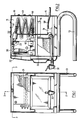
- this invention possesses an equipment frame (10) to form a space (11) which contains an evaporation chamber (20), water storage chamber (30), condenser (40), and water supply pipe (50), etc..
- the lower end of the storage chamber (30) is connected with an effluent pipe (31) which goes directly to the press-button type faucet (32) in front of the equipment frame (10).
- the equipment frame (10) is kept at an appropiate distance above table by a pair of U-shaped supporting tubes (13) at its lower end. This design not only gives one a neat feeling but also provides a space high enough for cup to be placed under the water faucet.
- Water is supplied from the rear side of the water storage room (30), passing through a water supply pipe (50) and a solenoid valve (51), and enters into a preheater (52).
- a preheater (52) There are a variety of ways to set up preheater (52). One of them is shown in Figure 4. The characteristics of this design is that the preheater (52) is installed against the outlet of the evaporation chamber (20). Thus, the preheaded water is injected into the evaporation chamber (20) from the top.
- the bottom of the evaporation chamber (20) contains an adjustable heating element.
- the evaporation chamber (20) also possesses a water level control switch(22). Which utillizes an electrode to control high and low water levels.
- the solenoid valve (51) When the water level control switch (22) is at its high level switch, the solenoid valve (51) would be closed to prevent water overflow from the evaporation chamber (20). If the low level switch is on due to insufficient water level in the evaporation chamber (20), the power supply of the heating element (21) will be cut off heating element (21) from to prevent burning out.
- the condensate flows from the preheating chamber (52) into the condenser (40) which is made of fin-shaped tubings, and then enters the water storage chamber (30).
- the connection head (41) between the condenser (40) and water storage chamber (30) is specially equipped with an exhaust outlet (42) that acts as an safety deviced for this invention.
- the exhaust outlet (42) makes the whole design become open type even though the evaporation chamber (20) and condenser (40) are close type designs. Therefore, the evaporation chamber (20) can switch from the pressure vessel to the open type vessel which reduces the risk of exceeding the atmospheric pressure to minimum.
- ventillation holes (141) and fan (15) installed beneath the condenser (40) which allow air to be blown to the condenser 40 to increase the cooling efficiency.
- the hot air is then exhausted through the ventillation holes (141), which allows this invention to be used as a heater in the cold climates.
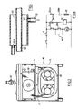
- the structure of the aforesaid preheater (52), as shown in Fig. 4, is a closed cylindrical chamber.
- at least one water inlet (521) and one water outlet (522) are installed on the wall of the preheater (52).
- the water inlet (521) is connected with the upstream of water supplying pipe (50), while the outlet (522) is connected with the downstream pipe between the water supplying pipe (50) and the evaporation chamber (20).
- one hot water tube 43 is welded to connect the evaporation chamber (20) and the condenser (40).
- the hot water tube (43) and the preheater (52) are tightly welded together such that the cold water inputted from the water inlet (521) of the preheater (52) can be heated through the tube wall of the hot water tube (43) (acting as a heat exchanger) inside the preheater (52). This way, cold water entering preheater (52) is heated and high temperature water inside the hot water tube (43) can be initially cooled.
- This design makes the preheater (52) fully efficient.
- the above example is applied under the condition that the water source can (16) be fully supplied and can be connected with water pipe at upstream of the solenoid valve (51).
- the design shown in the Fig. 8 can be used. The characteristics of this design is to install the solenoid valve (51) of the previous example at the location above the central zone of the equipment frame (10) and still allow it to transfer cold water to the preheater (52) through the connection with a downstream pipe.
- the upstream of the solenoid valve (51) is connected to the water outlet (522) located at the bottom of water storage can (16) which is installed on the top of the equipment frame (10).
- Water of the previous example flows through the solenoid valve (52) and enters the evaporation chamber (20) by means of the hydrostatic pressure from the water source. While, in this example, it is the gravitation force produced by the elevation difference between the water storage can (16) and the evaporation chamber (20) that allows water to flow through the solenoid valve (51), due to the gravitational head produced by the elevation difference between the water storage can (16) and the evaporation chamber (20).
- the aforesaid water storage chamber (30) is also equipped with a water level control switch as installed in the evaporation chamber (20). The low level switch actuates the solenoid valve (51) to open for water supply, and the high level switch cut off the power source for the heating element (21) of the evaporator chamber (20) to terminate the steam production.
- the automatic control device of this invention is shown in Fig. 8.
- the integrated circuit is equipped with a fuse F to assure the safety loading.
- the solenoid valve (51) opens automatically for water supply.
- the heating element (21) will automatically start to heat water.
- the solenoid valve (51) will close automatically, while the heating element (21) keeps the heating process still to boil water.
- the steam would be condensed initially through the moisture separator (23), further cooled down at preheater (52) and the condenser (40), and finally the distilled water transported to the water storage chamber (30).
- the heating element (21) in the evaporation chamber (20) will stop heating to prevent more condensed water from entering the water storage chamber (30).
- the heating element (21) has a multi-stage heating control device to give the option for the distilled water production rate when it is necessary.
- the power source switch MC which is used to control the heating element (21) can be made with magnetic switch, relay, or other equivalent components.
- the indicating light is also an optional item.
- the digital water level indicatior can be installed with the water level switch of the water storage chamber (30).
- the design fully utilizes the waste heat, now the distilled water production device no longer belongs only to the factory use, it can become one of the home appliance. This invention is particularly useful for the area where the water pollution is serious the shipping of the distilled water is no longer required.
Landscapes
- Chemical & Material Sciences (AREA)
- Life Sciences & Earth Sciences (AREA)
- Hydrology & Water Resources (AREA)
- Engineering & Computer Science (AREA)
- Environmental & Geological Engineering (AREA)
- Water Supply & Treatment (AREA)
- Organic Chemistry (AREA)
- Health & Medical Sciences (AREA)
- Clinical Laboratory Science (AREA)
- Chemical Kinetics & Catalysis (AREA)
- Heat Treatment Of Water, Waste Water Or Sewage (AREA)
Priority Applications (1)
| Application Number | Priority Date | Filing Date | Title |
|---|---|---|---|
| EP86305304A EP0253029A1 (fr) | 1986-07-10 | 1986-07-10 | Dispositif de distillation d'eau potable |
Applications Claiming Priority (1)
| Application Number | Priority Date | Filing Date | Title |
|---|---|---|---|
| EP86305304A EP0253029A1 (fr) | 1986-07-10 | 1986-07-10 | Dispositif de distillation d'eau potable |
Publications (1)
| Publication Number | Publication Date |
|---|---|
| EP0253029A1 true EP0253029A1 (fr) | 1988-01-20 |
Family
ID=8196062
Family Applications (1)
| Application Number | Title | Priority Date | Filing Date |
|---|---|---|---|
| EP86305304A Withdrawn EP0253029A1 (fr) | 1986-07-10 | 1986-07-10 | Dispositif de distillation d'eau potable |
Country Status (1)
| Country | Link |
|---|---|
| EP (1) | EP0253029A1 (fr) |
Cited By (10)
| Publication number | Priority date | Publication date | Assignee | Title |
|---|---|---|---|---|
| EP0499356A1 (fr) * | 1991-01-18 | 1992-08-19 | Emerson Electric Company | Dispositif de distillation d'eau à structure de faible épaisseur |
| US5250696A (en) * | 1990-11-01 | 1993-10-05 | Sterling Winthrop Inc. | 2-saccharinylmethyl aryl carboxylate |
| US5376653A (en) * | 1991-12-30 | 1994-12-27 | Sterling Winthrop Inc. | 2-saccharinylmethyl heterocyclic carboxylates useful as proteolytic enzyme inhibitors |
| US5385923A (en) * | 1991-12-30 | 1995-01-31 | Sterling Winthrop Inc. | 2-saccharinylmethyl aryl and aryloxy acetates useful as proteolytic enzyme inhibitors |
| US5512589A (en) * | 1990-11-01 | 1996-04-30 | Sterling Winthrop Inc. | 2-saccharinylmethyl aryl carboxylates useful as proteolytic enzyme inhibitors and compositions and method of use thereof |
| RU2117633C1 (ru) * | 1997-05-27 | 1998-08-20 | Закрытое акционерное общество Инвестиционная компания "ФАУНД" | Дистиллятор |
| WO2000058223A1 (fr) * | 1999-03-25 | 2000-10-05 | Koninklijke Philips Electronics N.V. | Appareil de traitement des eaux |
| WO2011134349A1 (fr) * | 2010-04-28 | 2011-11-03 | Wang Longming | Dispositif de distribution d'eau potable à distillation et unité de chauffage de celui-ci à économie d'énergie |
| WO2016044535A1 (fr) * | 2014-09-17 | 2016-03-24 | Deka Products Limited Partnership | Appareil, procede et systeme de distillation de vapeur d'eau |
| CN112755571A (zh) * | 2020-12-31 | 2021-05-07 | 湖南省湘澧盐化有限责任公司 | 一种蒸馏器无人值守自动控制系统 |
Citations (6)
| Publication number | Priority date | Publication date | Assignee | Title |
|---|---|---|---|---|
| DE117271C (fr) * | ||||
| DE349586C (de) * | 1922-03-04 | Bruno Hilliger Dr | Verfahren zur Erzeugung destillierten Wassers | |
| US3055810A (en) * | 1958-03-03 | 1962-09-25 | Ross E Skow | Method and apparatus for purifying water |
| US3256159A (en) * | 1963-07-01 | 1966-06-14 | Salzer Alexander | Water purification apparatus |
| US4247369A (en) * | 1979-06-11 | 1981-01-27 | Bean Roy E | Apparatus for continuous distillation |
| US4415075A (en) * | 1981-09-16 | 1983-11-15 | General Molding, Inc. | Wall mounted light weight automatic water distiller |
-
1986
- 1986-07-10 EP EP86305304A patent/EP0253029A1/fr not_active Withdrawn
Patent Citations (6)
| Publication number | Priority date | Publication date | Assignee | Title |
|---|---|---|---|---|
| DE117271C (fr) * | ||||
| DE349586C (de) * | 1922-03-04 | Bruno Hilliger Dr | Verfahren zur Erzeugung destillierten Wassers | |
| US3055810A (en) * | 1958-03-03 | 1962-09-25 | Ross E Skow | Method and apparatus for purifying water |
| US3256159A (en) * | 1963-07-01 | 1966-06-14 | Salzer Alexander | Water purification apparatus |
| US4247369A (en) * | 1979-06-11 | 1981-01-27 | Bean Roy E | Apparatus for continuous distillation |
| US4415075A (en) * | 1981-09-16 | 1983-11-15 | General Molding, Inc. | Wall mounted light weight automatic water distiller |
Cited By (12)
| Publication number | Priority date | Publication date | Assignee | Title |
|---|---|---|---|---|
| US5250696A (en) * | 1990-11-01 | 1993-10-05 | Sterling Winthrop Inc. | 2-saccharinylmethyl aryl carboxylate |
| US5512589A (en) * | 1990-11-01 | 1996-04-30 | Sterling Winthrop Inc. | 2-saccharinylmethyl aryl carboxylates useful as proteolytic enzyme inhibitors and compositions and method of use thereof |
| EP0499356A1 (fr) * | 1991-01-18 | 1992-08-19 | Emerson Electric Company | Dispositif de distillation d'eau à structure de faible épaisseur |
| AU648633B2 (en) * | 1991-01-18 | 1994-04-28 | Emerson Electric Co. | A low profile water distiller |
| US5376653A (en) * | 1991-12-30 | 1994-12-27 | Sterling Winthrop Inc. | 2-saccharinylmethyl heterocyclic carboxylates useful as proteolytic enzyme inhibitors |
| US5385923A (en) * | 1991-12-30 | 1995-01-31 | Sterling Winthrop Inc. | 2-saccharinylmethyl aryl and aryloxy acetates useful as proteolytic enzyme inhibitors |
| RU2117633C1 (ru) * | 1997-05-27 | 1998-08-20 | Закрытое акционерное общество Инвестиционная компания "ФАУНД" | Дистиллятор |
| WO2000058223A1 (fr) * | 1999-03-25 | 2000-10-05 | Koninklijke Philips Electronics N.V. | Appareil de traitement des eaux |
| WO2011134349A1 (fr) * | 2010-04-28 | 2011-11-03 | Wang Longming | Dispositif de distribution d'eau potable à distillation et unité de chauffage de celui-ci à économie d'énergie |
| DE112011101458B4 (de) * | 2010-04-28 | 2017-09-14 | Shanghai Ariba Electric Co., Ltd | Trinkwasserspender mit Destillationsvorrichtung |
| WO2016044535A1 (fr) * | 2014-09-17 | 2016-03-24 | Deka Products Limited Partnership | Appareil, procede et systeme de distillation de vapeur d'eau |
| CN112755571A (zh) * | 2020-12-31 | 2021-05-07 | 湖南省湘澧盐化有限责任公司 | 一种蒸馏器无人值守自动控制系统 |
Similar Documents
| Publication | Publication Date | Title |
|---|---|---|
| US5286351A (en) | Water distilling method | |
| US6996334B1 (en) | Boilerless steamer apparatus and method to reduce water useage | |
| US6113744A (en) | Water distillation apparatus | |
| US5094721A (en) | Multiple-effect evaporation system and process | |
| US3055810A (en) | Method and apparatus for purifying water | |
| IE48026B1 (en) | Hot water system | |
| NO851210L (no) | Oppvarmingsanordning | |
| NO850165L (no) | Solenergidrevet system for frembringelse av kulde | |
| US4103509A (en) | Water heater-dehumidifier combination heat pump | |
| US4915793A (en) | Water treatment apparatus | |
| US4513585A (en) | Hot water system using a compressor | |
| JPH11500521A (ja) | 間欠的に動作する冷却ユニットを備えた冷凍装置 | |
| US4607688A (en) | Autogenous solar water heater | |
| FR2821924B1 (fr) | Echangeur de chaleur a condensation, notamment pour chaudiere | |
| CN1322283C (zh) | 电热水器的加热装置及加热方法 | |
| US2203207A (en) | Refrigerating apparatus | |
| JP3007868U (ja) | 蒸留水製造機 | |
| US2244126A (en) | Humidifier | |
| US5676800A (en) | Distilling apparatus | |
| JPS5917252Y2 (ja) | 揚げ物製造装置 | |
| KR200304015Y1 (ko) | 순간 냉온수기 | |
| US20070051613A1 (en) | Tap water purifier | |
| KR970005848Y1 (ko) | 간이증류수 제조기 | |
| CN220870906U (zh) | 一种壁挂炉外置节能系统及壁挂炉 | |
| JPS6340118B2 (fr) |
Legal Events
| Date | Code | Title | Description |
|---|---|---|---|
| PUAI | Public reference made under article 153(3) epc to a published international application that has entered the european phase |
Free format text: ORIGINAL CODE: 0009012 |
|
| AK | Designated contracting states |
Kind code of ref document: A1 Designated state(s): DE FR GB IT |
|
| STAA | Information on the status of an ep patent application or granted ep patent |
Free format text: STATUS: THE APPLICATION IS DEEMED TO BE WITHDRAWN |
|
| 18D | Application deemed to be withdrawn |
Effective date: 19880721 |