EP0253050A1 - Elément électrique chauffant avec spires en forme de méandres - Google Patents
Elément électrique chauffant avec spires en forme de méandres Download PDFInfo
- Publication number
- EP0253050A1 EP0253050A1 EP87100773A EP87100773A EP0253050A1 EP 0253050 A1 EP0253050 A1 EP 0253050A1 EP 87100773 A EP87100773 A EP 87100773A EP 87100773 A EP87100773 A EP 87100773A EP 0253050 A1 EP0253050 A1 EP 0253050A1
- Authority
- EP
- European Patent Office
- Prior art keywords
- radiator according
- insulating
- temperature switch
- rail
- webs
- Prior art date
- Legal status (The legal status is an assumption and is not a legal conclusion. Google has not performed a legal analysis and makes no representation as to the accuracy of the status listed.)
- Granted
Links
Images


Classifications
-
- H—ELECTRICITY
- H05—ELECTRIC TECHNIQUES NOT OTHERWISE PROVIDED FOR
- H05B—ELECTRIC HEATING; ELECTRIC LIGHT SOURCES NOT OTHERWISE PROVIDED FOR; CIRCUIT ARRANGEMENTS FOR ELECTRIC LIGHT SOURCES, IN GENERAL
- H05B3/00—Ohmic-resistance heating
- H05B3/10—Heating elements characterised by the composition or nature of the materials or by the arrangement of the conductor
- H05B3/16—Heating elements characterised by the composition or nature of the materials or by the arrangement of the conductor the conductor being mounted on an insulating base
-
- H—ELECTRICITY
- H05—ELECTRIC TECHNIQUES NOT OTHERWISE PROVIDED FOR
- H05B—ELECTRIC HEATING; ELECTRIC LIGHT SOURCES NOT OTHERWISE PROVIDED FOR; CIRCUIT ARRANGEMENTS FOR ELECTRIC LIGHT SOURCES, IN GENERAL
- H05B3/00—Ohmic-resistance heating
- H05B3/20—Heating elements having extended surface area substantially in a two-dimensional [2D] plane, e.g. plate-heater
- H05B3/22—Heating elements having extended surface area substantially in a two-dimensional [2D] plane, e.g. plate-heater non-flexible
- H05B3/26—Heating elements having extended surface area substantially in a two-dimensional [2D] plane, e.g. plate-heater non-flexible heating conductor mounted on insulating base
-
- H—ELECTRICITY
- H05—ELECTRIC TECHNIQUES NOT OTHERWISE PROVIDED FOR
- H05B—ELECTRIC HEATING; ELECTRIC LIGHT SOURCES NOT OTHERWISE PROVIDED FOR; CIRCUIT ARRANGEMENTS FOR ELECTRIC LIGHT SOURCES, IN GENERAL
- H05B2203/00—Aspects relating to Ohmic resistive heating covered by group H05B3/00
- H05B2203/002—Heaters using a particular layout for the resistive material or resistive elements
- H05B2203/003—Heaters using a particular layout for the resistive material or resistive elements using serpentine layout
-
- H—ELECTRICITY
- H05—ELECTRIC TECHNIQUES NOT OTHERWISE PROVIDED FOR
- H05B—ELECTRIC HEATING; ELECTRIC LIGHT SOURCES NOT OTHERWISE PROVIDED FOR; CIRCUIT ARRANGEMENTS FOR ELECTRIC LIGHT SOURCES, IN GENERAL
- H05B2203/00—Aspects relating to Ohmic resistive heating covered by group H05B3/00
- H05B2203/014—Heaters using resistive wires or cables not provided for in H05B3/54
-
- H—ELECTRICITY
- H05—ELECTRIC TECHNIQUES NOT OTHERWISE PROVIDED FOR
- H05B—ELECTRIC HEATING; ELECTRIC LIGHT SOURCES NOT OTHERWISE PROVIDED FOR; CIRCUIT ARRANGEMENTS FOR ELECTRIC LIGHT SOURCES, IN GENERAL
- H05B2203/00—Aspects relating to Ohmic resistive heating covered by group H05B3/00
- H05B2203/016—Heaters using particular connecting means
Definitions
- the invention relates to an electric radiator with a heating conductor in the form of meandering windings, the individual windings being held in at least one insulating material plate in openings separated by webs.
- Such electric radiators are known for example from DE-PS 11 85 743, DE-PS 14 40 381, DE-PS 14 40 404 and DE-PS 12 74 760.
- U-shaped sheet metal strips as stiffening rails are known for example from DE-PS 12 58 523 or DE-OS 31 41 828; the strips there, however, at best ensure stiffening in one direction of extension and cannot readily be used as a return conductor.
- the use of a metal strip as a return conductor, to put both connection contacts of a radiator for bread toast on one side is known from DE-PS 16 15 253.
- the invention has for its object to provide a generic radiator, in particular with a large length and a small width in a technically simple and advantageous manner with greater stability.
- the above object is achieved in an electric radiator with a heating conductor in the form of meandering windings, the individual windings being held in at least one insulating material plate in openings separated by webs, in that an integral holding rail is provided which extends over the entire width of the insulating material plates and essentially extends their length and has bent tabs on both sides of the insulating material plates on both sides of the same, which overlap the insulating material plates.
- an integral holding rail is provided which extends over the entire width of the insulating material plates and essentially extends their length and has bent tabs on both sides of the insulating material plates on both sides of the same, which overlap the insulating material plates.
- connection contacts are provided on one end face for the connection of electrical connections and the heating conductors are electrically connected to the rail on the other end face
- the rail has openings and webs on the side facing away from the tabs having.
- the invention creates a possibly narrow and elongated, highly stable radiator in a simple manner in terms of production technology. If the holding notes are made of metallic material and are used as return conductors, their connection contact can be loosened to them or, in an extremely preferred embodiment, can be formed in one piece with the holding rail.
- the electrical connection of the heating conductor on the end face opposite the connection end face is preferably carried out via an eyelet, so that a reliable mechanical and electrical contact is established here.
- the invention therefore provides in an extremely preferred embodiment that a temperature switch is slidably attached to the holding rail, wherein in particular the holding rail is encompassed by tabs of a holder for a temperature switch.
- the temperature switch can be secured to it against falling or removing, but can be mounted displaceably along the rail or the rails. This makes it possible to manufacture the complete radiator with the associated temperature switch and to store it with a processor who will then, depending on the installation conditions moves the temperature switch along the rail to a desired location, where the temperature switch is either held non-positively or cannot be fixed releasably, for example by riveting or soldering to the rail.
- the temperature switch can be fixed to the holding rail by means of the webs.
- the rail can also be used as a conductor for the current conducted via the temperature switch, so that the rail is made into an electrical connection via the holder for the temperature switch to make a contact.
- the other contact of the switch must be insulated from the holder of the switch and be provided with a separate connection element for connecting a cable.
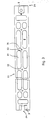
- the electric heater 1 has a heating conductor 2 ⁇ with initially one or more rows of meandering turns 2 made of electrical resistance wire.
- the legs of a turn 2 are longer than their distance.
- the turns 2 are fixed to a first insulating plate 3 in the following way:
- the insulating plate 3 has openings 4 which are separated from one another by webs 6.
- One end 7 of a turn passes through an opening 4, is then guided around the web 6 and emerges again through an adjacent opening 4.
- the assembly of the insulating plate 3 and the heating conductor 2 ⁇ with the turns 2 can be done in that the insulating plate 3 with their openings on the ends 7 facing away from the ends 8 of the turns 2 are performed.
- Another insulating plate 9 is placed on the side of the insulating plate 3 facing away from the heating conductor 2 ist.
- the radiator described so far is stiffened and in particular the two insulating plates 3, 9 are held together by a stiffening rail 11 which extends on the side of the insulating plates 3, 9 facing away from the heating conductor 2 with a main part 12 over the entire width of the insulating plates 3, 9 and has at its longitudinal edges around the longitudinal edges 13, 14 of the insulating plates 3, 9 except for the top 16 of the insulating plate 3 tabs 17 bent by 180 degrees.
- the plates 3, 9 are firmly clamped against one another and the entire radiator 1 is stabilized.
- connecting parts 24 with contact tabs 22, 23 are first arranged, which are in electrical connection with the heating conductor 2 ⁇ and serve to connect the heating conductor 2 ⁇ as electrical connections.
- the rows of meanders are contacted as follows: in the end region of the upper insulating plate 3, an insulating web 19 delimited by two slots 18 is formed in alignment with the rows of meanders. On this sits a vertical section U-shaped connecting part 24 with a bottom web 29, which has a side in the slots 18 and the insulating web 19 encompassing tabs 36.
- a connecting part 24 On the connecting part 24, on the one hand, one of the contact tabs 22 and 23 for connecting connecting lines and, on the other hand, a crimping part 37 for connection to the end 38 of a row of turns is formed.
- the end 38 of the row of turns is a piece through a last opening 4 of the insulating plate 3 and between legs 39 of the crimping part 37, which firmly grip it after being squeezed together.
- the rail 11 On the first end face 21 of the radiator 1, the rail 11 is also provided with a connection contact 28 which is riveted to it, for example.
- the heating conductor 2 ⁇ In the area of the end face 21 facing away from the end face 21, the heating conductor 2 ⁇ is electrically connected to the rail 11, for example via a rivet or in principle in the manner described above for the connecting parts 24 with a connecting part 27, which with a crimping part 67 is a bent-up tab 68 Rail 11 grips tightly.
- the rail 11 serves as a return conductor, so that in the illustrated embodiment, depending on the circuit with the contact tabs 22, 23, 28 connected connecting line to a power supply, the two rows of the heating conductor 2 ⁇ can be connected either individually or together. Also, if necessary, a row of the heating conductor 2 ⁇ via the middle connection contact 28 Serve for a motor to be connected, for example a fan.
- a contact created on the end face 26 facing away from the first end face 21 by the heating conductor 22 to the rail 21 can enable the power supply to be connected on one end to the first end face 21 via the possibilities explained above.
- the rail 11 has openings 31 and webs 32 on the side facing away from the heating conductor 2 ⁇ .
- This configuration improves, in particular, the compensation of the different thermal expansion behavior of the insulating plates 3, 9 and the rail 11.
- this arrangement can serve, with suitable installation conditions, to dispense with the second insulating plate 9 or to hold the heating conductor, if necessary 2 ⁇ to be provided approximately in the middle of the winding height.
- the webs 32 of the holding rail 11 have central widenings 33 with a through hole 34.
- a corresponding projection of a holder 41 for a temperature switch 42 which can be moved along the rail 11 can snap into these holes 34 (FIG. 4).
- the holder 41 of a temperature switch 42 can also be loosened or dotted on the widened webs 32 with the openings 34.
- the insulating material plates 3, 9 with the holes 34 aligned openings 69 ( Figure 1) with a larger radius, so that the loosening can easily be done on finished radiators.
- a corresponding holder 41 for a temperature switch 42 can be seen in particular from FIGS. 4 to 6.
- the bracket 41 first has the width of the rail 11 bridging bow-like web 43, at the ends of which the tabs 17 of the holding rail 11 are formed around tabs 44, by means of which the holder 41 is held on the rail 11 and is displaceable along the latter.
- a bead 46 is formed centrally in the web 43 and bears against the tabs 44 on the underside of the holding rail 11 or in the area of the openings 32 of the lower insulating plate 14 as an abutment. With the bead 46, the holder 41 can be fixed after setting in the desired position on the holding rail 11, for example by spot welding or the like.
- a shoulder 47 On one side extends from the web 43, essentially in alignment with it, a shoulder 47, from which in turn a flange 48 protrudes upward, the end 49 of which is bent laterally. At this bent end 49, the temperature switch 42 is fastened with a contact 51, as if it had been loosened.
- an insulating bridge 52 On the web 47, an insulating bridge 52 is insulated from the web 47 and an angular part 53 is fastened with a flange 54.
- a projection 56 of the insulating part 52 protrudes between the shoulder 47 and the flange 54, by means of which the parts 47, 54 connected to the insulating part 52, for example by eyelets, are held in a rotationally secure manner.
- the other end 58 of the temperature switch 42 which is held securely in this way, is fastened to a flange 57 which is bent away from the angle part 53 against the direction of the extension 54 but also the extension 49 of the part 48.
- 61 is an insulating support part of the temperature switch, with 62 a bearing for a bimetallic disk 63, with 64 the movable contact switched by the bimetallic disk 63 and with 66 the stationary counter contact of the temperature switch 42 cut out and bent out of the contact tab 58.
- a plurality of temperature switches on the holding rail 11 can also be behind by the configuration according to the invention are arranged and if necessary fixed so that local overheating, which would not lead to a safety shutdown in a device with only one monitor, if they occur away from it, are reliably taken into account.
- Several temperature switches in the form of controllers can also be provided. Part of the temperature switch can also be a controller and another part can be a watchdog.
Landscapes
- Resistance Heating (AREA)
- Air-Conditioning For Vehicles (AREA)
Applications Claiming Priority (2)
| Application Number | Priority Date | Filing Date | Title |
|---|---|---|---|
| DE19863622478 DE3622478A1 (de) | 1986-07-04 | 1986-07-04 | Elektrischer heizkoerper mit maeanderfoermigen windungen |
| DE3622478 | 1986-07-04 |
Publications (2)
| Publication Number | Publication Date |
|---|---|
| EP0253050A1 true EP0253050A1 (fr) | 1988-01-20 |
| EP0253050B1 EP0253050B1 (fr) | 1991-12-11 |
Family
ID=6304382
Family Applications (1)
| Application Number | Title | Priority Date | Filing Date |
|---|---|---|---|
| EP87100773A Expired - Lifetime EP0253050B1 (fr) | 1986-07-04 | 1987-01-21 | Elément électrique chauffant avec spires en forme de méandres |
Country Status (3)
| Country | Link |
|---|---|
| US (1) | US4845345A (fr) |
| EP (1) | EP0253050B1 (fr) |
| DE (2) | DE3622478A1 (fr) |
Families Citing this family (4)
| Publication number | Priority date | Publication date | Assignee | Title |
|---|---|---|---|---|
| CA2594248A1 (fr) * | 2007-07-20 | 2009-01-20 | Mabe Canada Inc. | Bloc chauffant |
| RU2435335C1 (ru) * | 2008-01-30 | 2011-11-27 | Косиро ТАГУТИ | Отопитель для транспортного средства и способ его производства |
| CA2763532C (fr) * | 2011-01-18 | 2015-03-31 | Tutco, Llc | Chaufferette a resistance electrique a deux niveau et methode d'utilisation connexe |
| US9386634B2 (en) * | 2011-04-15 | 2016-07-05 | Tutco, Inc. | Electrical resistance heater assembly and method of use |
Citations (5)
| Publication number | Priority date | Publication date | Assignee | Title |
|---|---|---|---|---|
| CH40144A (de) * | 1907-07-15 | 1908-06-16 | Therma Ag | Elektrisches Widerstands- und Heizelement |
| DE1274760B (de) * | 1962-10-24 | 1968-08-08 | Eichenauer Fa Fritz | Halterung fuer zickzackfoermig gebogene Heizsysteme von hochbelastbaren Elektroheizkoerpern |
| US3808573A (en) * | 1973-01-16 | 1974-04-30 | Emerson Electric Co | Electric heater assemblies |
| AT329702B (de) * | 1974-05-14 | 1976-05-25 | Koegler Adalbert | Plattenartiger flachenheizkorper |
| DE3141828A1 (de) * | 1980-10-21 | 1982-07-01 | R.I.C.A. Resistenze Industriali Corazzate ed Affini S.p.A., San Giacomo di Veglia, Treviso | Elektrischer heizwiderstand |
Family Cites Families (8)
| Publication number | Priority date | Publication date | Assignee | Title |
|---|---|---|---|---|
| DE7503313U (de) * | 1975-06-05 | Siemens Ag | Elektrischer Rohrheizkörper | |
| CH125907A (fr) * | 1927-02-26 | 1928-06-01 | Pitton & Collombat | Corps de chauffe électrique. |
| DE1185743B (de) * | 1960-03-05 | 1965-01-21 | Eichenauer Fa Fritz | Hochbelastbarer Elektroheizkoerper |
| US3069522A (en) * | 1960-10-07 | 1962-12-18 | Frederick W Jamison | Heater element for embedment in a mastic slab |
| DE1440404B2 (de) * | 1962-10-24 | 1969-10-09 | Fa. Fritz Eichenauer, 6747 Kandel | Hochbelastbarer Elektroheizkörper |
| DE1258523B (de) * | 1964-06-06 | 1968-01-11 | Eichenauer Fa Fritz | Heizkoerper fuer Brotroester |
| DE2849258A1 (de) * | 1978-11-14 | 1980-05-29 | Eichenauer Fa Fritz | Elektrischer heizkoerper fuer fluide medien |
| JPS5628489A (en) * | 1979-08-14 | 1981-03-20 | Ube Industries | Heating material and method of producing same |
-
1986
- 1986-07-04 DE DE19863622478 patent/DE3622478A1/de not_active Withdrawn
-
1987
- 1987-01-21 DE DE8787100773T patent/DE3775126D1/de not_active Expired - Lifetime
- 1987-01-21 EP EP87100773A patent/EP0253050B1/fr not_active Expired - Lifetime
- 1987-07-06 US US07/070,238 patent/US4845345A/en not_active Expired - Fee Related
Patent Citations (5)
| Publication number | Priority date | Publication date | Assignee | Title |
|---|---|---|---|---|
| CH40144A (de) * | 1907-07-15 | 1908-06-16 | Therma Ag | Elektrisches Widerstands- und Heizelement |
| DE1274760B (de) * | 1962-10-24 | 1968-08-08 | Eichenauer Fa Fritz | Halterung fuer zickzackfoermig gebogene Heizsysteme von hochbelastbaren Elektroheizkoerpern |
| US3808573A (en) * | 1973-01-16 | 1974-04-30 | Emerson Electric Co | Electric heater assemblies |
| AT329702B (de) * | 1974-05-14 | 1976-05-25 | Koegler Adalbert | Plattenartiger flachenheizkorper |
| DE3141828A1 (de) * | 1980-10-21 | 1982-07-01 | R.I.C.A. Resistenze Industriali Corazzate ed Affini S.p.A., San Giacomo di Veglia, Treviso | Elektrischer heizwiderstand |
Also Published As
| Publication number | Publication date |
|---|---|
| DE3622478A1 (de) | 1988-01-07 |
| EP0253050B1 (fr) | 1991-12-11 |
| US4845345A (en) | 1989-07-04 |
| DE3775126D1 (de) | 1992-01-23 |
Similar Documents
| Publication | Publication Date | Title |
|---|---|---|
| DE2620004C3 (de) | Elektrokochplatte mit einem Temperaturbegrenzer | |
| DE69524702T2 (de) | Elektrischer Verbindungskasten | |
| DE2509158C3 (de) | Elektrische Klemme | |
| EP0333906A1 (fr) | Résistance chauffante à coefficient de température positif | |
| DE3104827C2 (fr) | ||
| EP0253050A1 (fr) | Elément électrique chauffant avec spires en forme de méandres | |
| EP0223168A1 (fr) | Plaque de cuisson électrique et dispositif pour sa connexion | |
| DE3102640C2 (fr) | ||
| DE2709413C3 (de) | Heizkörper für elektrische Geräte mit einem Gebläse | |
| DE2414812A1 (de) | Ausdehnungsdose fuer temperaturempfindliche systeme | |
| DE3540816A1 (de) | Elektrokochplatte sowie vorrichtung fuer deren anschluss | |
| DE69907264T2 (de) | Elektrisches koch- und toastgerät sowie zugehörige elektrische elemente | |
| DE4409123A1 (de) | Gerät zum Erwärmen von Flüssigkeiten | |
| DE1127007B (de) | Elektrisch beheizte Masse-Schnellkochplatte | |
| DE3418667C2 (fr) | ||
| EP0304906A2 (fr) | Boîtier de connexion pour plaques électriques de cuisson | |
| EP0289707B1 (fr) | Elément chauffant électrique avec prise | |
| EP0243647B1 (fr) | Disjoncteur avec déclenchement thermique | |
| DE3041597A1 (de) | Heizeinrichtung fuer grosse beheizungsflaeche | |
| DE1640197B2 (de) | Bimetallschalter | |
| DE69705397T2 (de) | Verbessertes elektrisches heizgerät für flussigkeiten und steuerung dafür | |
| DE19613328C1 (de) | Durchlauferhitzer für ein wassererhitzendes Haushaltsgerät | |
| DE3227623C1 (de) | Anschlußeinrichtung für einen, vorzugsweise perlenisolierten Strahlungsheizkörper, insbesondere für eine Backofenheizung | |
| DE2604764B2 (de) | Elektrische anschlussvorrichtung fuer eine gekapselte kaeltemaschine | |
| DE202004006125U1 (de) | Verteilerleiste |
Legal Events
| Date | Code | Title | Description |
|---|---|---|---|
| PUAI | Public reference made under article 153(3) epc to a published international application that has entered the european phase |
Free format text: ORIGINAL CODE: 0009012 |
|
| AK | Designated contracting states |
Kind code of ref document: A1 Designated state(s): CH DE ES FR GB IT LI SE |
|
| 17P | Request for examination filed |
Effective date: 19880627 |
|
| 17Q | First examination report despatched |
Effective date: 19900419 |
|
| GRAA | (expected) grant |
Free format text: ORIGINAL CODE: 0009210 |
|
| AK | Designated contracting states |
Kind code of ref document: B1 Designated state(s): CH DE ES FR GB IT LI SE |
|
| PG25 | Lapsed in a contracting state [announced via postgrant information from national office to epo] |
Ref country code: SE Effective date: 19911211 |
|
| REF | Corresponds to: |
Ref document number: 3775126 Country of ref document: DE Date of ref document: 19920123 |
|
| PG25 | Lapsed in a contracting state [announced via postgrant information from national office to epo] |
Ref country code: LI Effective date: 19920131 Ref country code: CH Effective date: 19920131 |
|
| ET | Fr: translation filed | ||
| ITF | It: translation for a ep patent filed | ||
| PG25 | Lapsed in a contracting state [announced via postgrant information from national office to epo] |
Ref country code: ES Free format text: LAPSE BECAUSE OF FAILURE TO SUBMIT A TRANSLATION OF THE DESCRIPTION OR TO PAY THE FEE WITHIN THE PRESCRIBED TIME-LIMIT Effective date: 19920322 |
|
| GBT | Gb: translation of ep patent filed (gb section 77(6)(a)/1977) | ||
| REG | Reference to a national code |
Ref country code: CH Ref legal event code: PL |
|
| PLBE | No opposition filed within time limit |
Free format text: ORIGINAL CODE: 0009261 |
|
| STAA | Information on the status of an ep patent application or granted ep patent |
Free format text: STATUS: NO OPPOSITION FILED WITHIN TIME LIMIT |
|
| 26N | No opposition filed | ||
| PGFP | Annual fee paid to national office [announced via postgrant information from national office to epo] |
Ref country code: GB Payment date: 19950112 Year of fee payment: 9 |
|
| PG25 | Lapsed in a contracting state [announced via postgrant information from national office to epo] |
Ref country code: GB Effective date: 19960121 |
|
| GBPC | Gb: european patent ceased through non-payment of renewal fee |
Effective date: 19960121 |
|
| PGFP | Annual fee paid to national office [announced via postgrant information from national office to epo] |
Ref country code: DE Payment date: 19991230 Year of fee payment: 14 |
|
| PGFP | Annual fee paid to national office [announced via postgrant information from national office to epo] |
Ref country code: FR Payment date: 20000118 Year of fee payment: 14 |
|
| PG25 | Lapsed in a contracting state [announced via postgrant information from national office to epo] |
Ref country code: FR Free format text: LAPSE BECAUSE OF NON-PAYMENT OF DUE FEES Effective date: 20010928 |
|
| PG25 | Lapsed in a contracting state [announced via postgrant information from national office to epo] |
Ref country code: DE Free format text: LAPSE BECAUSE OF NON-PAYMENT OF DUE FEES Effective date: 20011101 |
|
| REG | Reference to a national code |
Ref country code: FR Ref legal event code: ST |
|
| PG25 | Lapsed in a contracting state [announced via postgrant information from national office to epo] |
Ref country code: IT Free format text: LAPSE BECAUSE OF NON-PAYMENT OF DUE FEES;WARNING: LAPSES OF ITALIAN PATENTS WITH EFFECTIVE DATE BEFORE 2007 MAY HAVE OCCURRED AT ANY TIME BEFORE 2007. THE CORRECT EFFECTIVE DATE MAY BE DIFFERENT FROM THE ONE RECORDED. Effective date: 20050121 |