EP0253105B1 - Integrierte Schaltung mit verbesserter Schutzvorrichtung - Google Patents
Integrierte Schaltung mit verbesserter Schutzvorrichtung Download PDFInfo
- Publication number
- EP0253105B1 EP0253105B1 EP87107503A EP87107503A EP0253105B1 EP 0253105 B1 EP0253105 B1 EP 0253105B1 EP 87107503 A EP87107503 A EP 87107503A EP 87107503 A EP87107503 A EP 87107503A EP 0253105 B1 EP0253105 B1 EP 0253105B1
- Authority
- EP
- European Patent Office
- Prior art keywords
- region
- layer
- insulating layer
- protective device
- rectangular
- Prior art date
- Legal status (The legal status is an assumption and is not a legal conclusion. Google has not performed a legal analysis and makes no representation as to the accuracy of the status listed.)
- Expired - Lifetime
Links
- 230000001681 protective effect Effects 0.000 title claims description 37
- 239000000758 substrate Substances 0.000 claims description 25
- 229910021420 polycrystalline silicon Inorganic materials 0.000 claims description 23
- 229920005591 polysilicon Polymers 0.000 claims description 21
- 239000004065 semiconductor Substances 0.000 claims description 16
- 229910052782 aluminium Inorganic materials 0.000 claims description 12
- XAGFODPZIPBFFR-UHFFFAOYSA-N aluminium Chemical compound [Al] XAGFODPZIPBFFR-UHFFFAOYSA-N 0.000 claims description 11
- 239000004411 aluminium Substances 0.000 claims description 4
- 238000009792 diffusion process Methods 0.000 description 41
- 239000012535 impurity Substances 0.000 description 10
- VYPSYNLAJGMNEJ-UHFFFAOYSA-N Silicium dioxide Chemical compound O=[Si]=O VYPSYNLAJGMNEJ-UHFFFAOYSA-N 0.000 description 8
- 230000006378 damage Effects 0.000 description 5
- XUIMIQQOPSSXEZ-UHFFFAOYSA-N Silicon Chemical compound [Si] XUIMIQQOPSSXEZ-UHFFFAOYSA-N 0.000 description 4
- 229910052710 silicon Inorganic materials 0.000 description 4
- 239000010703 silicon Substances 0.000 description 4
- 235000012239 silicon dioxide Nutrition 0.000 description 4
- 239000000377 silicon dioxide Substances 0.000 description 4
- 239000003990 capacitor Substances 0.000 description 2
- 230000015556 catabolic process Effects 0.000 description 2
- 238000011161 development Methods 0.000 description 2
- 230000018109 developmental process Effects 0.000 description 2
- 238000010586 diagram Methods 0.000 description 2
- 229910052751 metal Inorganic materials 0.000 description 2
- 239000002184 metal Substances 0.000 description 2
- 230000003071 parasitic effect Effects 0.000 description 2
- 241000283153 Cetacea Species 0.000 description 1
- 229910052581 Si3N4 Inorganic materials 0.000 description 1
- 230000002159 abnormal effect Effects 0.000 description 1
- 239000000969 carrier Substances 0.000 description 1
- 239000012141 concentrate Substances 0.000 description 1
- 230000001419 dependent effect Effects 0.000 description 1
- 238000007599 discharging Methods 0.000 description 1
- 230000005669 field effect Effects 0.000 description 1
- 238000004519 manufacturing process Methods 0.000 description 1
- 238000000034 method Methods 0.000 description 1
- 239000005360 phosphosilicate glass Substances 0.000 description 1
- 229920001721 polyimide Polymers 0.000 description 1
- 239000002510 pyrogen Substances 0.000 description 1
- HQVNEWCFYHHQES-UHFFFAOYSA-N silicon nitride Chemical compound N12[Si]34N5[Si]62N3[Si]51N64 HQVNEWCFYHHQES-UHFFFAOYSA-N 0.000 description 1
Images


Classifications
-
- H—ELECTRICITY
- H10—SEMICONDUCTOR DEVICES; ELECTRIC SOLID-STATE DEVICES NOT OTHERWISE PROVIDED FOR
- H10D—INORGANIC ELECTRIC SEMICONDUCTOR DEVICES
- H10D89/00—Aspects of integrated devices not covered by groups H10D84/00 - H10D88/00
- H10D89/60—Integrated devices comprising arrangements for electrical or thermal protection, e.g. protection circuits against electrostatic discharge [ESD]
- H10D89/601—Integrated devices comprising arrangements for electrical or thermal protection, e.g. protection circuits against electrostatic discharge [ESD] for devices having insulated gate electrodes, e.g. for IGFETs or IGBTs
- H10D89/811—Integrated devices comprising arrangements for electrical or thermal protection, e.g. protection circuits against electrostatic discharge [ESD] for devices having insulated gate electrodes, e.g. for IGFETs or IGBTs using FETs as protective elements
Definitions
- the present invention relates to a semiconductor integrated circuit fabricated on a semiconductor substrate, and more particularly to a protective device for preventing an integrated circuit fabricated on the same substrate from destruction due to excessive electrostatic charges.
- a protective device is connected with the external terminal.
- a typical example of a known protective device is composed of a resistor connected in series between the external terminal and an electrode of the active element such as a gate of MOS transistor and a protecting MOS transistor connected between the electrode of the active element and a ground potential source with a gate connected to the ground potontial source.
- the external terminal is formed by a bonding pad having a relatively large area and the resistor is formed by a diffusion region extending from the bonding pad to a drain of the protecting MOS transistor.
- the diffusion region for the resistor is required to be formed with a relatively large length to obtain a predetermined resistance value. Accordingly, a relatively large area is required to fabricate the protecting device on a semiconductor substrate. Furthermore, if another diffusion region is formed adjacent to the diffusion region (resistor diffusion region) serving as the resistor, a parasitic bipolar transistor is produced therebetween, and when an excessive voltage is applied to the bonding pad and the resistor diffusion region, an abnormal current flows between the resistor diffusion region and the above additional diffusion region. Therefore, a certain distance must be kept between the resistor diffusion region and the other diffusion region to avoid the above parasitic transistor. Thus, the further area on the semiconductor substrate has been required to arrange the protective device and a predetermined function circuit on the same substrate.
- the protecting device for a functional circuit comprises a punch-through type protective transistor connected between an input electrode or pad and a reference voltage terminal and a resistor connected between the input electrode and the functional circuit.
- the punch-through type protective transistor is made of first and second spaced-apart impurity regions formed in a semiconductor substrate.
- the first region is electrically connected to the input pad and the second impurity region is electrically connected to the reference voltage terminal.
- the resistor is made of a strip-shaped impurity region having one end connected to the opposite side of the first impurity region not facing the second region and extends therefrom under the input pad towards the functional circuit.
- the input pad thus overlaps a part of the strip-shaped resistor region.
- Fig. 1 shows a circuit structure of a typical protective device.
- An input terminal IN is connected to a gate of a MOS transistor TR0 to be protected via a resistor R.
- a drain of a protecting MOS transistor TR1 is connected to a node A of the resistor R with a gate and a source connected to a ground potential.
- An excessive voltage applied to the input terminal IN is lowered in value by a time constant formed of the resistance of the reisstor R and a stray capacitance Cst at the node A. If the value of the voltage at the node A is still higher than the break-down voltage of the transistor TR1, the transistor TR1 becomes conductive to bypass the excessive charge at the node A to the ground potential.
- an excessive voltage applied to the input terminal IN is effectively suppressed by the resistor R and the protective transistor TR1 and destruction of the transistor TR0 is prevented.
- N-type diffusion regions 1a, 1b, 1c and 1d are formed on a P-type semiconductor substrate 10.
- the N-type regions 1b and 1c serve as the source and drain of the protective transistor TR1, respectively.
- the region 1a serves as the resistor R and is consecutively formed with the region 1c.
- the N-type region 1d is a part of a diffusion region of a functional circuit formed with the protective device.
- a bonding pad 6 as the input terminal formed of a metal pattern 5a of aluminum is connected to an input end of the region 1a via a contact 3a.
- a wiring 5C made of aluminum is provided with ground potential and connected to the region 1b through contacts 3c.
- An input wiring 5b is connected to the region 1c via contacts 3b and to a gate of an input MOS transistor (not shown) such as TR0 in Fig. 1.
- a wiring 5d made of aluminum is one of wirings connected to the region via a contact 3d.
- a gate electrode 2 made of a polycrystalline silicon (polysilicon) is connected to the ground wiring 5c.
- the MOS transistor TR1 thus arranged functions as a punch-through type transistor so that a depletion layer extends and bridges between the drain and the source regions 1c and 1b under the excess voltage, thereby discharging the excess voltage to the ground.
- the protective device has the resistor 1a connected to the bonding pad 6 at the contact 3a.
- the impurity region 1a near the contact 3a is liable to breakdown.
- the substrate 10 has the impurity region 1d with a different voltage level in the vicinity of the contact 3a, a leakage current concentrates in a limited area of the impurity region 1d, thereby causing the temperature of the substrate 10 around the electric path to rapidly rise. This high temperature results in the destruction of the pn junction of the region 1d and short-circuits of aluminium leads such as 5d running over the pyrogen due to the softening thereof.
- the impurity region 1a when the impurity region 1a is forwardly biased under a surge current, the excess voltage reaches to the pn junction formed between the substrate 10 and the impurity region 1d and then destroys the pn junction. Especially, if the impurity region 1d has a small area with only one contact 3d connecting the region 1d to the above conductive layer 5d, the influence of the destruction is extremely serious.
- the diffusion region 1d must be distant from the region 1a and a certain distance has to be kept therebetween.
- the conventional protective device composed of the resistor R and the transistor TR1 must be formed on an area apart from a functional circuit formed on the same semiconductor substrate, as well as its own relatively large size of the protective device.
- the integrated circuit provided with the conventional protective device has the limitation in the layout of circuit elements on the same semiconductor substrate and obtaining a high-integration structure of the integrated circuit is difficult.
- a punch-through type protective transistor TR1 ⁇ is employed in place of TR1 of Fig. 1 and the transistor TR1 ⁇ is connected to the input end of the resistor R.
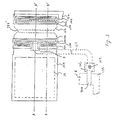
- the protective device is implemented on a P-type silicon substrate 21 (Figs. 3 and 4).
- N-type diffusion regions 11a and 11b of 100 ⁇ m (microns) in length are formed (Figs. 3 - 6) extending substantially in parallel to each other and with a gap of 4 ⁇ m (microns) therebetween and an N-type diffusion region 11c (Figs. 3 - 6) extending from a center portion of a left (outer) side of the region 11a and serving as the diffusion resistor R.
- These diffusion regions 11a, 11b and 11c are covered with a thin insulating film 23 of silicon dioxide, except for contact areas and the other surface of the protective device which is covered with a thick field insulating layer 22 of silicon dioxide.
- Polysilicon connecting layers 12a and 12b are electrically contacted with the N-type diffusion regions 11a and 11b, respectively, through contact holes 13a and 13b open in the thin insulating films 23 and extended on the upper surface of the thick insulating film 22, respectively.
- the contact holes 13a and 14b are of a slit shape extending along the outer edges of the N-type diffusion regions 11a and 11b, respectively, to a length almost equal to but less than the length of the diffusion regions 11a and 11b.
- the polysilicon connecting layer 12a is contacted with the region 11a through the entire length of the contact hole 13a and its two side portions are extended onto the nearby thick field insulating layer provided adjacently to and along the outer edge of the region 11a.
- the polysilicon connecting layer 12b is contacting with the N-type diffusion region 11b via the entire length of the contact hole 13b and extended onto the thick field insulating layer located adjacent to and along the outer edge of the region 11b.
- a polysilicon gate 12c is also formed simultaneously with the polysilicon layers 12a and 12b and forms a functional MOS transistor TR0 to be protected together with N-type source and drain regions 11e and 11d (Figs. 3 and 6).
- the silicon gate 12c is connected to an output end of the diffusion region 11c at a contact hole 13c.
- the surface of the substrate 21 with the polysilicon layers 12a, 12b and 12c is covered by an insulating layer 24 formed of silicon dioxide.
- An aluminum bonding pad 15a serving as an input terminal and an aluminum wiring 15b are formed on the insulating layer 24.
- the bonding pad 15a is connected to the two side portions of the polysilicon layer 12a on the thick field insulating layer through contact holes 14a formed in the insulating layer 24 (Figs. 3, 5 and 7) thereby achieving an electrical connection between the input terminal 15a and the N-type diffusion region 11a.
- the wiring 15b is connected to the polysilicon layer 12b through a contact hole 14b formed in the insulating layer 24 at the location over the thick insulating layer 22 (Figs.
- the surface of the substrate 21, excluding a bonding area 16 of the bonding pad 15a, is covered by an insulating layer 25, which may be formed of silicon dioxide, silicon nitride, phosphosilicate glass, or polyimid film.
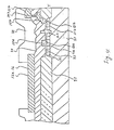
- the thick insulating layer 22 of a thickness of 300 to 900 nm (3000 to 9000 angstroms), favorably 400 to 700 nm (4000 to 7000 angstroms), is provided between the N-type diffusion regions 11a and 11b which form a punch-through type protective transistor TR1' with the insulating layer 22 therebetween.
- the punch-through voltage of this transistor TR1' is favorably in the range of 20 to 40 volts.
- the excess voltage propagates through the polysilicon layer 12a to the N-type region 11a.
- the N-type region 11a and the N-type region 11b supplied with the ground potential are spaced apart at a relatively narrow interval such as 4 ⁇ m (microns) via the part of the insulating layer 22, a depletion layer (not shown) extending from the N-type region 11a applied with the excess voltage reaching the N-type diffusion region 11b.
- the electrical path is achieved between the diffusion regions 11a and 11b to thereby discharge the excess voltage to the ground and suppress the voltage at the diffusion region 11a to less than a predetermined value.
- the diffusion regions 11a and 11b are spaced apart at an interval of about 4 ⁇ m (microns). However, this interval may be narrower than 4 ⁇ m (microns) when the integrated circuit is very sensitive to the excess voltage.
- the inner corners of the diffusion regions 11a and 11b are cut out as shown in Figs. 3 and 6 so that the interval between the diffusion regions 11a and 11b is lengthened at the end (side) portions, whereby undesired punch-through is prevented from occuring at the end portions of the interval at a voltage lower than the predetermined voltage.
- the resistor diffusion region 11c is extended from a control portion of the outer edge of the diffusion region 11a towards the bonding pad 15a to run away from the channel of the punch-through transistor TR1' and then bent to run under the bonding pad 15a in the direction normal to the current path of the punch-through transistor TR1', then the resistor diffusion region 11a is hardly affected by electric carriers generated at the channel region of the transistor TR1' by the excess voltage. Moreover, an area under the bonding pad 15a is utilized to form the resistor diffusion region 11c, and an area required by the protective device composed of the transistor TR1' and the resistor R can be reduced.
- the polysilicon connecting layers 12a and 12b are located between the bonding pad 15a and the region 11a and between the wiring 15b and the region 11b, respectively Therefore, even when the bonding pad 15a or the wiring 15b is heated and partially melted by the excess voltage applied to the bonding pad 15a, the melted aluminum is prevented from reaching the surface of the semiconductor substrate 21 due to the presence of the polysilicon layers 12a and 12b. Thus, so-called alloy-spike phenomenon by the melted aluminum can be effectively prevented.
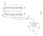
- Fig. 6 shows layout patterns of the N-type diffusion regions 11a, 11b, 11c, 11d and 11e, the polysilicon layers 12a, 12b and 12c and the contact holes 13a, 13b and 13c, whale Fig. 7 is a layout of the aluminum layer 15a and 15b with contact regions 14a and 14b.
- the protective device according to the present invention is provided with the diffusion region 11a spaced apart from the diffusion region 11b via the narrow distance such as 4 ⁇ m (microns) so that the excessive voltage is effectively discharged to the ground regardless of existence of another diffusion region which forms part of a circuit element of the functional circuit fabricated on the same substrate.
Landscapes
- Metal-Oxide And Bipolar Metal-Oxide Semiconductor Integrated Circuits (AREA)
- Protection Of Static Devices (AREA)
- Amplifiers (AREA)
- Semiconductor Integrated Circuits (AREA)
Claims (5)
- Schutzvorrichtung für eine Funktionsschaltung (TRO), die auf einem Halbleitersubstrat (21) eines ersten Leitungstyps ausgebildet ist, mit einem ersten und einem zweiten Bereich eines zweiten Leitungstyps (Fa, Fb), die auf einem Oberflächenbereich des Halbleitersubstrats (21) ausgebildet sind, wobei jeder der ersten und zweiten Bereiche eine erste und eine zweite Seite parallel zueinander aufweisen, die erste Seite des ersten Bereichs (11a) und die erste Seite des zweiten Bereichs (11b) einander gegenüber liegen und über einen Isolierbereich voneinander beabstandet sind, einer ersten Isolierschicht (24), die den Oberflächenteil des Halbleitersubstrats (21) abdeckt, einer Leitungsschicht (15a), die auf der ersten Isolierschicht in der Nähe der zweiten Seite des ersten Bereiches (11a) ausgebildet ist, wobei die Leitungsschicht (15a) mit einem externen Signal versorgt wird und elektrisch mit dem ersten Bereich (11a) verbunden ist, einem dritten Bereich (11c) des zweiten Leitungstyps, der auf dem Oberflächenteil des Halbleitersubstrats (21) gebildet ist, wobei der dritte Bereich (11c) mit einem Teil der zweiten Seite des ersten Bereiches (11a) an seinem einen Ende verbunden ist und sich von dort aus durch einen Bereich unterhalb der Leitungsschicht (2a) erstreckt, einer Verdrahtungsschicht (15b), die elektrisch mit dem zweiten Bereich (11b) verbunden ist und mit einem ersten Bezugspotential versorgt wird, und einer Einrichtung zur Verbindung eines gegenüberliegenden Endes des dritten Bereichs (11c) mit der Funktionsschaltung (TRO).
- Schutzvorrichtung nach Anspruch 1, wobei die Breite des Isolierbereichs etwa 4 µm (Mikron) oder weniger beträgt.
- Schutzvorrichtung nach Anspruch 1, wobei die Leitungsschicht (15a) mit dem ersten Bereich (11a) über eine erste Polysiliziumschicht (12a) verbunden ist, die über der zweiten Seite des ersten Bereiches (11a) gebildet ist, und wobei die Verdrahtungsschicht (15b) mit dem zweiten Bereich (11b) durch eine zweite Polysiliziumschicht (12b) verbunden ist, die über einer zweiten Seite des zweiten Bereichs (11b), gegenüber seiner ersten Seite ausgebildet ist.
- Schutzvorrichtung nach Anspruch 1, wobei eine Isoliersohicht (22) im Isolierbereich ausgebildet ist.
- Integrierte Schaltung mit einer Schutzvorrichtung nach Anspruch 1,
dadurch gekennzeichnet, daß der erste Bereich (11a) rechteckig ist und eine erste und eine zweite parallele Längsseite aufweist, der zweite Bereich (11b) rechteckig ausgebildet ist und eine erste und eine zweite parallele Längsseite aufweist, wobei die erste Seite des ersten rechteckigen Bereichs (11a) und die erste Seite des zweiten rechteckigen Bereichs (11b) voneinander parallel beabstandet sind, der dritte Bereich (11c) ein Widerstandsbereich ist und mit einem Teil der zweiten Seite des ersten Bereichs (11a) verbunden ist, mit einer zweiten Isolierschicht, die im wesentlichen die Oberfläche des Halbleitersubstrates abdeckt mit Ausnahme des ersten und zweiten rechteckigen Bereichen (11a, 11b) und des Widerstandsbereichs (11c), wobei die erste Isolierschicht dünner ist als die zweite Isolierschicht, die erste Polysiliziumschicht (12a) auf dem ersten rechteckigen Bereich (11a) parallel mit seiner zweiten Seite über der ersten und der zweiten Isolierschicht ausgebildet ist und mit dem ersten rechteckigen Bereich (11a) über ein Kontaktloch (13a), das in der ersten Isolierschicht ausgebildet ist, in Verbindung steht, wobei die zweite Polysiliziumschicht (12b) auf dem zweiten rechteckigen Bereich (11b) über die erste und die zweite Isolierschicht parallel mit der zweiten Seite des zweiten rechteckigen Bereichs (11b) ausgebildet ist und mit dem zweiten rechteckigen Bereich über ein Kontaktloch (13b), das in der ersten Isolierschicht ausgebildet ist, in Verbindung steht, eine dritte Isolierschicht, die die erste und die zweite Polysiliziumschichten abdeckt, wobei die Leitungsschicht (15a) eine erste Aluminiumschicht ist, die auf der dritten Isolierschicht und über einen Teil des ersten rechteckigen Bereichs (11a) und einen Teil des Widerstandsbereichs (11c) ausgebildet ist, wobei die erste Aluminiumschicht mit der ersten Polysiliziumschicht (12a) durch ein Kontaktloch (14a), das in der dritten Isolierschicht ausgebildet ist, in Verbindung steht, die Verdrahtungsschicht (15b) eine zweite Aluminiumschicht ist, die auf der dritten Isolierschicht ausgebildet ist und mit der zweiten Polysiliziumschicht (12b) über ein Kontaktloch (14b), das in der dritten Isolierschicht ausgebildet ist, in Verbindung steht, wobei ein Transistor in dem Substrat ausgebildet ist, und mit einer Einrichtung zur Verbindung eines Teils des Widerstandsbereichs mit dem Transistor.
Applications Claiming Priority (2)
| Application Number | Priority Date | Filing Date | Title |
|---|---|---|---|
| JP61118760A JPH065749B2 (ja) | 1986-05-22 | 1986-05-22 | 半導体装置 |
| JP118760/86 | 1986-05-22 |
Publications (2)
| Publication Number | Publication Date |
|---|---|
| EP0253105A1 EP0253105A1 (de) | 1988-01-20 |
| EP0253105B1 true EP0253105B1 (de) | 1993-03-17 |
Family
ID=14744380
Family Applications (1)
| Application Number | Title | Priority Date | Filing Date |
|---|---|---|---|
| EP87107503A Expired - Lifetime EP0253105B1 (de) | 1986-05-22 | 1987-05-22 | Integrierte Schaltung mit verbesserter Schutzvorrichtung |
Country Status (4)
| Country | Link |
|---|---|
| US (1) | US4819046A (de) |
| EP (1) | EP0253105B1 (de) |
| JP (1) | JPH065749B2 (de) |
| DE (1) | DE3784793T2 (de) |
Families Citing this family (15)
| Publication number | Priority date | Publication date | Assignee | Title |
|---|---|---|---|---|
| JP2626229B2 (ja) * | 1989-10-12 | 1997-07-02 | 日本電気株式会社 | 半導体入力保護装置 |
| US5066999A (en) * | 1989-10-23 | 1991-11-19 | Micron Technology, Inc. | Resistor under wirebond pad |
| US5121179A (en) * | 1990-10-08 | 1992-06-09 | Seiko Epson Corporation | Higher impedance pull-up and pull-down input protection resistors for MIS transistor integrated circuits |
| JPH03259561A (ja) * | 1990-03-09 | 1991-11-19 | Fujitsu Ltd | 半導体装置 |
| US5189638A (en) * | 1990-04-26 | 1993-02-23 | Mitsubishi Denki Kabushiki Kaisha | Portable semiconductor memory device |
| JPH04332163A (ja) * | 1991-05-02 | 1992-11-19 | Sony Corp | 半導体メモリ |
| US6002155A (en) * | 1993-02-12 | 1999-12-14 | Fujitsu Limited | Semiconductor integrated circuit with protection circuit against electrostatic breakdown and layout design method therefor |
| US5754380A (en) * | 1995-04-06 | 1998-05-19 | Industrial Technology Research Institute | CMOS output buffer with enhanced high ESD protection capability |
| US5572394A (en) * | 1995-04-06 | 1996-11-05 | Industrial Technology Research Institute | CMOS on-chip four-LVTSCR ESD protection scheme |
| US5637900A (en) * | 1995-04-06 | 1997-06-10 | Industrial Technology Research Institute | Latchup-free fully-protected CMOS on-chip ESD protection circuit |
| CN1099713C (zh) * | 1995-04-06 | 2003-01-22 | 工业技术研究院 | 用n边多边形单元布线的mos单元、多单元晶体管及ic芯片 |
| US5929491A (en) * | 1995-07-20 | 1999-07-27 | Siemens Aktiengesellschaft | Integrated circuit with ESD protection |
| TW308733B (de) * | 1995-07-20 | 1997-06-21 | Siemens Ag | |
| US6414341B1 (en) * | 1998-09-25 | 2002-07-02 | Nec Corporation | Input/output protective device |
| US7244992B2 (en) * | 2003-07-17 | 2007-07-17 | Ming-Dou Ker | Turn-on-efficient bipolar structures with deep N-well for on-chip ESD protection |
Family Cites Families (10)
| Publication number | Priority date | Publication date | Assignee | Title |
|---|---|---|---|---|
| JPS562663A (en) * | 1979-06-20 | 1981-01-12 | Mitsubishi Electric Corp | Input output protective device for semiconductor ic |
| JPS5715459A (en) * | 1980-07-01 | 1982-01-26 | Fujitsu Ltd | Semiconductor integrated circuit |
| JPS59107555A (ja) * | 1982-12-03 | 1984-06-21 | Fujitsu Ltd | 半導体装置 |
| JPS59224164A (ja) * | 1983-06-03 | 1984-12-17 | Hitachi Ltd | 半導体集積回路装置 |
| JPS6010765A (ja) * | 1983-06-30 | 1985-01-19 | Fujitsu Ltd | 半導体装置 |
| US4605980A (en) * | 1984-03-02 | 1986-08-12 | Zilog, Inc. | Integrated circuit high voltage protection |
| US4692781B2 (en) * | 1984-06-06 | 1998-01-20 | Texas Instruments Inc | Semiconductor device with electrostatic discharge protection |
| JPH0691196B2 (ja) * | 1984-07-25 | 1994-11-14 | 株式会社日立製作所 | 半導体装置 |
| JPS6144454A (ja) * | 1984-08-09 | 1986-03-04 | Fujitsu Ltd | 半導体装置 |
| US4656732A (en) * | 1984-09-26 | 1987-04-14 | Texas Instruments Incorporated | Integrated circuit fabrication process |
-
1986
- 1986-05-22 JP JP61118760A patent/JPH065749B2/ja not_active Expired - Lifetime
-
1987
- 1987-05-22 EP EP87107503A patent/EP0253105B1/de not_active Expired - Lifetime
- 1987-05-22 US US07/052,923 patent/US4819046A/en not_active Expired - Fee Related
- 1987-05-22 DE DE8787107503T patent/DE3784793T2/de not_active Expired - Fee Related
Also Published As
| Publication number | Publication date |
|---|---|
| JPS62274664A (ja) | 1987-11-28 |
| DE3784793T2 (de) | 1993-07-08 |
| EP0253105A1 (de) | 1988-01-20 |
| JPH065749B2 (ja) | 1994-01-19 |
| US4819046A (en) | 1989-04-04 |
| DE3784793D1 (de) | 1993-04-22 |
Similar Documents
| Publication | Publication Date | Title |
|---|---|---|
| KR100203054B1 (ko) | 개선된 정전기 방전 능력을 갖는 집적 회로 | |
| JP2699654B2 (ja) | トリガ電圧を低減したscr保護構造および回路 | |
| JP4017187B2 (ja) | 静電放電保護回路 | |
| KR0164908B1 (ko) | 보호 트랜지스터를 가진 반도체 장치 | |
| US5686751A (en) | Electrostatic discharge protection circuit triggered by capacitive-coupling | |
| US7183612B2 (en) | Semiconductor device having an electrostatic discharge protecting element | |
| US5903424A (en) | Method for protecting an integrated circuit against electro-static discharges | |
| KR100645039B1 (ko) | 정전기 방전 보호 소자 및 그 제조방법 | |
| EP0253105B1 (de) | Integrierte Schaltung mit verbesserter Schutzvorrichtung | |
| US5844280A (en) | Device for protecting a semiconductor circuit | |
| EP0415255B1 (de) | Schutzschaltung für eine Verwendung in einer integrierten Halbleiterschaltungsanordnung | |
| US4990984A (en) | Semiconductor device having protective element | |
| KR900005151B1 (ko) | 집적회로에 있어서의 보호장치 | |
| EP0202646B1 (de) | Eingangsschutzanordnung | |
| US6534834B1 (en) | Polysilicon bounded snapback device | |
| EP0198468B1 (de) | Schutzanordnung für eine integrierte Schaltung | |
| US4727405A (en) | Protective network | |
| US5521413A (en) | Semiconductor device having a solid metal wiring with a contact portion for improved protection | |
| KR100347397B1 (ko) | 반도체 집적회로용 입출력 보호 장치 | |
| KR0165897B1 (ko) | Mos 소자용 과전압 보호회로 | |
| KR100189036B1 (ko) | 반도체 디바이스 | |
| US6870227B1 (en) | Device for protecting against electrostatic discharge | |
| KR100645069B1 (ko) | 정전기 방전 보호 소자 및 그 제조방법 | |
| JP3017083B2 (ja) | 入出力保護回路 | |
| US5432369A (en) | Input/output protection circuit |
Legal Events
| Date | Code | Title | Description |
|---|---|---|---|
| PUAI | Public reference made under article 153(3) epc to a published international application that has entered the european phase |
Free format text: ORIGINAL CODE: 0009012 |
|
| 17P | Request for examination filed |
Effective date: 19870522 |
|
| AK | Designated contracting states |
Kind code of ref document: A1 Designated state(s): DE FR GB |
|
| 17Q | First examination report despatched |
Effective date: 19910723 |
|
| GRAA | (expected) grant |
Free format text: ORIGINAL CODE: 0009210 |
|
| AK | Designated contracting states |
Kind code of ref document: B1 Designated state(s): DE FR GB |
|
| REF | Corresponds to: |
Ref document number: 3784793 Country of ref document: DE Date of ref document: 19930422 |
|
| ET | Fr: translation filed | ||
| PLBE | No opposition filed within time limit |
Free format text: ORIGINAL CODE: 0009261 |
|
| STAA | Information on the status of an ep patent application or granted ep patent |
Free format text: STATUS: NO OPPOSITION FILED WITHIN TIME LIMIT |
|
| 26N | No opposition filed | ||
| PGFP | Annual fee paid to national office [announced via postgrant information from national office to epo] |
Ref country code: FR Payment date: 20000510 Year of fee payment: 14 |
|
| PGFP | Annual fee paid to national office [announced via postgrant information from national office to epo] |
Ref country code: GB Payment date: 20000517 Year of fee payment: 14 |
|
| PGFP | Annual fee paid to national office [announced via postgrant information from national office to epo] |
Ref country code: DE Payment date: 20000522 Year of fee payment: 14 |
|
| PG25 | Lapsed in a contracting state [announced via postgrant information from national office to epo] |
Ref country code: GB Free format text: LAPSE BECAUSE OF NON-PAYMENT OF DUE FEES Effective date: 20010522 |
|
| GBPC | Gb: european patent ceased through non-payment of renewal fee |
Effective date: 20010522 |
|
| PG25 | Lapsed in a contracting state [announced via postgrant information from national office to epo] |
Ref country code: FR Free format text: LAPSE BECAUSE OF NON-PAYMENT OF DUE FEES Effective date: 20020131 |
|
| PG25 | Lapsed in a contracting state [announced via postgrant information from national office to epo] |
Ref country code: DE Free format text: LAPSE BECAUSE OF NON-PAYMENT OF DUE FEES Effective date: 20020301 |