EP0253113A2 - Appareil d'entraînement pour le tennis - Google Patents
Appareil d'entraînement pour le tennis Download PDFInfo
- Publication number
- EP0253113A2 EP0253113A2 EP87107789A EP87107789A EP0253113A2 EP 0253113 A2 EP0253113 A2 EP 0253113A2 EP 87107789 A EP87107789 A EP 87107789A EP 87107789 A EP87107789 A EP 87107789A EP 0253113 A2 EP0253113 A2 EP 0253113A2
- Authority
- EP
- European Patent Office
- Prior art keywords
- ball
- arm
- training device
- ball holder
- axis
- Prior art date
- Legal status (The legal status is an assumption and is not a legal conclusion. Google has not performed a legal analysis and makes no representation as to the accuracy of the status listed.)
- Ceased
Links
Images


Classifications
-
- A—HUMAN NECESSITIES
- A63—SPORTS; GAMES; AMUSEMENTS
- A63B—APPARATUS FOR PHYSICAL TRAINING, GYMNASTICS, SWIMMING, CLIMBING, OR FENCING; BALL GAMES; TRAINING EQUIPMENT
- A63B69/00—Training appliances or apparatus for special sports
- A63B69/0073—Means for releasably holding a ball in position; Balls constrained to move around a fixed point, e.g. by tethering
- A63B69/0091—Balls fixed to a movable, tiltable or flexible arm
-
- A—HUMAN NECESSITIES
- A63—SPORTS; GAMES; AMUSEMENTS
- A63B—APPARATUS FOR PHYSICAL TRAINING, GYMNASTICS, SWIMMING, CLIMBING, OR FENCING; BALL GAMES; TRAINING EQUIPMENT
- A63B2208/00—Characteristics or parameters related to the user or player
- A63B2208/12—Characteristics or parameters related to the user or player specially adapted for children
Definitions
- the invention relates to a training device for tennis according to the preamble of claim 1.
- a tennis ball holding device is known (US Pat. No. 3,876,203), which essentially consists of a foot part from which a height-adjustable arm points upwards and to the side via a gimbal spring suspension.
- This arm carries a plate-shaped ball holder at the end into which a tennis ball can be inserted.
- the support arm or the ball receptacle In the event of a stroke on the statically held tennis ball, the support arm or the ball receptacle is hit at the same time, so that the support arm is caused to rotate and oscillate after a stroke.
- a rigid design of the return springs for the arm is not possible for practical reasons, since on the one hand the ball could not be knocked off in the desired manner and on the other hand the braking effect on the racket or the striker would be too great.
- the support arm clearly makes large swings and pendulum swings after one stroke until the upright basic position is restored. Because of the required height of the support arm, there is therefore a risk of injury for the already unsafe beginner.
- a reference to the quality of the blow or a properly executed striking technique cannot be taken from a position of the holding arm, since it swings back immediately after the blow with considerable rotary pendulum movements.
- the plate-shaped ball intake is also considered to be disadvantageous.
- Such a ball holder can only support the tennis ball from below, so that the position of the support arm or the arrangement of the ball holder is largely fixed and cannot be freely selected.
- Various striking techniques, such as for undercut balls cannot be practiced with the known device.
- a plate-shaped ball intake is mandatory Often large in their spatial extent, so that they are hit very early in a stroke or already together with the tennis ball. As a result, a significant part of the impact energy is not transmitted to the tennis ball, but to the ball holder and thus the holding device, in an undesirable manner. Because of the above disadvantages, such a device has not been able to establish itself in practice.
- a striking aid is also known (DE-GM 84 31 159), in which an angle lever carries a ball firmly connected at the end.
- the angle lever is connected on the bottom side with a hinge joint with a horizontal axis to a base plate.
- the horizontal axis is transverse to the direction of lay. After hitting the ball, the angle lever is struck on a rubber buffer at a distance, after which it springs back into its upright position and is ready for a new hit with its fixed ball.
- the object of the invention is to develop a generic training device so that the least possible reaction of the training device or the ball holder to a tennis shot and a tennis player performing the tennis shot, and thus the least possible influence on the striking technique by the device with little risk of injury to the exerciser is present.
- the training device consists of a support part with a relatively heavy base plate and a height-adjustable standpipe.
- a ball holder is movably connected to the standpipe and consists of an arm with a receptacle for a tennis ball attached to it at the end. A tennis ball can be knocked out of this shot with the help of a tennis racket.
- the ball holder or the movable arm is connected to the standpipe via a hinge joint, the joint axis lying horizontally transverse to the direction of impact.
- No elastic return elements for the ball holder are installed.
- the ball receptacle is designed as a U-shaped elastic clamp, the U-legs lying transversely to the stroke direction.
- the standpipe and thus the ball holder are adjusted to the desired height, so that the tennis ball is held in a suitable striking position by the U-shaped elastic clamp.
- the force of the blow ges is essentially transferred to the tennis ball in the desired manner.
- the ball holder itself either swings back to the tennis ball immediately due to the clamping force or is only slightly hit by the racket after the tennis ball has been knocked out of the ball holder. Since there are no spring return elements built in, the ball holder offers little resistance to the stroke. The ball holder swings away around the horizontal axis. The flight of the ball is therefore only slightly influenced by the ball holder, so that the striking technique can be controlled.
- the ball holder Since the ball holder only tilts away and does not strike back due to the lack of elastic return elements, there is practically no risk of injury to the exerciser or the risk of the tennis racket getting caught on the ball holder. Because of the U-shaped elastic clip as a ball holder, the tennis ball can also be held from above, so that its underside is free for undercut striking techniques.
- the ball holder be rotated about a horizontal pivot axis in addition to being supported via a vertical axis.
- the ball holder would not fold away as a result, but would act as a practically rigid element.
- this extreme case does not occur, with an unclean striking technique or deliberate strikes to the side, but also a force component occurs that acts laterally to the swivel plane, which means that the ball holder can counter the stroke with a greater counterforce. This is reduced by the fact that the ball holder can also be rotated about a vertical axis.
- this reduces the possible resistance and thus the risk of injury, and on the other hand the ball holder swivels in the direction of the stroke.
- This is in addition to the ball flight direction a way to recognize and correct the direction of the shot and possible errors in the striking technique.
- the ball holder is attached above the standpipe (claim 8)
- the ball holder remains in the struck direction after it has tilted away, so that permanent control is possible here. This makes it possible to see, for example, whether the straight-ahead phase at the ball position is too short and the club is swung out too early.
- Claim 4 specifies a simple, inexpensive and stable design of a hinge joint as a mounted roller with which the arm is firmly connected.
- the ball receptacle should be approximately above or below the bearing point, at least seen transversely to the direction of impact. This results in a good introduction of force into the swivel bearing (even when the arm is bent).
- the arched shape of the support arm as claimed in claim 6 it is advantageously achieved that the arm itself cannot be hit with the racket, for example the racket edge, but in the desired manner first the ball and then the ball pick-up is hit only with the racket covering. Furthermore, it is excluded by the claimed form that the racket on Ball holder imposed or overall the stroke is obstructed in its direction of movement.
- the arm can also be designed so that it extends in the direction of impact laterally away from its bearing point.
- Such an embodiment of an arm or ball holder is particularly useful for training the impact technique or the impact technique for high balls.
- the ball holder If the ball holder is to stand up in its initial position, i. H. the swivel axis is below the ball holder, it is necessary to hold the ball holder in this position before the shot.
- the weight is appropriately dimensioned (with the ball inserted), the center of gravity of the ball holder is on the swivel axis side towards the player and the ball holder holds itself in this position. This displacement should only be slight so that the ball holder tilts slightly when struck.
- a favorable design and dimensioning results according to claim 9 when the ball holder is approximately above the axis of rotation and the pivot axis slightly in the direction of impact, for. B. is offset by about a ball width in the direction of impact.
- Claim 10 specifies an expedient embodiment of the standpipe for a hanging attachment of the ball holder.
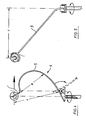
- a training device 1 which consists essentially of a base plate 2, a height-adjustable standpipe 3 and a ball holder 4.
- the ball holder 4 in turn consists of an arm 5 which carries a ball holder 6 for a tennis ball 7 on its upper end side and is connected to the standpipe via a bearing element 8.
- the bearing element is constructed from an approximately horizontal support plate (9) which carries a bearing pin 10 which projects downwards and which engages in the standpipe 3 as an axis of rotation, as a result of which a rotational movement about the standpipe 3 is possible (arrow 11).
- a horizontally mounted roller 13 is attached to the bearing pin 10 in the direction of impact (arrow 12), the bearing axis 14 being transverse to the direction of impact (arrow 12).
- the lower part of the arm 5 is firmly connected to the roller.
- the end part 15 of the arm 5 is supported on the support plate 9 in its upward position.
- the arm 5 is bulged in the direction of the stroke, the being given diameter A be about 360 mm and B about 250 mm.
- the tennis ball 7 or the ball receptacle 6 are offset from the pivot axis 14, as a result of which the ball holder 4 remains in its upright position, but can tilt away in the direction of the stroke (arrow 16 or dashed ball holder 17).
- the execution of the ball holder 6 can be seen as a U-shaped bracket.
- soft plastic could be used as the material for this.
- the training device 1 shown has the following function:
- the training device Before a stroke, the training device is brought into the position shown in FIG. 1 by pivoting the ball holder 4 upward and inserting a tennis ball 7. The ball 7 is then knocked away, causing it to fly out of the ball receptacle 6. At the same time or shortly thereafter, the ball holder 6 is also hit by the racket covering, as a result of which the ball holder 4 folds downward about the bearing axis 14. If a force component was contained in the stroke at an angle to the folding direction, the ball holder 4 rotates correspondingly about the bearing axis 10 and remains essentially in the folded-down position in the direction of the stroke. In order to mitigate the impact of the folded-down ball holder 4, damping means which act as far as possible without a restoring force can be used.
- the ball holder 4 Before a new stroke, the ball holder 4 is to be erected again and equipped with a tennis ball 7.
- a base plate 2 and a height-adjustable standpipe 3 are also provided in the embodiment according to FIG. 3.
- This standpipe is bent downward again in its upper region 18 and a bearing element 8 and a ball holder 4 according to FIG. 1 are suspended in the region 18.
- this embodiment is similar to that in Fig. 1, except that the ball holder 4 folds up here.
- a locking device (not shown) could be provided, which catches the ball holder in the folded-up position and holds it until a new stroke.
- this is normally not necessary since the ball holder 4 itself is relatively light and, when it swings back due to gravity, can neither hinder the blow nor lead to injuries, since it does not contain any resilient spring means.
- the embodiment according to FIG. 1 is particularly intended for straight basic strokes and overcut balls, while the embodiment according to FIG. 3 is also suitable for straight basic strokes and undercut balls.
- a third embodiment is shown, which is particularly suitable for high balls and serve training.
- the ball holder 4 is thus mounted correspondingly high above the head height of a player.
- the ball receptacle 6 is also a U-shaped spring clip in which the tennis ball is held.
- this third embodiment corresponds to the embodiments according to FIGS. 1 and 3.
- the ball receptacle 6 is also above or below in a front view or in the direction of impact of the bearing elements 8
- this third embodiment differs in that the arm 5 is guided to the side in a front view (FIG. 5). This results in a more optimal ballage, especially for serve training.
- the ball holder 4 Due to the lateral displacement, the ball holder 4 can also be rotated in a stroke. However, this is not critical in the case of a stroke in a high position, since then the racket is guided downwards anyway and neither the player nor the racket are influenced by the rotary movement.
- the invention provides a training device for tennis that is very inexpensive and that practically no risk of injury enables beginners to learn the tennis ball technique on the static ball. A special area of application is therefore seen in schools to familiarize students with the beginnings of tennis tennis.
Landscapes
- Health & Medical Sciences (AREA)
- General Health & Medical Sciences (AREA)
- Physical Education & Sports Medicine (AREA)
- Golf Clubs (AREA)
Applications Claiming Priority (2)
| Application Number | Priority Date | Filing Date | Title |
|---|---|---|---|
| DE19863623957 DE3623957A1 (de) | 1986-07-16 | 1986-07-16 | Trainingsgeraet fuer tennis |
| DE3623957 | 1986-07-16 |
Publications (2)
| Publication Number | Publication Date |
|---|---|
| EP0253113A2 true EP0253113A2 (fr) | 1988-01-20 |
| EP0253113A3 EP0253113A3 (en) | 1990-04-25 |
Family
ID=6305265
Family Applications (1)
| Application Number | Title | Priority Date | Filing Date |
|---|---|---|---|
| EP87107789A Ceased EP0253113A3 (en) | 1986-07-16 | 1987-05-29 | Training apparatus for tennis |
Country Status (2)
| Country | Link |
|---|---|
| EP (1) | EP0253113A3 (fr) |
| DE (1) | DE3623957A1 (fr) |
Cited By (3)
| Publication number | Priority date | Publication date | Assignee | Title |
|---|---|---|---|---|
| WO1995032768A1 (fr) * | 1994-05-26 | 1995-12-07 | Wayne Charles Cowley | Support pour une balle utilisee dans un jeu |
| US5797810A (en) * | 1996-01-25 | 1998-08-25 | Sandoval; George R. | Batting practice device |
| AU697105B2 (en) * | 1995-05-15 | 1998-09-24 | Robert Michael Gleeson | Tennis solo trainer |
Families Citing this family (2)
| Publication number | Priority date | Publication date | Assignee | Title |
|---|---|---|---|---|
| DE29902879U1 (de) | 1999-02-18 | 1999-05-06 | Bannwarth, Roland, 79650 Schopfheim | Ballspielvorrichtung |
| CN104841114A (zh) * | 2014-02-15 | 2015-08-19 | 韦敬彪 | 实战型羽毛球综合技术训练器 |
Family Cites Families (8)
| Publication number | Priority date | Publication date | Assignee | Title |
|---|---|---|---|---|
| DE8431159U1 (de) * | 1985-01-24 | Liao, Leon, Changhwa | Schlaghilfe | |
| GB240652A (en) * | 1924-10-11 | 1925-10-08 | Harold Penn Gaskell | Apparatus for use in teaching or practising lawn-tennis |
| US2272765A (en) * | 1940-04-24 | 1942-02-10 | Beeson John Dalton | Game practice device |
| US3341200A (en) * | 1964-03-25 | 1967-09-12 | Elden W Brandley | Batting practice apparatus with ground engaging and inclining support |
| FR2232339A1 (en) * | 1973-06-08 | 1975-01-03 | Lamole Jean | Tennis practice device with ball on pivoting arm - arm is vertically adjustable and springs back to vertical |
| US3876203A (en) * | 1974-04-04 | 1975-04-08 | Philip Gold | Device for use in practicing tennis strokes |
| US4089521A (en) * | 1976-08-25 | 1978-05-16 | Berst Theodore H | Tennis stroke trainer |
| DE2846861A1 (de) * | 1978-10-27 | 1980-05-08 | Erhart Enterlein Fa | Tennisuebungsgeraet |
-
1986
- 1986-07-16 DE DE19863623957 patent/DE3623957A1/de active Granted
-
1987
- 1987-05-29 EP EP87107789A patent/EP0253113A3/de not_active Ceased
Cited By (3)
| Publication number | Priority date | Publication date | Assignee | Title |
|---|---|---|---|---|
| WO1995032768A1 (fr) * | 1994-05-26 | 1995-12-07 | Wayne Charles Cowley | Support pour une balle utilisee dans un jeu |
| AU697105B2 (en) * | 1995-05-15 | 1998-09-24 | Robert Michael Gleeson | Tennis solo trainer |
| US5797810A (en) * | 1996-01-25 | 1998-08-25 | Sandoval; George R. | Batting practice device |
Also Published As
| Publication number | Publication date |
|---|---|
| EP0253113A3 (en) | 1990-04-25 |
| DE3623957C2 (fr) | 1988-12-01 |
| DE3623957A1 (de) | 1988-02-04 |
Similar Documents
| Publication | Publication Date | Title |
|---|---|---|
| DE3034323C2 (de) | Trainingsgeraet fuer ballspiele | |
| DE2547756A1 (de) | Trainiergeraet zum schlagen von baellen | |
| DE2506345A1 (de) | Spielfigur, insbesondere gliederpuppe | |
| EP3169413A1 (fr) | Appareil d'entraînement au tennis | |
| DE19521493C1 (de) | Vorrichtung für das Erlernen und Training eines effizienten Golfschwungs | |
| EP0210539B1 (fr) | Appareil pour jouer à la balle avec une parois de rebond fixée sur un support portatif | |
| EP0253113A2 (fr) | Appareil d'entraînement pour le tennis | |
| EP2760553A1 (fr) | Procédé et dispositif d'entraînement au lancer | |
| EP1728536B1 (fr) | Appareil d'entraînement pour le tennis | |
| DE3413247A1 (de) | Rueckgabewand fuer ballspiele | |
| EP2474344B1 (fr) | Appareil d'entraînement pour le système de combat Wing Chun | |
| DE3409756A1 (de) | Fahrradaehnlicher hometrainer | |
| DD150432A5 (de) | Verfahren und anlage zum werfen eines balls | |
| WO1985004336A1 (fr) | Paroi d'impact pour une installation de ramassage de balles de tennis | |
| DE19630820C2 (de) | Vorrichtung zum Trainieren der Körperhaltung und der Körperbewegung eines Golfspielers | |
| EP0035253A1 (fr) | Dispositif d'entraînement pour la technique du tennis | |
| DE102014018105B4 (de) | Golfübungseinrichtung | |
| DE4412500B4 (de) | Trainingsgerät | |
| WO1986005109A1 (fr) | Procede et dispositif permettant le tir ajuste de ballons de football | |
| DE2846861A1 (de) | Tennisuebungsgeraet | |
| DE2807743A1 (de) | Sportgeraet zum erlernen des schmetterschlages beim ballspielen | |
| DE1145069B (de) | Zielvorrichtung fuer Ballspiele, insbesondere Golftrainingsschlaege, bei welchen der Ball von einer Abschlagstelle auf ein ihn fangendes Netz geschlagen, gestossen bzw. geworfen wird | |
| DE2911146B2 (de) | Tennistechniktrainer | |
| DE1815248A1 (de) | Vorrichtung zum UEben des Schlaegerschwingens beim Golfspiel | |
| DE3629282A1 (de) | Ballwurfmaschine fuer tennisbaelle |
Legal Events
| Date | Code | Title | Description |
|---|---|---|---|
| PUAI | Public reference made under article 153(3) epc to a published international application that has entered the european phase |
Free format text: ORIGINAL CODE: 0009012 |
|
| AK | Designated contracting states |
Kind code of ref document: A2 Designated state(s): AT BE DE ES FR GB IT NL |
|
| PUAL | Search report despatched |
Free format text: ORIGINAL CODE: 0009013 |
|
| AK | Designated contracting states |
Kind code of ref document: A3 Designated state(s): AT BE DE ES FR GB IT NL |
|
| 17P | Request for examination filed |
Effective date: 19901001 |
|
| 17Q | First examination report despatched |
Effective date: 19910830 |
|
| STAA | Information on the status of an ep patent application or granted ep patent |
Free format text: STATUS: THE APPLICATION HAS BEEN REFUSED |
|
| 18R | Application refused |
Effective date: 19920224 |