EP0253133A2 - Innenzahnrad-Hydraulikpumpe - Google Patents
Innenzahnrad-Hydraulikpumpe Download PDFInfo
- Publication number
- EP0253133A2 EP0253133A2 EP87108293A EP87108293A EP0253133A2 EP 0253133 A2 EP0253133 A2 EP 0253133A2 EP 87108293 A EP87108293 A EP 87108293A EP 87108293 A EP87108293 A EP 87108293A EP 0253133 A2 EP0253133 A2 EP 0253133A2
- Authority
- EP
- European Patent Office
- Prior art keywords
- insert
- pump
- gear
- pump according
- gears
- Prior art date
- Legal status (The legal status is an assumption and is not a legal conclusion. Google has not performed a legal analysis and makes no representation as to the accuracy of the status listed.)
- Granted
Links
Images

Classifications
-
- F—MECHANICAL ENGINEERING; LIGHTING; HEATING; WEAPONS; BLASTING
- F04—POSITIVE - DISPLACEMENT MACHINES FOR LIQUIDS; PUMPS FOR LIQUIDS OR ELASTIC FLUIDS
- F04C—ROTARY-PISTON, OR OSCILLATING-PISTON, POSITIVE-DISPLACEMENT MACHINES FOR LIQUIDS; ROTARY-PISTON, OR OSCILLATING-PISTON, POSITIVE-DISPLACEMENT PUMPS
- F04C2/00—Rotary-piston machines or pumps
- F04C2/08—Rotary-piston machines or pumps of intermeshing-engagement type, i.e. with engagement of co-operating members similar to that of toothed gearing
- F04C2/10—Rotary-piston machines or pumps of intermeshing-engagement type, i.e. with engagement of co-operating members similar to that of toothed gearing of internal-axis type with the outer member having more teeth or tooth-equivalents, e.g. rollers, than the inner member
- F04C2/101—Rotary-piston machines or pumps of intermeshing-engagement type, i.e. with engagement of co-operating members similar to that of toothed gearing of internal-axis type with the outer member having more teeth or tooth-equivalents, e.g. rollers, than the inner member with a crescent-shaped filler element, located between the inner and outer intermeshing members
Definitions
- the invention refers to a hydraulic internal gear pump, comprising an internally toothed crown gear and an externally toothed driving gear which are mounted for an axial rotation within a suitable housing, the internally toothed crown gear meshing with the externally toothed driving gear, and being provided with inserts located in the region where the gears are apart from each other, and which operate by contacting the teeth of said gears, whereby the suction (low pressure) zone is separated from the delivery (high pressure) zone of the pump.
- the sealing inserts In the pumps of known type, the sealing inserts generally are all arranged at the delivery side of the pump, where they act both on the externally toothed gear and on the internally toothed crown gear. It ensues that any friction produced by the sealing inserts and the heat resulting therefrom will subject the pump to unbalanced localized stresses, which impair the pump operation at any high pressure value.
- Some embodiments are also known, according to which the sealing inserts operate in substantially opposite positions with respect to the axes of rotation of the gears, thus solving the problem of friction and heat distribution to the pump components. These embodiments however have the drawback of producing a friction having a very high value, since each sealing insert acts on both of the gears, at the suction side and at the delivery side of the pump.
- the invention suggests a hydraulic pump with internal gears, in which the sealing inserts are so made that they act only on a section of the externally toothed gear, at the suction side, and only on a section of the internally toothed gear, at the delivery side, so that the advantage arising from a friction having a limited value is added to the advantage of the proper distribution to the pump components of the heat resulting from any such friction.
- a first insert in the suction zone of the pump a first insert is provided, which is fixedly secured to the static portion of the pump, and is so constructed that also thanks to a suitable rotatable support for the externally toothed gear, this gear will operate, owing to the pressure in the delivery circuit, by intimately contacting the inward side of the said stationary insert.
- a second insert is provided on the extension of the body of the said stationary insert and is tightly connected thereto, the said second insert being movable, and being positively sealed in an intimate manner against a sufficient number of teeth of the internally toothed crown gear by the bias of a preload spring and by the pressure in the delivery circuit of the pump.
- only one sealing insert is provided, which is intermediately fulcrumed about a stationary pin parallel to the gear axes, and which is so long as to have its extremities respectively reaching the delivery zone and the suction zone of the pump.
- At least one preload spring urges against the crown gear the arm of the insert which is turned toward the delivery zone, and which is so urged also by the pressure in the delivery circuit, since the said arm is to a suitable extent longer than the opposite arm which operates by contacting the externally toothed gear.
- Compensating shoes may be provided on at least one of the active end sections of the said movable or swingable sealing insert.
- the shaft 5 shall be rotatably supported in such a manner that any radial stresses to which the gear wheel 4 is subjected due to the high pressure in the delivery circuit of the pump, will be not counterbalanced entirely, in view of the fact that the invention, as it will be more fully stated later, counts also on such stresses in order to assure the proper operation of the pump at any high pressure.
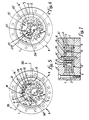
- references A and M and by dash-and-dot lines there are respectively designated the apertures through which the suction and the delivery duct formed, for example, in one of the cover plates 6 or 6 ⁇ , open into the hollow space defined by the gears 3,4, respectively upstream and downstream of the area in which the said gears are seen to be mutually in mesh.
- the shaft 5 for the gear 4 is driven in rotation in the fixed direction indicated by arrow F.
- a moon crescent-shaped insert 9 extending from the suction zone to the delivery zone, is provided within the hollow space defined by the gears 3,4, and is fixedly secured to static components of the pump, in accordance with any one of the embodiments which by way of examples will be disclosed hereinafter.
- the inward side of insert 9 is so shaped that a section thereof, as shown at 109, situated at a short distance from the suction zone A of the pump, will result into contact with a sufficient number of teeth of the gear wheel 4.
- the rest of the profile of insert 9 is preferably suitably spaced both from the said gear 4 and from the crown gear 3, but for a possible section designated by 209.
- the pressure difference between the zones A and M and the dynamic reaction between the gears 3,4 will subject the gear wheel 4 to such a radial stress having a component in the direction of arrow F1, that an intimate contact of said gear with the section 109 of insert 9 is assured, and the separation of said zones A and M is guaranteed, even at any high pressure value in the delivery circuit of the pump.
- the shaft 5 will be rotatably supported in such a manner as to aid the aforesaid condition, for example, by the provision of a proper play in correspondence of the shaft supports.
- the insert 9 could operate by contacting the gear wheel 4 with the interposition of a shoe (see hereinafter) tightly secured in a removable manner to the inward side of insert 9, so as to form the previously disclosed sealing surface 109.
- the insert 9 may be made from any material or composition of materials fit for the purpose for which the said insert is intended. As shown in figure 2, the insert 9 is secured by means of a pair of pins 10,10 ⁇ to the cover plates 6,6 ⁇ of the pump.
- the pins are passed through the wear plates 11,11 ⁇ which perform their function by contacting the gears of the pump, and which are located underneath the cover plates 6,6 ⁇ with the interposition of annular seals 12,12 ⁇ having in plan view a configuration of the type as shown by way of an example in figure 1, such as to delimit at their interior sealed areas into which the pressure of the delivery circuit of the pump is led through bores 13,13 ⁇ made in the said wear plates, so that the said wear plates will be axially urged against the gears 3,4 whereby to assure the seal and automatically adjust the wear to which the wear plates are subjected.
- the insert 9 may be formed of one piece with one of the wear plates 11,11 ⁇ or, according to the modified embodiment shown in figure 3, the said insert 9 may be formed of one piece with the pump casing 1 ⁇ incorporating the bottom cover plate 6.
- the pump will be provided only with the wear plate 11 ⁇ and the relative cover plate 6 ⁇ .
- the plates 11,11 ⁇ will have a thickness fit for the use for which they are intended, even not proportional to the thickness shown in the drawings.
- the insert 9 may be removably secured by means, for example, of screws, to one or both of the wear plates 11,11 ⁇ .
- the outward side of the end section of insert 9, which terminates in correspondence of the delivery zone M of the pump, is shaped as shown at 309 or in any other suitable manner, such that with the said end section there can be associated under sealing conditions and with the possibility of an outward movement, an additional insert 14 having its outward side shaped as shown at 114, in such a manner that it will intimately operate on a sufficient number of teeth of the crown gear 3 so as to affect them throughout their depth, and that between the insert 14 and the end section 309 there will be a small cavity 15 which is fluid-tight relative to the low pressure zone A, and is connected in any suitable manner, for example, to ducts, such that the pressure in the delivery circuit M will flow into the said cavity, whereby the said pressure will guarantee the required sealing of 14 against 3.
- a small preload spring 16 for example of the leaf type, received in a housing 17 formed between the components 14 and 309, guarantees the required sealing of insert 14 against the crown gear 3. It is evident that since the insert 9 is stationary, it is not adversely conditioned by the movements of insert 14. Consequently, also the relative movements of gears 3,4 do not impair the performance of the sealing inserts.
- the friction areas of inserts 9 and 14 are widely apart from each other, in substantially diametrically opposite positions with respect to the gear wheel 4. Therefore, any heat generated at the said friction areas 109 and 114 is evenly distributed to the pump assembly, thus avoiding any localized stresses which instead occur in the pumps of known type. This condition guarantees a safe operation of the pump even at any high pressure in the delivery circuit M.
- the insert 9 ⁇ is of a length which is substantially limited to the length of the sealing surface 109 and is fixedly secured to stationary components of the pump, for example according to one of the possibilities as disclosed in connection with the embodiment shown in figure 1.
- the end of insert 9 ⁇ which is turned toward the high pressure zone, cooperates with the associated end section of an additional insert 19 which is intermediately fulcrumed about a pin 20 fixedly secured to the cover plates 6-6 ⁇ and parallel to shaft 5, the axis of said pin being the center of the said articulated surfaces 18, the tight connection of which is ensured by the provision of a linear seal 21.
- insert 19 is so shaped that it will intimately contact a sufficient number of teeth of the crown gear 3, against which it is urged by the bias of a preload spring 16 ⁇ and by the pressure in the delivery zone M of the pump.
- the insert 19 can operate on the crown gear 3 either by directly contacting same or with the interposition of a shoe 22 made of any suitable material, and which can be easily replaced whenever it is worn out.
- the shoe 22 can be removably secured to insert 19, for example, by means of screws, or, as shown in figure 5, it can be associated with the said insert so as to be allowed to perform an articulated movement around an axis parallel to the fulcrum 20, whereby to uniformly adapt itself to the crown gear 3 even when the angle of incidence of insert 19 with this crown gear changes.
- the stationary insert 9 has been eliminated and replaced with the insert 19 ⁇ which is now so sized that it has its extremities reaching the delivery zone M and the suction zone A respectively, and which is intermediately fulcrumed about a pin 20 ⁇ , similarly to the embodiment shown in figure 5.
- the arm 119 ⁇ of insert 19 ⁇ which is turned toward the delivery side is to a suitable extent longer than the opposite arm 219 ⁇ which is turned toward the suction side A, the whole in such a manner that the action of the pressure in the delivery circuit will force the said insert to turn in anti-clockwise direction as viewed in figure 6, thus assuring the required contact of 109 ⁇ with 3 and of 209 ⁇ with 4.
- Numeral 16 ⁇ denotes a preload spring which guarantees the fluid-tight cooperation of insert 19 ⁇ with the gears in the initial step of starting the pump.
- this insert may work on at least one of the two gears or on both, with the interposition of a compensating shoe.
- a shoe 23 is arranged on the arm 219 ⁇ of insert 19 ⁇ with the interposition of at least one seal 24 and an expanding elastic means 25, as well as in such a manner that also the pressure in the delivery circuit by penetrating between a portion of members 23,219 ⁇ , will guarantee the steady cooperation of said shoe with the externally toothed gear.
- the surface of these inserts which does not contact the gears 3,4 may be suitably finned and/or roughened.
Landscapes
- Engineering & Computer Science (AREA)
- Mechanical Engineering (AREA)
- General Engineering & Computer Science (AREA)
- Rotary Pumps (AREA)
- Details And Applications Of Rotary Liquid Pumps (AREA)
Priority Applications (1)
| Application Number | Priority Date | Filing Date | Title |
|---|---|---|---|
| AT87108293T ATE60825T1 (de) | 1986-06-18 | 1987-06-09 | Innenzahnrad-hydraulikpumpe. |
Applications Claiming Priority (2)
| Application Number | Priority Date | Filing Date | Title |
|---|---|---|---|
| IT1249986 | 1986-06-18 | ||
| IT12499/86A IT1189767B (it) | 1986-06-18 | 1986-06-18 | Pompa idraulica ad ingranaggi interni capace di operare a pressioni an che molto elevate |
Publications (3)
| Publication Number | Publication Date |
|---|---|
| EP0253133A2 true EP0253133A2 (de) | 1988-01-20 |
| EP0253133A3 EP0253133A3 (en) | 1988-08-17 |
| EP0253133B1 EP0253133B1 (de) | 1991-02-06 |
Family
ID=11140883
Family Applications (1)
| Application Number | Title | Priority Date | Filing Date |
|---|---|---|---|
| EP87108293A Expired EP0253133B1 (de) | 1986-06-18 | 1987-06-09 | Innenzahnrad-Hydraulikpumpe |
Country Status (4)
| Country | Link |
|---|---|
| EP (1) | EP0253133B1 (de) |
| AT (1) | ATE60825T1 (de) |
| DE (1) | DE3767934D1 (de) |
| IT (1) | IT1189767B (de) |
Cited By (5)
| Publication number | Priority date | Publication date | Assignee | Title |
|---|---|---|---|---|
| GB2299134A (en) * | 1995-03-23 | 1996-09-25 | Sauer Sundstrand Ltd | Internal gear pump |
| WO1998025029A1 (en) * | 1996-12-03 | 1998-06-11 | Danfoss A/S | Motor pump unit |
| GB2323636A (en) * | 1997-03-27 | 1998-09-30 | Unisia Jecs Corp | Compound gear pump and engine hydraulic circuits therewith |
| US6425747B2 (en) * | 1999-12-08 | 2002-07-30 | Luk Lamellen Und Kupplungsbau Gmbh | Gearing with mating internal and spur gears |
| WO2014060137A3 (de) * | 2012-10-19 | 2014-08-28 | Robert Bosch Gmbh | Innenzahnradpumpe für eine hydraulische fahrzeugbremsanlage |
Family Cites Families (6)
| Publication number | Priority date | Publication date | Assignee | Title |
|---|---|---|---|---|
| DE2114874A1 (de) * | 1971-03-27 | 1972-10-12 | Dowty Technical Developments Ltd., Brockhampton, Cheltenham (Großbritannien) | Hydraulische Verdrängungspumpe |
| DE2300484A1 (de) * | 1973-01-05 | 1974-07-18 | Otto Eckerle | Hochdruck-zahnradpumpe |
| DE2533646C2 (de) * | 1975-07-28 | 1986-04-17 | Otto Sion Wallis Eckerle | Hochdruck-Zahnradpumpe oder -motor |
| DE2641278A1 (de) * | 1976-09-14 | 1978-03-16 | Voith Getriebe Kg | Innenzahnradpumpe |
| GB1594942A (en) * | 1978-01-11 | 1981-08-05 | Smiths Industries Ltd | Gear pumps |
| DE2943768A1 (de) * | 1979-10-30 | 1981-05-14 | Breinlich, Richard, Dr., 7120 Bietigheim-Bissingen | Innenzahnrad - motoren oder pumpen - aggregat |
-
1986
- 1986-06-18 IT IT12499/86A patent/IT1189767B/it active
-
1987
- 1987-06-09 EP EP87108293A patent/EP0253133B1/de not_active Expired
- 1987-06-09 DE DE8787108293T patent/DE3767934D1/de not_active Expired - Lifetime
- 1987-06-09 AT AT87108293T patent/ATE60825T1/de not_active IP Right Cessation
Cited By (9)
| Publication number | Priority date | Publication date | Assignee | Title |
|---|---|---|---|---|
| GB2299134A (en) * | 1995-03-23 | 1996-09-25 | Sauer Sundstrand Ltd | Internal gear pump |
| GB2299134B (en) * | 1995-03-23 | 1998-06-24 | Sauer Sundstrand Ltd | Internal gear pump |
| WO1998025029A1 (en) * | 1996-12-03 | 1998-06-11 | Danfoss A/S | Motor pump unit |
| KR100391007B1 (ko) * | 1996-12-03 | 2003-07-12 | 댄포스 아/에스 | 모터 펌프 유니트 |
| GB2323636A (en) * | 1997-03-27 | 1998-09-30 | Unisia Jecs Corp | Compound gear pump and engine hydraulic circuits therewith |
| GB2323636B (en) * | 1997-03-27 | 1999-05-12 | Unisia Jecs Corp | Compound gear pumps and engine hydraulics circuits using same |
| US6045338A (en) * | 1997-03-27 | 2000-04-04 | Unisia Jecs Corporation | Compound gear pumps and engine hydraulic circuits using same |
| US6425747B2 (en) * | 1999-12-08 | 2002-07-30 | Luk Lamellen Und Kupplungsbau Gmbh | Gearing with mating internal and spur gears |
| WO2014060137A3 (de) * | 2012-10-19 | 2014-08-28 | Robert Bosch Gmbh | Innenzahnradpumpe für eine hydraulische fahrzeugbremsanlage |
Also Published As
| Publication number | Publication date |
|---|---|
| EP0253133A3 (en) | 1988-08-17 |
| IT1189767B (it) | 1988-02-04 |
| IT8612499A1 (it) | 1987-12-18 |
| ATE60825T1 (de) | 1991-02-15 |
| EP0253133B1 (de) | 1991-02-06 |
| DE3767934D1 (de) | 1991-03-14 |
| IT8612499A0 (it) | 1986-06-18 |
Similar Documents
| Publication | Publication Date | Title |
|---|---|---|
| US3994635A (en) | Scroll member and scroll-type apparatus incorporating the same | |
| DK146573B (da) | Hydraulisk, omstyrbar tandhjulsmotor eller -pumpe | |
| US4472123A (en) | Internal gear machine with segmented filler members | |
| KR890010424A (ko) | 스크롤 압축기 | |
| GB2032529A (en) | Rotary positive-displacement fluidmachines | |
| GB1593445A (en) | Scroll-type orbiting positive fluid-displacement apparatus | |
| US2816512A (en) | Pressure loaded gear pump | |
| US3748063A (en) | Pressure loaded gear pump | |
| US2832293A (en) | Vane pump | |
| US4416598A (en) | Rotary vane pump with pressure biased flow directing end plate | |
| CA1282755C (en) | Drive system for the orbiting scroll of a scroll type fluid compressor | |
| US5593295A (en) | Scroll compressor construction having an axial compliance mechanism | |
| EP0253133B1 (de) | Innenzahnrad-Hydraulikpumpe | |
| JPS58118376A (ja) | メカニカルシ−ル | |
| US3887310A (en) | Hydraulic pump/motor with hydrostatically balanced rotors | |
| US3131643A (en) | Engine | |
| US3539282A (en) | Gear pump or motor | |
| US3083645A (en) | Gear pump or the like | |
| US4813856A (en) | Balanced rotary valve plate for internal gear device | |
| JPH11257251A (ja) | ポンプ | |
| US3912427A (en) | High pressure gear pump | |
| US4177025A (en) | High-pressure rotary fluid-displacing machine | |
| US2759426A (en) | Rotary pump | |
| US3002464A (en) | Rotary gear pump, bearings and sealing means therefor | |
| JPS6114490A (ja) | 回転容積型流体圧力機 |
Legal Events
| Date | Code | Title | Description |
|---|---|---|---|
| PUAI | Public reference made under article 153(3) epc to a published international application that has entered the european phase |
Free format text: ORIGINAL CODE: 0009012 |
|
| AK | Designated contracting states |
Kind code of ref document: A2 Designated state(s): AT BE CH DE ES FR GB GR LI LU NL SE |
|
| PUAL | Search report despatched |
Free format text: ORIGINAL CODE: 0009013 |
|
| AK | Designated contracting states |
Kind code of ref document: A3 Designated state(s): AT BE CH DE ES FR GB GR LI LU NL SE |
|
| 17P | Request for examination filed |
Effective date: 19890201 |
|
| 17Q | First examination report despatched |
Effective date: 19890703 |
|
| GRAA | (expected) grant |
Free format text: ORIGINAL CODE: 0009210 |
|
| AK | Designated contracting states |
Kind code of ref document: B1 Designated state(s): AT BE CH DE ES FR GB GR LI LU NL SE |
|
| PG25 | Lapsed in a contracting state [announced via postgrant information from national office to epo] |
Ref country code: SE Effective date: 19910206 Ref country code: NL Effective date: 19910206 Ref country code: GR Free format text: LAPSE BECAUSE OF FAILURE TO SUBMIT A TRANSLATION OF THE DESCRIPTION OR TO PAY THE FEE WITHIN THE PRESCRIBED TIME-LIMIT Effective date: 19910206 Ref country code: BE Effective date: 19910206 Ref country code: AT Effective date: 19910206 |
|
| REF | Corresponds to: |
Ref document number: 60825 Country of ref document: AT Date of ref document: 19910215 Kind code of ref document: T |
|
| REF | Corresponds to: |
Ref document number: 3767934 Country of ref document: DE Date of ref document: 19910314 |
|
| ET | Fr: translation filed | ||
| PG25 | Lapsed in a contracting state [announced via postgrant information from national office to epo] |
Ref country code: ES Free format text: LAPSE BECAUSE OF FAILURE TO SUBMIT A TRANSLATION OF THE DESCRIPTION OR TO PAY THE FEE WITHIN THE PRESCRIBED TIME-LIMIT Effective date: 19910517 |
|
| PG25 | Lapsed in a contracting state [announced via postgrant information from national office to epo] |
Ref country code: LU Free format text: LAPSE BECAUSE OF NON-PAYMENT OF DUE FEES Effective date: 19910630 |
|
| NLV1 | Nl: lapsed or annulled due to failure to fulfill the requirements of art. 29p and 29m of the patents act | ||
| PLBE | No opposition filed within time limit |
Free format text: ORIGINAL CODE: 0009261 |
|
| STAA | Information on the status of an ep patent application or granted ep patent |
Free format text: STATUS: NO OPPOSITION FILED WITHIN TIME LIMIT |
|
| 26N | No opposition filed | ||
| PGFP | Annual fee paid to national office [announced via postgrant information from national office to epo] |
Ref country code: GB Payment date: 19920603 Year of fee payment: 6 |
|
| PGFP | Annual fee paid to national office [announced via postgrant information from national office to epo] |
Ref country code: FR Payment date: 19920630 Year of fee payment: 6 |
|
| PGFP | Annual fee paid to national office [announced via postgrant information from national office to epo] |
Ref country code: DE Payment date: 19920722 Year of fee payment: 6 |
|
| PGFP | Annual fee paid to national office [announced via postgrant information from national office to epo] |
Ref country code: CH Payment date: 19920826 Year of fee payment: 6 |
|
| PG25 | Lapsed in a contracting state [announced via postgrant information from national office to epo] |
Ref country code: GB Effective date: 19930609 |
|
| PG25 | Lapsed in a contracting state [announced via postgrant information from national office to epo] |
Ref country code: LI Effective date: 19930630 Ref country code: CH Effective date: 19930630 |
|
| GBPC | Gb: european patent ceased through non-payment of renewal fee |
Effective date: 19930609 |
|
| PG25 | Lapsed in a contracting state [announced via postgrant information from national office to epo] |
Ref country code: FR Effective date: 19940228 |
|
| REG | Reference to a national code |
Ref country code: CH Ref legal event code: PL |
|
| PG25 | Lapsed in a contracting state [announced via postgrant information from national office to epo] |
Ref country code: DE Effective date: 19940301 |
|
| REG | Reference to a national code |
Ref country code: FR Ref legal event code: ST |