EP0253167A1 - Echangeur de chaleur, en particulier évaporateur pour réfrigérant - Google Patents
Echangeur de chaleur, en particulier évaporateur pour réfrigérant Download PDFInfo
- Publication number
- EP0253167A1 EP0253167A1 EP87109108A EP87109108A EP0253167A1 EP 0253167 A1 EP0253167 A1 EP 0253167A1 EP 87109108 A EP87109108 A EP 87109108A EP 87109108 A EP87109108 A EP 87109108A EP 0253167 A1 EP0253167 A1 EP 0253167A1
- Authority
- EP
- European Patent Office
- Prior art keywords
- tube
- flat
- heat exchanger
- pipe
- widened
- Prior art date
- Legal status (The legal status is an assumption and is not a legal conclusion. Google has not performed a legal analysis and makes no representation as to the accuracy of the status listed.)
- Granted
Links
Images


Classifications
-
- F—MECHANICAL ENGINEERING; LIGHTING; HEATING; WEAPONS; BLASTING
- F28—HEAT EXCHANGE IN GENERAL
- F28D—HEAT-EXCHANGE APPARATUS, NOT PROVIDED FOR IN ANOTHER SUBCLASS, IN WHICH THE HEAT-EXCHANGE MEDIA DO NOT COME INTO DIRECT CONTACT
- F28D1/00—Heat-exchange apparatus having stationary conduit assemblies for one heat-exchange medium only, the media being in contact with different sides of the conduit wall, in which the other heat-exchange medium is a large body of fluid, e.g. domestic or motor car radiators
- F28D1/02—Heat-exchange apparatus having stationary conduit assemblies for one heat-exchange medium only, the media being in contact with different sides of the conduit wall, in which the other heat-exchange medium is a large body of fluid, e.g. domestic or motor car radiators with heat-exchange conduits immersed in the body of fluid
- F28D1/04—Heat-exchange apparatus having stationary conduit assemblies for one heat-exchange medium only, the media being in contact with different sides of the conduit wall, in which the other heat-exchange medium is a large body of fluid, e.g. domestic or motor car radiators with heat-exchange conduits immersed in the body of fluid with tubular conduits
- F28D1/053—Heat-exchange apparatus having stationary conduit assemblies for one heat-exchange medium only, the media being in contact with different sides of the conduit wall, in which the other heat-exchange medium is a large body of fluid, e.g. domestic or motor car radiators with heat-exchange conduits immersed in the body of fluid with tubular conduits the conduits being straight
- F28D1/0535—Heat-exchange apparatus having stationary conduit assemblies for one heat-exchange medium only, the media being in contact with different sides of the conduit wall, in which the other heat-exchange medium is a large body of fluid, e.g. domestic or motor car radiators with heat-exchange conduits immersed in the body of fluid with tubular conduits the conduits being straight the conduits having a non-circular cross-section
- F28D1/05358—Assemblies of conduits connected side by side or with individual headers, e.g. section type radiators
-
- B—PERFORMING OPERATIONS; TRANSPORTING
- B21—MECHANICAL METAL-WORKING WITHOUT ESSENTIALLY REMOVING MATERIAL; PUNCHING METAL
- B21C—MANUFACTURE OF METAL SHEETS, WIRE, RODS, TUBES, PROFILES OR LIKE SEMI-MANUFACTURED PRODUCTS OTHERWISE THAN BY ROLLING; AUXILIARY OPERATIONS USED IN CONNECTION WITH METAL-WORKING WITHOUT ESSENTIALLY REMOVING MATERIAL
- B21C37/00—Manufacture of metal sheets, rods, wire, tubes, profiles or like semi-manufactured products, not otherwise provided for; Manufacture of tubes of special shape
- B21C37/06—Manufacture of metal sheets, rods, wire, tubes, profiles or like semi-manufactured products, not otherwise provided for; Manufacture of tubes of special shape of tubes or metal hoses; Combined procedures for making tubes, e.g. for making multi-wall tubes
- B21C37/15—Making tubes of special shape; Making tube fittings
- B21C37/22—Making finned or ribbed tubes by fixing strip or like material to tubes
-
- B—PERFORMING OPERATIONS; TRANSPORTING
- B21—MECHANICAL METAL-WORKING WITHOUT ESSENTIALLY REMOVING MATERIAL; PUNCHING METAL
- B21D—WORKING OR PROCESSING OF SHEET METAL OR METAL TUBES, RODS OR PROFILES WITHOUT ESSENTIALLY REMOVING MATERIAL; PUNCHING METAL
- B21D53/00—Making other particular articles
- B21D53/02—Making other particular articles heat exchangers or parts thereof, e.g. radiators, condensers fins, headers
- B21D53/08—Making other particular articles heat exchangers or parts thereof, e.g. radiators, condensers fins, headers of both metal tubes and sheet metal
-
- F—MECHANICAL ENGINEERING; LIGHTING; HEATING; WEAPONS; BLASTING
- F25—REFRIGERATION OR COOLING; COMBINED HEATING AND REFRIGERATION SYSTEMS; HEAT PUMP SYSTEMS; MANUFACTURE OR STORAGE OF ICE; LIQUEFACTION SOLIDIFICATION OF GASES
- F25B—REFRIGERATION MACHINES, PLANTS OR SYSTEMS; COMBINED HEATING AND REFRIGERATION SYSTEMS; HEAT PUMP SYSTEMS
- F25B39/00—Evaporators; Condensers
- F25B39/02—Evaporators
-
- F—MECHANICAL ENGINEERING; LIGHTING; HEATING; WEAPONS; BLASTING
- F28—HEAT EXCHANGE IN GENERAL
- F28F—DETAILS OF HEAT-EXCHANGE AND HEAT-TRANSFER APPARATUS, OF GENERAL APPLICATION
- F28F1/00—Tubular elements; Assemblies of tubular elements
- F28F1/02—Tubular elements of cross-section which is non-circular
- F28F1/025—Tubular elements of cross-section which is non-circular with variable shape, e.g. with modified tube ends, with different geometrical features
-
- F—MECHANICAL ENGINEERING; LIGHTING; HEATING; WEAPONS; BLASTING
- F28—HEAT EXCHANGE IN GENERAL
- F28F—DETAILS OF HEAT-EXCHANGE AND HEAT-TRANSFER APPARATUS, OF GENERAL APPLICATION
- F28F13/00—Arrangements for modifying heat-transfer, e.g. increasing, decreasing
- F28F13/06—Arrangements for modifying heat-transfer, e.g. increasing, decreasing by affecting the pattern of flow of the heat-exchange media
- F28F13/12—Arrangements for modifying heat-transfer, e.g. increasing, decreasing by affecting the pattern of flow of the heat-exchange media by creating turbulence, e.g. by stirring, by increasing the force of circulation
-
- F—MECHANICAL ENGINEERING; LIGHTING; HEATING; WEAPONS; BLASTING
- F28—HEAT EXCHANGE IN GENERAL
- F28F—DETAILS OF HEAT-EXCHANGE AND HEAT-TRANSFER APPARATUS, OF GENERAL APPLICATION
- F28F9/00—Casings; Header boxes; Auxiliary supports for elements; Auxiliary members within casings
- F28F9/02—Header boxes; End plates
- F28F9/0219—Arrangements for sealing end plates into casing or header box; Header box sub-elements
- F28F9/0221—Header boxes or end plates formed by stacked elements
-
- F—MECHANICAL ENGINEERING; LIGHTING; HEATING; WEAPONS; BLASTING
- F28—HEAT EXCHANGE IN GENERAL
- F28D—HEAT-EXCHANGE APPARATUS, NOT PROVIDED FOR IN ANOTHER SUBCLASS, IN WHICH THE HEAT-EXCHANGE MEDIA DO NOT COME INTO DIRECT CONTACT
- F28D21/00—Heat-exchange apparatus not covered by any of the groups F28D1/00 - F28D20/00
- F28D2021/0019—Other heat exchangers for particular applications; Heat exchange systems not otherwise provided for
- F28D2021/0068—Other heat exchangers for particular applications; Heat exchange systems not otherwise provided for for refrigerant cycles
- F28D2021/0071—Evaporators
Definitions
- the invention relates to a heat exchanger, in particular a refrigerant evaporator according to the preamble of claim 1.
- Heat exchangers of this type have already been proposed by the applicant's earlier application P 35 02 619.7. Heat exchangers of this type have the advantage that, in contrast to heat exchangers with disk-shaped heat exchange bodies, the flat tubes do not have to be soldered or glued over their entire length, but only at their ends and at the connection openings, so that a significant simplification of manufacture can be achieved. Since in the proposed designs the flat tubes lie directly against one another with widened end parts, the arrangement of separate connecting tube sockets is also superfluous.
- heat exchangers of the proposed type are therefore provided, in which according to the indicator of claim 1, turbulence inserts are provided in the region lying between the widened parts of the tubes, which fill the entire tube width. This enables a higher heat exchange performance compared to pipes in which the turbulence insert does not fill the full pipe width.
- each flat tube extends to the narrow longitudinal sides in the shape of an ogive to the bends on the longitudinal edges of the flat tube, so that it is then possible to extend the widened part over the entire tube width. Due to the pointed arch-shaped extension of the expansion towards the end regions, the pipe material is stretched less there than in the middle of the parallel pipe walls. Overstretching with the risk of crack formation is therefore avoided.
- This configuration then makes it possible in a simple manner to insert turbulence inserts with the width of the flat tubes axially into the open tubes and then to fix them in a known manner. It is also advantageous that no deformation occurs in the narrow end areas, where the weld seam is generally located.
- the widened part in another method, however, it is also possible for the widened part to extend only over a part of the width of the flat tubes, although a certain pinch must then be provided in order to provide the full width of the turbulence insert in the flat tube.
- the flat tube is therefore only finished after inserting a turbulence insert.
- This method has proven to be very beneficial. It brings the advantage that the turbulence insert used in this way is also fixed in the flat tube after the deformation of the plate-shaped central part of the initially oval tube.
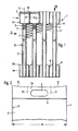
- FIG. 1 to 3 show a heat exchanger (1) which is constructed from a plurality of flat tubes (2) which are placed directly next to one another and with their axes (5) aligned parallel to one another.
- the flat tubes (2) are placed next to one another with widened parts (2a, 2b) provided at the ends and take up heat exchange fins (3) between them, which for better heat dissipation of the in the drawing plane in Fig. 1 on the flat tubes (2nd ) flowing past serve a heat exchange medium, especially air.
- the widened part (2a) or (2b) of the flat tubes (2) is closed in the exemplary embodiment by caps (10) inserted on the end face. These caps are omitted from the lower two tubes of FIG. 3. It can be seen that the middle part (2c) of the flat tubes (2) is considerably narrower than the widened part (2a) and that the flat tubes provided with parallel walls have bends (8) in the area of their longitudinal edges, each of which extends into the parallel walls ( 4) pass over. It can also be seen from the figures that the widened part (2a) or analog (2b) has openings (6, 6 ⁇ ) in the parallel wall parts (4 ⁇ ).
- Fig. 2 shows that the parallel walls (4 ⁇ ) of the expanded part (2a) run approximately in the area between the boundary lines (11) and that from these boundary lines to the outside, where less material is deformed by the ogival shape, also useful End wall parts (12) which run obliquely upwards outwards, while a lower-lying region is present in the region between the boundary lines (11).
- This configuration ensures that even in the middle area, ie. H. in the area of the walls (4 ⁇ ) the material stretch can be kept within the permissible range.
- FIG. 4 to 7 show another embodiment of a flat tube for a refrigerant evaporator, which is also provided with a turbulence insert (70), but is produced in a different way.
- the end regions of a flat tube are not widened, but instead, as the upper part of FIG. 4, a tube (20 ⁇ ) with an oval cross section is selected as the starting material, the walls (40) of which are at a distance (b) from one another.
- This oval tube has the length (B ⁇ ).
- a turbulence insert (70 ⁇ ) in corrugated or zigzag shape is now inserted into an oval tube (20 ⁇ ) designed in this way.
- This turbulence insert (70 ⁇ ) has a total length that is dimensioned such that it corresponds to the length (B) of the deformed part after the deformation of the tube (20 ⁇ ) described below.
- This turbulence insert (70 ⁇ ) with the length (B) is therefore first, as the upper part of FIG. 4 shows, inserted axially into the tube (20), to the extent that it occupies the area (21) (see FIG. 5 and 6), which is then to be deformed. Once this has been done, this central area (21) is pressed together by rolling or pressing, in such a way that in this area the tube (20 ⁇ ) receives the thickness (d) and the Width (B).
- This flat tube (20) designed in this way therefore has widened end regions which do not have the full width (B).
- the turbulence insert (70) over the full length of the width (B), which, due to the deformation process, both assumes its extended position according to FIG. 4 and is secured axially in this position.
- the parts (20a) and (20b) remaining as a result of this deformation process and widened with respect to the region (21) can be provided with openings similar to the openings (6) of the embodiment of FIGS. 1 to 3. In the exemplary embodiment, however, they are each provided with two openings (60) or (60 ⁇ ) which, when they are put together, establish the connection between the individual flat tubes (20).
- outlets (61) projecting outward at the openings (60) are produced, for example, by a suitable stamping process.
- This embodiment then has the advantage that only one type of flat tube (20) is required to build a flat tube evaporator or flat tube heat exchanger, which are soldered to one another.
- the nozzle (61) are dimensioned so that they fit into the openings (60 ⁇ ).
- the open pipe ends are closed by inserted caps (10).
Landscapes
- Engineering & Computer Science (AREA)
- Mechanical Engineering (AREA)
- Physics & Mathematics (AREA)
- Thermal Sciences (AREA)
- General Engineering & Computer Science (AREA)
- Geometry (AREA)
- Heat-Exchange Devices With Radiators And Conduit Assemblies (AREA)
- Compression-Type Refrigeration Machines With Reversible Cycles (AREA)
Priority Applications (1)
| Application Number | Priority Date | Filing Date | Title |
|---|---|---|---|
| AT87109108T ATE43707T1 (de) | 1986-07-09 | 1987-06-24 | Waermetauscher, insbesondere kaeltemittelverdampfer. |
Applications Claiming Priority (2)
| Application Number | Priority Date | Filing Date | Title |
|---|---|---|---|
| DE19863622953 DE3622953A1 (de) | 1986-07-09 | 1986-07-09 | Waermetauscher, insbesondere kaeltemittel-verdampfer |
| DE3622953 | 1986-07-09 |
Publications (2)
| Publication Number | Publication Date |
|---|---|
| EP0253167A1 true EP0253167A1 (fr) | 1988-01-20 |
| EP0253167B1 EP0253167B1 (fr) | 1989-05-31 |
Family
ID=6304670
Family Applications (1)
| Application Number | Title | Priority Date | Filing Date |
|---|---|---|---|
| EP87109108A Expired EP0253167B1 (fr) | 1986-07-09 | 1987-06-24 | Echangeur de chaleur, en particulier évaporateur pour réfrigérant |
Country Status (5)
| Country | Link |
|---|---|
| EP (1) | EP0253167B1 (fr) |
| JP (1) | JPH0739914B2 (fr) |
| AT (1) | ATE43707T1 (fr) |
| DE (2) | DE3622953A1 (fr) |
| ES (1) | ES2008864B3 (fr) |
Cited By (7)
| Publication number | Priority date | Publication date | Assignee | Title |
|---|---|---|---|---|
| DE3900744A1 (de) * | 1989-01-12 | 1990-07-26 | Sueddeutsche Kuehler Behr | Waermetauscher |
| FR2715217A1 (fr) * | 1994-01-20 | 1995-07-21 | Valeo Thermique Moteur Sa | Tube d'échangeur de chaleur, en particulier pour véhicule automobile, procédé pour sa conformation et échangeur de chaleur comprenant de tels tubes. |
| FR2715216A1 (fr) * | 1994-01-20 | 1995-07-21 | Valeo Thermique Moteur Sa | Tube d'échangeur de chaleur, procédé pour sa conformation et échangeur de chaleur comprenant de tels tubes. |
| DE19543986A1 (de) * | 1995-11-25 | 1997-05-28 | Behr Gmbh & Co | Wärmetauscher und ein Verfahren zur Herstellung eines Wärmetauschers |
| DE19722097A1 (de) * | 1997-05-27 | 1998-12-03 | Behr Gmbh & Co | Wärmeübertrager sowie Wärmeübertrageranordnung für ein Kraftfahrzeug |
| EP0874210A3 (fr) * | 1997-04-22 | 1999-11-24 | Whirlpool Corporation | Echangeur de chaleur modulaire, en particulier pour sèche-linge, machines à laver/sécher etc. |
| CN106839854A (zh) * | 2017-01-26 | 2017-06-13 | 上海宝丰机械制造有限公司 | 换热管及包括其的蒸发式冷凝器 |
Families Citing this family (3)
| Publication number | Priority date | Publication date | Assignee | Title |
|---|---|---|---|---|
| JPH0346757U (fr) * | 1989-08-29 | 1991-04-30 | ||
| DE19723878B4 (de) * | 1997-06-06 | 2007-10-25 | Behr Gmbh & Co. Kg | Wärmeübertrager |
| DE10138247A1 (de) * | 2001-08-03 | 2003-02-13 | Behr Gmbh & Co | Wärmetauscheranordnung |
Citations (5)
| Publication number | Priority date | Publication date | Assignee | Title |
|---|---|---|---|---|
| US2345331A (en) * | 1942-04-18 | 1944-03-28 | Morris Motors Ltd | Heat interchange apparatus |
| FR2406794A1 (fr) * | 1977-10-21 | 1979-05-18 | Volkswagenwerk Ag | Echangeur de chaleur, en particulier de metal leger |
| US4269265A (en) * | 1979-11-29 | 1981-05-26 | Modine Manufacturing Company | Tubular heat exchanger with turbulator |
| FR2512940A1 (fr) * | 1981-09-14 | 1983-03-18 | Sueddeutsche Kuehler Behr | Echangeur de chaleur a tubes de profil aplati a elements rapportes generateurs de turbulence |
| FR2576678A1 (fr) * | 1985-01-26 | 1986-08-01 | Sueddeutsche Kuehler Behr | Echangeur de chaleur, en particulier evaporateur pour refrigerant |
-
1986
- 1986-07-09 DE DE19863622953 patent/DE3622953A1/de not_active Withdrawn
-
1987
- 1987-06-10 JP JP62143433A patent/JPH0739914B2/ja not_active Expired - Lifetime
- 1987-06-24 AT AT87109108T patent/ATE43707T1/de not_active IP Right Cessation
- 1987-06-24 ES ES87109108T patent/ES2008864B3/es not_active Expired
- 1987-06-24 EP EP87109108A patent/EP0253167B1/fr not_active Expired
- 1987-06-24 DE DE8787109108T patent/DE3760214D1/de not_active Expired
Patent Citations (5)
| Publication number | Priority date | Publication date | Assignee | Title |
|---|---|---|---|---|
| US2345331A (en) * | 1942-04-18 | 1944-03-28 | Morris Motors Ltd | Heat interchange apparatus |
| FR2406794A1 (fr) * | 1977-10-21 | 1979-05-18 | Volkswagenwerk Ag | Echangeur de chaleur, en particulier de metal leger |
| US4269265A (en) * | 1979-11-29 | 1981-05-26 | Modine Manufacturing Company | Tubular heat exchanger with turbulator |
| FR2512940A1 (fr) * | 1981-09-14 | 1983-03-18 | Sueddeutsche Kuehler Behr | Echangeur de chaleur a tubes de profil aplati a elements rapportes generateurs de turbulence |
| FR2576678A1 (fr) * | 1985-01-26 | 1986-08-01 | Sueddeutsche Kuehler Behr | Echangeur de chaleur, en particulier evaporateur pour refrigerant |
Cited By (15)
| Publication number | Priority date | Publication date | Assignee | Title |
|---|---|---|---|---|
| DE3900744A1 (de) * | 1989-01-12 | 1990-07-26 | Sueddeutsche Kuehler Behr | Waermetauscher |
| FR2715217A1 (fr) * | 1994-01-20 | 1995-07-21 | Valeo Thermique Moteur Sa | Tube d'échangeur de chaleur, en particulier pour véhicule automobile, procédé pour sa conformation et échangeur de chaleur comprenant de tels tubes. |
| FR2715216A1 (fr) * | 1994-01-20 | 1995-07-21 | Valeo Thermique Moteur Sa | Tube d'échangeur de chaleur, procédé pour sa conformation et échangeur de chaleur comprenant de tels tubes. |
| EP0664428A1 (fr) * | 1994-01-20 | 1995-07-26 | Valeo Thermique Moteur | Tube d'échangeur de chaleur, procédé pour sa conformation et échangeur de chaleur comprenant de tels tubes |
| EP0665414A1 (fr) * | 1994-01-20 | 1995-08-02 | Valeo Thermique Moteur | Tube d'échangeur de chaleur, en particulier pour véhicule automobile, procédé pour sa conformation et échangeur de chaleur comprenant de tels tubes |
| US5579832A (en) * | 1994-01-20 | 1996-12-03 | Valeo Thermique Moteur | Heat exchanger tube, apparatus for forming such a tube, and a heat exchanger comprising such tubes |
| DE19543986A1 (de) * | 1995-11-25 | 1997-05-28 | Behr Gmbh & Co | Wärmetauscher und ein Verfahren zur Herstellung eines Wärmetauschers |
| EP0775884A3 (fr) * | 1995-11-25 | 1997-10-29 | Behr Gmbh & Co | Echangeur de chaleur et son procédé de fabrication |
| US6397937B1 (en) | 1995-11-25 | 2002-06-04 | Behr Gmbh & Co. | Heat exchanger and a method for producing a heat exchanger |
| US6899168B2 (en) | 1995-11-25 | 2005-05-31 | Behr Gmbh & Co. | Heat exchanger and a method for producing a heat exchanger |
| US7048040B2 (en) | 1995-11-25 | 2006-05-23 | Behr Gmbh & Co. | Heat exchanger and a method for producing a heat exchanger |
| EP0874210A3 (fr) * | 1997-04-22 | 1999-11-24 | Whirlpool Corporation | Echangeur de chaleur modulaire, en particulier pour sèche-linge, machines à laver/sécher etc. |
| DE19722097A1 (de) * | 1997-05-27 | 1998-12-03 | Behr Gmbh & Co | Wärmeübertrager sowie Wärmeübertrageranordnung für ein Kraftfahrzeug |
| US6012512A (en) * | 1997-05-27 | 2000-01-11 | Behr Gmbh & Co. | Heat exchanger as well as heat exchanger arrangement for a motor vehicle |
| CN106839854A (zh) * | 2017-01-26 | 2017-06-13 | 上海宝丰机械制造有限公司 | 换热管及包括其的蒸发式冷凝器 |
Also Published As
| Publication number | Publication date |
|---|---|
| JPS6317391A (ja) | 1988-01-25 |
| ATE43707T1 (de) | 1989-06-15 |
| JPH0739914B2 (ja) | 1995-05-01 |
| DE3760214D1 (en) | 1989-07-06 |
| EP0253167B1 (fr) | 1989-05-31 |
| DE3622953A1 (de) | 1988-01-21 |
| ES2008864B3 (es) | 1989-08-16 |
Similar Documents
| Publication | Publication Date | Title |
|---|---|---|
| DE60219538T2 (de) | Wärmetauscher | |
| DE3752324T2 (de) | Kondensator | |
| EP0379701B1 (fr) | Echangeur de chaleur | |
| DE3781651T2 (de) | Verfahren zum herstellen einer waermetauschereinheit mit integrierten kuehlrippen. | |
| DE69428219T2 (de) | Plattenwärmetauscher | |
| DE69306065T2 (de) | Wärmetauscher | |
| DE60209994T2 (de) | Wärmetauscherrohr | |
| DE69210452T2 (de) | Wärmetauscher mit Rohrbündel, insbesondere für Kraftfahrzeug | |
| DE4340378C2 (de) | Wärmeaustauscher und Verfahren zur Herstellung derselben | |
| DE2847525C3 (de) | Wärmetauscher für Verdampfer, insbesondere für Klimaanlagen | |
| DE4004949C2 (fr) | ||
| DE69708730T2 (de) | Wärmetauscher und Verfahren zu seiner Herstellung | |
| DE69504631T2 (de) | Verfahren zum hartlöten von flachen rohren für lamellenförmige wärmetauscher | |
| EP0672882A1 (fr) | Ailette pour échangeur de chaleur | |
| DE3303681A1 (de) | Waermeaustauscher | |
| DE19543149C2 (de) | Wärmetauscher, insbesondere Kältemittelverdampfer | |
| DE69203388T2 (de) | Verfahren zur Herstellung eines Rohrbündelwärmetauschers. | |
| DE3502619C2 (fr) | ||
| DE3834822A1 (de) | Waermetauscher | |
| EP0253167B1 (fr) | Echangeur de chaleur, en particulier évaporateur pour réfrigérant | |
| DE3440064C2 (fr) | ||
| DE69406401T2 (de) | Wärmetauscher | |
| DE2113581A1 (de) | Flachrohr und Verfahren zum Herstellen desselben | |
| DE2404630A1 (de) | Waermeaustauscher | |
| DE3028096A1 (de) | Anpassungsverfahren eines metallrohres insbesondere fuer waermetauscher u.dgl. |
Legal Events
| Date | Code | Title | Description |
|---|---|---|---|
| PUAI | Public reference made under article 153(3) epc to a published international application that has entered the european phase |
Free format text: ORIGINAL CODE: 0009012 |
|
| AK | Designated contracting states |
Kind code of ref document: A1 Designated state(s): AT DE ES FR GB IT SE |
|
| 17P | Request for examination filed |
Effective date: 19880205 |
|
| 17Q | First examination report despatched |
Effective date: 19880708 |
|
| GRAA | (expected) grant |
Free format text: ORIGINAL CODE: 0009210 |
|
| AK | Designated contracting states |
Kind code of ref document: B1 Designated state(s): AT DE ES FR GB IT SE |
|
| REF | Corresponds to: |
Ref document number: 43707 Country of ref document: AT Date of ref document: 19890615 Kind code of ref document: T |
|
| ITF | It: translation for a ep patent filed | ||
| GBT | Gb: translation of ep patent filed (gb section 77(6)(a)/1977) | ||
| REF | Corresponds to: |
Ref document number: 3760214 Country of ref document: DE Date of ref document: 19890706 |
|
| ET | Fr: translation filed | ||
| PLBE | No opposition filed within time limit |
Free format text: ORIGINAL CODE: 0009261 |
|
| 26N | No opposition filed | ||
| PGFP | Annual fee paid to national office [announced via postgrant information from national office to epo] |
Ref country code: SE Payment date: 19920519 Year of fee payment: 6 |
|
| PGFP | Annual fee paid to national office [announced via postgrant information from national office to epo] |
Ref country code: AT Payment date: 19920521 Year of fee payment: 6 |
|
| PGFP | Annual fee paid to national office [announced via postgrant information from national office to epo] |
Ref country code: ES Payment date: 19920525 Year of fee payment: 6 |
|
| ITTA | It: last paid annual fee | ||
| PG25 | Lapsed in a contracting state [announced via postgrant information from national office to epo] |
Ref country code: AT Effective date: 19930624 |
|
| PG25 | Lapsed in a contracting state [announced via postgrant information from national office to epo] |
Ref country code: SE Effective date: 19930625 Ref country code: ES Free format text: LAPSE BECAUSE OF EXPIRATION OF PROTECTION Effective date: 19930625 |
|
| EUG | Se: european patent has lapsed |
Ref document number: 87109108.8 Effective date: 19940110 |
|
| PGFP | Annual fee paid to national office [announced via postgrant information from national office to epo] |
Ref country code: GB Payment date: 19980526 Year of fee payment: 12 |
|
| PGFP | Annual fee paid to national office [announced via postgrant information from national office to epo] |
Ref country code: DE Payment date: 19980620 Year of fee payment: 12 |
|
| PGFP | Annual fee paid to national office [announced via postgrant information from national office to epo] |
Ref country code: FR Payment date: 19980622 Year of fee payment: 12 |
|
| PG25 | Lapsed in a contracting state [announced via postgrant information from national office to epo] |
Ref country code: GB Free format text: LAPSE BECAUSE OF NON-PAYMENT OF DUE FEES Effective date: 19990624 |
|
| PG25 | Lapsed in a contracting state [announced via postgrant information from national office to epo] |
Ref country code: FR Free format text: THE PATENT HAS BEEN ANNULLED BY A DECISION OF A NATIONAL AUTHORITY Effective date: 19990630 |
|
| REG | Reference to a national code |
Ref country code: ES Ref legal event code: FD2A Effective date: 19990601 |
|
| GBPC | Gb: european patent ceased through non-payment of renewal fee |
Effective date: 19990624 |
|
| PG25 | Lapsed in a contracting state [announced via postgrant information from national office to epo] |
Ref country code: DE Free format text: LAPSE BECAUSE OF NON-PAYMENT OF DUE FEES Effective date: 20000503 |
|
| REG | Reference to a national code |
Ref country code: FR Ref legal event code: ST |
|
| PG25 | Lapsed in a contracting state [announced via postgrant information from national office to epo] |
Ref country code: IT Free format text: LAPSE BECAUSE OF NON-PAYMENT OF DUE FEES;WARNING: LAPSES OF ITALIAN PATENTS WITH EFFECTIVE DATE BEFORE 2007 MAY HAVE OCCURRED AT ANY TIME BEFORE 2007. THE CORRECT EFFECTIVE DATE MAY BE DIFFERENT FROM THE ONE RECORDED. Effective date: 20050624 |