EP0253206A2 - Einrichtung zum Flüssigkeitskühlen von Zentraleinheiten - Google Patents
Einrichtung zum Flüssigkeitskühlen von Zentraleinheiten Download PDFInfo
- Publication number
- EP0253206A2 EP0253206A2 EP87109467A EP87109467A EP0253206A2 EP 0253206 A2 EP0253206 A2 EP 0253206A2 EP 87109467 A EP87109467 A EP 87109467A EP 87109467 A EP87109467 A EP 87109467A EP 0253206 A2 EP0253206 A2 EP 0253206A2
- Authority
- EP
- European Patent Office
- Prior art keywords
- coolant
- cooling
- units
- liquid cooling
- unit
- Prior art date
- Legal status (The legal status is an assumption and is not a legal conclusion. Google has not performed a legal analysis and makes no representation as to the accuracy of the status listed.)
- Withdrawn
Links
Images
Classifications
-
- H—ELECTRICITY
- H05—ELECTRIC TECHNIQUES NOT OTHERWISE PROVIDED FOR
- H05K—PRINTED CIRCUITS; CASINGS OR CONSTRUCTIONAL DETAILS OF ELECTRIC APPARATUS; MANUFACTURE OF ASSEMBLAGES OF ELECTRICAL COMPONENTS
- H05K7/00—Constructional details common to different types of electric apparatus
- H05K7/20—Modifications to facilitate cooling, ventilating, or heating
- H05K7/20536—Modifications to facilitate cooling, ventilating, or heating for racks or cabinets of standardised dimensions, e.g. electronic racks for aircraft or telecommunication equipment
- H05K7/20627—Liquid coolant without phase change
- H05K7/20654—Liquid coolant without phase change within rooms for removing heat from cabinets
Definitions
- the invention relates to a device for liquid cooling of central processing units in data technology.
- cooling circuits are used to dissipate the heat loss. Water can be used.
- the cooling unit In order to achieve a high level of reliability for complete systems of the central unit and cooling unit, the cooling unit must be designed redundantly.
- the object of the present invention is to design the device for liquid cooling of central units such that if one of the redundant cooling units fails, the failed redundant cooling unit can be complimented quickly.
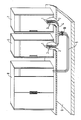
- the device is designed according to the invention such that two redundant cooling units are provided, each of which is housed in its own cabinet 6, 7 and which are connected to one another via a coolant line 4 and a further coolant line 5 to the associated central unit 8 are that between the coolant inflow and outflow of the respective cooling unit and the two connected coolant line 4, a separation point 3 is provided, in front of and behind which a coolant shut-off valve 1, 2 is arranged.
- the central unit of a data system is accommodated in the cabinet 8.
- Two redundantly connected cooling units are used for cooling, but they are accommodated separately in two different cabinets 6, 7. Both cooling units are connected to one another via a coolant line 4 and a further coolant line 5 leads from this common line 4 to the central unit 8.
- the two cooling units are connected to the common coolant line 4 via an easily detachable separation point 3.
- a coolant shut-off valve 1, 2 is also provided before and after each separation point.
- Another coolant shut-off valve is then in each case between this coolant line 4 and the coolant line 5, a separation point is also provided, which is followed by a coolant shut-off valve 10.
- the coolant lines are laid in a raised floor 9, which is located below the central unit and the cooling units.
- the system automatically switches to the second unit.
- On the fancy Cooling unit then shut off the coolant taps 1 and 2 and loosen the screw connection.
- the central unit continues to work with the cooling unit ready for operation.
- the defective unit can be removed and replaced with a functional one. After connecting and opening the closed taps, a mutual switchover between the two operational cooling units can be resumed due to an even distribution of the operating times. The defective cooling unit can then be repaired regardless of the operation.
- the invention relates to a device for liquid cooling of central units in data technology, redundant cooling units are used. If one of the redundant cooling units becomes defective, the redundancy of the cooling system should be restored as quickly as possible.
- the invention here provides two redundant cooling units, each of which is accommodated in a separate cabinet 6, 7 and which are connected to one another via a common coolant line 4 and a further coolant line 5 to the associated central unit 8.
- a separation point 3 is provided between the coolant inflow and outflow of the respective cooling unit and the coolant line 4 connecting the two, in front of and behind which a coolant shut-off valve 1, 2 is arranged.
Landscapes
- Engineering & Computer Science (AREA)
- Aviation & Aerospace Engineering (AREA)
- Physics & Mathematics (AREA)
- Thermal Sciences (AREA)
- Microelectronics & Electronic Packaging (AREA)
- Cooling Or The Like Of Electrical Apparatus (AREA)
Abstract
Description
- Die Erfindung betrifft eine Einrichtung zum Flüssigkeitskühlen von Zentraleinheiten der Datentechnik.
- Für die Kühlung hochintegrierter elektronischer Baugruppen in Datenverarbeitungsanlagen werden zur Abführung der Verlustleistungswärme Kühlkreisläufe eingesetzt, wobei als Kühlmittel z.B. Wasser verwendet werden kann. Um eine hohe Zuverlässigkeit kompletter Systeme von Zentraleinheit und Kühlaggregat zu erreichen ist es erforderlich, das Kühlaggregat redundant auszuführen.
- Aufgabe der vorliegenden Erfindung ist es, die Einrichtung zum Flüssigkeitskühlen von Zentraleinheiten derart auszugestalten, daß bei Ausfall eines der redundanten Kühlaggregate eine rasche Komplimentierung des ausgefallenen redundanten Kühlaggregats möglich ist.
- Zur Lösung dieser Aufgabe wird gemäß der Erfindung die Einrichtung derart ausgebildet, daß zwei redundante Kühlaggregate vorgesehen sind, von denen jedes in einem eigenen Schrank 6, 7 untergebracht ist und die über eine Kühlmittelleitung 4 miteinander und eine weitere Kühlmittelleitung 5 mit der zugehörigen Zentraleinheit 8 verbunden sind, daß zwischen Kühlmittelzu- bzw. Abfluß des jeweiligen Kühlaggregates und der beiden verbindunden Kühlmittelleitung 4 eine Trennstelle 3 vorgesehen ist, vor und hinter der jeweils ein Kühlmittelabsperrhahn 1, 2 angeordnet ist.
- Außerdem ist es vorteilhaft, daß unterhalb der Schränke 6, 6, 8 ein Doppelboden 9 vorgesehen ist, indem die Kühlmittelleitungen 4, 5 verlegt sind.
- Durch diese Maßnahmen ist gewährleistet, daß das defekte Kühlaggregat in kurzer Zeit von der Kühlmittelleitung getrennt und durch ein intaktes Gerät ersetzt werden kann, sodaß die allenfalls anfallende Reperatur nicht sofort und an Ort und Stelle sondern ohne Zeitdruck an jedem beliebigen Ort z.B. am Fertigungsort durchgeführt werden kann.
- Anhand des Ausführungsbeispiels nach der FIG wird die Erfindung näher erläutert. Im Schrank 8 ist die Zentraleinheit eines Datensystems untergebracht. Zur Kühlung werden zwei redundant geschaltete Kühlaggregate verwendet, die jedoch getrennt in zwei unterschiedlichen Schränken 6, 7 untergebracht sind. Beide Kühlaggregate sind über eine Kühlmittelleitung 4 miteinander verbunden und eine weitere Kühlmittelleitung 5 führt von dieser gemeinsamen Leitung 4 zur Zentraleinheit 8. Die beiden Kühlaggregate sind mit der gemeinsamen Kühlmittelleitung 4 über eine leicht lösbare Trennstelle 3 verbunden. Vor und nach jeder Trennstelle ist zudem ein Kühlmittelabsperrhahn 1, 2 vorgesehen. Ein weiterer Kühlmittelabsperrhahn liegt dann jeweils zwischen dieser Kühlmittelleitung 4 und der Kühlmittelleitung 5 ist ebenfalls eine Trennstelle vorgesehen, der jeweils ein Kühlmittelabsperrhahn 10 nachgeordnet ist.
- Die Kühlmittelleitungen sind in einem Doppelboden 9, der sich unterhalb der Zentraleinheit und der Kühlaggregate befindet verlegt.
- Bei Ausfall eines der Kühlaggregate wird automatisch auf das zweite Aggregat umgeschaltet. An dem ausgefallenen Kühlaggregat werden dann die Kühlmittelhähne 1 und 2 abgesperrt und die Verschraubung gelöst. Die Zentraleinheit arbeitet mit dem betriebsbereiten Kühlaggregat weiter. Das defekte Aggregat kann entfernt und durch ein funktionsfähiges ersetzt werden. Nach Anschluß und Öffnen der geschlossenen Hähne kann aufgrund einer Gleichverteilung der Betriebszeiten eine wechselseitige Umschaltung zwischen den beiden betriebsbereiten Kühlaggregaten wieder aufgenommen werden. Das defekte Kühlaggregat kann dann unabhängig vom Betrieb repariert werden.
- Die Erfindung bezieht sich auf eine Einrichtung zum Flüssigkeitskühlen von Zentraleinheiten der Datentechnik, dabei werden redundante Kühlaggregate verwendet. Wird eines der redundanten Kühlaggregate defekt, soll das Kühlsystem möglichst rasch in seiner Redundanz wieder hergestellt werden. Die Erfindung sieht hierführ zwei redundante Kühlaggregate vor, von denen jedes in einem eigenen Schrank 6, 7 untergebracht ist und die über eine gemeinsame Kühlmittelleitung 4 miteinander und eine weitere Kühlmittelleitung 5 mit dazugehörigen Zentraleinheit 8 verbunden sind. Zwischen Kühlmittelzu- bzw. Abfluß des jeweiligen Kühlaggregates und der beide verbindenden Kühlmittelleitung 4 ist eine Trennstelle 3 vorgesehen, vor und hinter der jeweils ein Kühlmittelabsperrhahn 1, 2 angeordnet ist.
-
- 1 = Kühlmittelabsperrhahn
- 2 = Kühlmittelabsperrhahn
- 3 = Trennstelle
- 4 = Kühlmittelleitung
- 5 = Kühlmittelleitung
- 6 = Schrank
- 7 = Schrank
- 8 = Zentraleinheit
- 9 = Doppelboden
Claims (2)
dadurch gekennzeichnet, daß zwei redundante Kühlaggregate vorgesehen sind, von denen jedes in einem eigenen Schrank (6, 7) untergebracht ist und die über eine Kühlmittelleitung (4) miteinander und eine weitere Kühlmittelleitung (5) mit der zugehörigen Zentraleinheit (8) verbunden sind, daß zwischen Kühlmittelzu- bzw. Abfluß des jeweiligen Kühlaggregates und der beiden verbindenden Kühlmittelleitung (4) eine Trennstelle (3) vorgesehen ist, vor und hinter der jeweils ein Kühlmittelabsperrhahn (1, 2) angeordnet ist.
dadurch gekennzeichnet, daß unterhalb der Schränke (6, 7, 8) ein Doppelboden (9) vorgesehen ist, indem die Kühlmittelleitungen (4, 5) verlegt sind.
Applications Claiming Priority (2)
| Application Number | Priority Date | Filing Date | Title |
|---|---|---|---|
| DE3622386 | 1986-07-03 | ||
| DE3622386 | 1986-07-03 |
Publications (2)
| Publication Number | Publication Date |
|---|---|
| EP0253206A2 true EP0253206A2 (de) | 1988-01-20 |
| EP0253206A3 EP0253206A3 (de) | 1989-01-18 |
Family
ID=6304328
Family Applications (1)
| Application Number | Title | Priority Date | Filing Date |
|---|---|---|---|
| EP87109467A Withdrawn EP0253206A3 (de) | 1986-07-03 | 1987-07-01 | Einrichtung zum Flüssigkeitskühlen von Zentraleinheiten |
Country Status (1)
| Country | Link |
|---|---|
| EP (1) | EP0253206A3 (de) |
Cited By (1)
| Publication number | Priority date | Publication date | Assignee | Title |
|---|---|---|---|---|
| US8132614B2 (en) | 2005-05-09 | 2012-03-13 | Vacon Oyi | Arrangement for the cooling of liquid-cooled electrical equipment |
Family Cites Families (2)
| Publication number | Priority date | Publication date | Assignee | Title |
|---|---|---|---|---|
| US4016357A (en) * | 1975-07-18 | 1977-04-05 | Burroughs Corporation | Floor structure for the environment of a modular computer system |
| DE3100716A1 (de) * | 1981-01-13 | 1982-08-12 | Günter Dr.-Ing. 5000 Köln Klein | Notkuehlsystem fuer kernreaktoren |
-
1987
- 1987-07-01 EP EP87109467A patent/EP0253206A3/de not_active Withdrawn
Cited By (1)
| Publication number | Priority date | Publication date | Assignee | Title |
|---|---|---|---|---|
| US8132614B2 (en) | 2005-05-09 | 2012-03-13 | Vacon Oyi | Arrangement for the cooling of liquid-cooled electrical equipment |
Also Published As
| Publication number | Publication date |
|---|---|
| EP0253206A3 (de) | 1989-01-18 |
Similar Documents
| Publication | Publication Date | Title |
|---|---|---|
| DE3003291C2 (de) | Zweikanalige Datenverarbeitungsanordnung für Eisenbahnsicherungszwecke | |
| EP0609688A2 (de) | Medizinisches Aggregat oder Gerät für Operationssäle, insbesondere Herz-Lungen-Maschine | |
| DE2040326A1 (de) | Geraet zum automatischen Pruefen elektronischer Stromkreise | |
| EP0951981A2 (de) | Mehrkreistemperiersystem | |
| WO1999056375A2 (de) | Verfahren und anordnung zum bewerkstelligen eines unterbrechungsfreien stromversorgungsbetriebs einer systemeinheit | |
| DE10148470A1 (de) | Vorrichtung und Verfahren zum elektrischen und mechanischen Verbinden von Komponenten eines Automatisierungssystems | |
| EP0253206A2 (de) | Einrichtung zum Flüssigkeitskühlen von Zentraleinheiten | |
| DE8617820U1 (de) | Einrichtung zum Flüssigkeitskühlen von Zentraleinheiten | |
| DE1965314A1 (de) | Datenverarbeitungsanordnung mit zwei Datenverarbeitungsanlagen,insbesondere fuer dieAbwicklung von Vermittlungsvorgaengen in einer Fernsprechvermittlung | |
| DE10311284A1 (de) | Druckmaschine mit zumindest zwei Druckwerke | |
| DE2812362B2 (de) | Befestigungseinrichtung für Leiterplatten | |
| EP0205101B1 (de) | Verfahren zum Betrieb einer Datenverarbeitungsanlage | |
| DE9421001U1 (de) | Anschlußeinheit zur elektrischen Kopplung redundanter Baugruppen mit externer Kommunikationsschnittstelle | |
| EP1196829B1 (de) | Baustein zur steuerung eines antriebs | |
| DE3933343C2 (de) | Operationsmikroskop | |
| DE102020000714A1 (de) | System | |
| DE3239434C1 (de) | Einrichtung zum Überwachen der Funktionsfähigkeit eines Mehr-Rechnersystems | |
| DE202011106406U1 (de) | Dokumentationsvorrichtung für einen Schaltschrank | |
| DE1954910C3 (de) | Anordnung zur Anzeige eines Defekts von Entkopplungsdioden in einer Matrix | |
| EP0090162A2 (de) | Zweikanaliges Fail-Safe-Mikrocomputerschaltwerk, insbesondere für Eisenbahnsicherungsanlagen | |
| DE2652036C3 (de) | Schaltungsanordnung für Verbindungssätze in Fernmelde-, insbesondere Fernsprechvermittlungsanlagen | |
| DE3511208A1 (de) | Schaltungsanordnung zur versorgung eines in einem regelkreis angeordneten stellglieds mit stellsignalen aus einem ersten oder zweiten regler | |
| DE1465953C (de) | Verfahren zum Abschalten einzelner Anlageteile aus einem Steuer und/oder Verriegelungssystem einer aus mehreren Teilen bestehenden Gesamtanlage | |
| DE1613888C (de) | Umformerwerk für Gleichstromübertragung | |
| DE4019673A1 (de) | Schaltmodul fuer paare von an mindestens einen kommunikationsbus angeschlossenen homologen prozessoren |
Legal Events
| Date | Code | Title | Description |
|---|---|---|---|
| PUAI | Public reference made under article 153(3) epc to a published international application that has entered the european phase |
Free format text: ORIGINAL CODE: 0009012 |
|
| AK | Designated contracting states |
Kind code of ref document: A2 Designated state(s): AT BE CH DE FR GB IT LI NL |
|
| PUAL | Search report despatched |
Free format text: ORIGINAL CODE: 0009013 |
|
| AK | Designated contracting states |
Kind code of ref document: A3 Designated state(s): AT BE CH DE FR GB IT LI NL |
|
| STAA | Information on the status of an ep patent application or granted ep patent |
Free format text: STATUS: THE APPLICATION IS DEEMED TO BE WITHDRAWN |
|
| 18D | Application deemed to be withdrawn |
Effective date: 19890719 |
|
| RIN1 | Information on inventor provided before grant (corrected) |
Inventor name: SCHMALZL, DIETER Inventor name: PEITZ, ELMAR, DIPL.-ING. Inventor name: MATERLIK, PETER, DIPL.-ING. |