EP0253234B1 - Vorstellvorrichtung für Leitschaufeln von Turbotriebwerken - Google Patents
Vorstellvorrichtung für Leitschaufeln von Turbotriebwerken Download PDFInfo
- Publication number
- EP0253234B1 EP0253234B1 EP87109592A EP87109592A EP0253234B1 EP 0253234 B1 EP0253234 B1 EP 0253234B1 EP 87109592 A EP87109592 A EP 87109592A EP 87109592 A EP87109592 A EP 87109592A EP 0253234 B1 EP0253234 B1 EP 0253234B1
- Authority
- EP
- European Patent Office
- Prior art keywords
- ring
- turbine housing
- adjustment device
- connecting brackets
- adjustment
- Prior art date
- Legal status (The legal status is an assumption and is not a legal conclusion. Google has not performed a legal analysis and makes no representation as to the accuracy of the status listed.)
- Expired
Links
Images

Classifications
-
- F—MECHANICAL ENGINEERING; LIGHTING; HEATING; WEAPONS; BLASTING
- F01—MACHINES OR ENGINES IN GENERAL; ENGINE PLANTS IN GENERAL; STEAM ENGINES
- F01D—NON-POSITIVE DISPLACEMENT MACHINES OR ENGINES, e.g. STEAM TURBINES
- F01D17/00—Regulating or controlling by varying flow
- F01D17/10—Final actuators
- F01D17/12—Final actuators arranged in stator parts
- F01D17/14—Final actuators arranged in stator parts varying effective cross-sectional area of nozzles or guide conduits
- F01D17/16—Final actuators arranged in stator parts varying effective cross-sectional area of nozzles or guide conduits by means of nozzle vanes
- F01D17/162—Final actuators arranged in stator parts varying effective cross-sectional area of nozzles or guide conduits by means of nozzle vanes for axial flow, i.e. the vanes turning around axes which are essentially perpendicular to the rotor centre line
Definitions
- the invention relates to an adjusting device for pivotable guide vanes of turbo engines with an adjustment ring located outside the turbine housing, which is rotatably supported by bearings on a coaxial carrier ring and on which the pivoting lever of the guide vanes is arranged so as to be movable on the blade side perpendicular to the pivoting plane, and the carrier ring is heat-insulating over several Scope distributed connecting tabs is connected to the turbine housing.
- the object of the invention is to avoid these disadvantages and to ensure an exact adjustment of the guide vanes regardless of the temperature fluctuations caused by different operating states, whereby a structurally simple device should be created which at the same time has high rigidity and works equally reliably under all temperature conditions.
- the object is achieved in that the connecting straps are flat sections of a ring band.
- This arrangement ensures that the heat flow from the turbine housing to the carrier and adjusting ring remains relatively low, regardless of the operating state of the engine, and that this maintains an approximately constant temperature. Since the turbine housing is generally surrounded by a cooling air flow, the heat conduction via the connecting straps is further restricted. Small thermal expansions in the axial direction of the engine can be absorbed by the tabs without errors for the blade adjustment, while the coaxiality of the carrier ring and the engine is guaranteed.
- the connecting straps are flat sections of a ring band, a surface / cross-sectional ratio which is favorable for reduced heat conduction can be achieved.
- the connecting straps have a certain elasticity in the radial direction, as a result of which the different thermal expansions of the turbine housing, which becomes hot during operation, and of the adjustment and carrier ring that remain cool are compensated for.
- the connecting straps are connected to a fastening ring fastened to the turbine housing. This enables simple and exact assembly of the adjusting device to be achieved.
- the carrier ring, fastening ring and connecting lugs are combined to form a bearing ring which is designed as an integral component, which leads to a simplification of the production.
- the bearing ring can consist of two or more ring segments connected to one another, whereby the fastening of the adjusting device is facilitated.
- a fastening ring 2 is screwed to the turbine housing 9. This is connected to the U-shaped carrier ring 7 via flat connecting straps 8 (FIG. 2).
- the adjusting ring 4 is rotatably supported in the circumferential direction by means of guide rollers 5 distributed uniformly over the circumference, which are mounted by bolts 6 in the carrier ring 7, its precise guidance being ensured by the shoulders 11 of the adjusting ring 4.
- the adjusting ring 4 is provided with axial bores 10, in which the spherical ends of the pivot levers 3 are guided. On the blade side, the pivot levers 3 are firmly connected to the pivotable guide vanes 1.
- the adjusting ring 4 is rotated in the circumferential direction by a device (not shown), as a result of which the spherical ends of the pivot levers 3 located in the bores 10 are also moved and in this way pivot the guide vanes 1.
- the pivot levers 3 are bent elastically.
- the connecting straps 8 and the swivel levers 3 are designed as flat tongues, as a result of which the heat flow from the hot turbine housing 9 onto the adjusting device remains low.
Landscapes
- Engineering & Computer Science (AREA)
- Mechanical Engineering (AREA)
- General Engineering & Computer Science (AREA)
- Control Of Turbines (AREA)
- Turbine Rotor Nozzle Sealing (AREA)
- Supercharger (AREA)
- Support Of The Bearing (AREA)
Description
- Die Erfindung betrifft eine Verstellvorrichtung für schwenkbare Leitschaufeln von Turbotriebwerken mit einem außerhalb des Turbinengehäuses befindlichen Verstellring, der über Lager an einem koaxialen Trägerring drehbar gelagert ist und an dem schaufelseitig senkrecht zur Schwenkebene biegsame Schwenkhebel der Leitschaufeln beweglich angeordnet sind, und der Trägerring wärmedämmend über mehrere am Umfang verteilte Verbindungslaschen mit dem Turbinengehäuse verbunden ist.
- Eine derartige Verstellvorrichtung aus der US-PS 4 035 101 bekanntgeworden, bei der ein Verstellring koaxial neben einem stationären Ring angeordnet ist, wobei der stationäre Ring über eine Vielzahl von Verbindungslaschen beweglich am Gehäuse befestigt ist. Der Verstellring ist mittels Rollen, die an den Laschen angebracht sind, in Umfangsrichtung verdrehbar gelagert. Diese Anordnung benötigt eine Vielzahl von Scharnieren und Lagern, welche im Betrieb hohen Temperaturschwankungen ausgesetzt sind. Dadurch ist bei niedrigen Temperaturen ein Lagerspiel, bzw. bei hohen Temperaturen ein Klemmen bzw. ein Verspannen einzelner Glieder möglich.
- Eine weitere Verstellvorrichtung ist aus der US-PS 2 933 234 bekannt. Hierbei ist ein Verstellring über Gleitglieder an konzentrisch innen liegenden Trägerringsegmenten gelagert, welche wiederum am Gehäuse des Turbotriebwerkes befestigt sind. Die biegsamen Schwenkhebel der Leitschaufeln sind über Kugelgelenke im Verstellring gelagert. Diese Anordnung hat zur Folge, daß sich die Triebwerkswärme ungehindert auf die Verstellvorrichtung übertragen kann, wodurch sich große Temperaturunterschiede zwischen der Start- und Betriebsphase des Triebwerkes mit entsprechend hohen Wärmedehnungen der Verstellvorrichtung ergeben. Um diese aufnehmen zu können, müssen ausreichende Elastizitäten oder Spiele in der Verstellvorrichtung vorgesehen sein. Dies wiederum führt wegen den großen zu übertragenden Betätigungskräften zu Ungenauigkeiten der Leitschaufelverstellungen, welche mit Wirkungsgradverlusten verbunden sind. Es kann z.B. durch Vibrationen sogar zu mechanischen Schäden führen.
- Aufgabe der Erfindung ist es, diese Nachteile zu vermeiden und eine exakte Einstellung der Leitschaufeln unabhängig von den durch unterschiedliche Betriebszustände hervorgerufenen Temperaturschwankungen zu gewährleisten, wobei eine konstruktiv möglichst einfache Vorrichtung geschaffen werden soll, die gleichzeitig hohe Steifigkeit aufweist und unter allen Temperaturbedingungen gleich zuverlässig funktioniert.
- Erfindungsgemäß wird die Aufgabe dadurch gelöst, daß die Verbindungslaschen flache Abschnitte eines Ringbandes sind.
- Durch diese Anordnung wird erreicht, daß der Wärmefluß vom Turbinengehäuse auf Träger- und Verstellring unabhängig vom Betriebszustand des Triebwerkes relativ gering bleibt und dieser eine in etwa konstante Temperatur beibehält. Da das Turbinengehäuse im allgemeinen von einem Kühlluftstrom umgeben ist, wird die Wärmeleitung über die Verbindungslaschen weiter eingeschränkt. Geringe Wärmedehnungen in triebwerksaxialer Richtung können ohne Fehler für die Schaufeleinstellung von den Laschen aufgenommen werden, während die Koaxialität von Trägerring und Triebwerk gewährleistet bleibt.
- Dadurch daß die Verbindungslaschen flache Abschnitte eines Ringbandes sind, läßt sich ein für reduzierte Wärmeleitung günstiges Oberflächen-/ Querschnittsverhältnis erzielen. Außerdem weisen die Verbindungslaschen in radialer Richtung eine gewisse Elastizität auf, wodurch die unterschiedlichen Wärmedehnungen des im Betrieb heiß werdenden Turbinengehäuses und des kühl bleibenden Verstell- und Trägerrings ausgeglichen wird.
- In einer besonderen Ausführungsform sind die Verbindungslaschen mit einem am Turbinengehäuse befestigten Befestigungsring verbunden. Dadurch läßt sich eine einfache und exakte Montage der Verstellvorrichtung erzielen.
- In einer weiteren Ausführungsform sind Trägerring, Befestigungsring und Verbindungslaschen zu einem Lagerring zusammengefaßt, der als ein integrales Bauteil ausgeführt ist, welches zu einer Vereinfachung der Herstellung führt.
- Der Lagerring kann in einer weiteren Ausführungsform aus zwei oder mehreren miteinander verbundenen Ringsegmenten bestehen, wodurch die Befestigung der Verstellvorrichtung erleichtert wird.
- Anhand der Zeichnungen wird ein Ausführungsbeispiel weiter beschrieben. Dabei zeigt:
- Fig. 1 einen Längsschnitt durch einen Leitschaufelkranz,
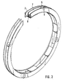
- Fig. 2 ein Schrägbild des Träger- und Befestigungsringes.
- Nach Fig. 1 ist ein Befestigungsring 2 am Turbinengehäuse 9 verschraubt. Über flache Verbindungslaschen 8 ist dieser mit dem U-förmigen Trägerring 7 verbunden (Fig. 2). Über gleichmäßig über dem Umfang verteilte Führungsrollen 5, die durch Bolzen 6 im Trägerring 7 montiert sind, ist der Verstellring 4 in Umfangsrichtung drehbar gelagert, wobei dessen genaue Führung durch die Schultern 11 des Verstellringes 4 gewährleistet wird. Der Verstellring 4 ist mit axialen Bohrungen 10 versehen, in denen die kugelförmigen Enden der Schwenkhebel 3 geführt werden. Schaufelseitig sind die Schwenkhebel 3 fest mit den schwenkbaren Leitschaufeln 1 verbunden.- Zur Verstellung der Leitschaufeln 1 wird der Verstellring 4 durch eine nicht dargestellte Vorrichtung in Umfangsrichtung verdreht, wodurch die in den Bohrungen 10 befindlichen kugelförmigen Enden der Schwenkhebel 3 mitbewegt werden und auf diese Weise die Leitschaufeln 1 schwenken. Dabei werden die Schwenkhebel 3 elastisch verbogen.
- Die Verbindungslaschen 8 und die Schwenkhebel 3 sind als flache Zungen ausgeführt, wodurch der Wärmefluß vom heißen Turbinengehäuse 9 auf die Verstellvorrichtung gering bleibt.
Claims (4)
Priority Applications (1)
| Application Number | Priority Date | Filing Date | Title |
|---|---|---|---|
| AT87109592T ATE47617T1 (de) | 1986-07-09 | 1987-07-03 | Vorstellvorrichtung fuer leitschaufeln von turbotriebwerken. |
Applications Claiming Priority (2)
| Application Number | Priority Date | Filing Date | Title |
|---|---|---|---|
| DE3623001 | 1986-07-09 | ||
| DE3623001A DE3623001C1 (de) | 1986-07-09 | 1986-07-09 | Verstellvorrichtung fuer schwenkbare Leitschaufeln von Turbotriebwerken |
Publications (2)
| Publication Number | Publication Date |
|---|---|
| EP0253234A1 EP0253234A1 (de) | 1988-01-20 |
| EP0253234B1 true EP0253234B1 (de) | 1989-10-25 |
Family
ID=6304703
Family Applications (1)
| Application Number | Title | Priority Date | Filing Date |
|---|---|---|---|
| EP87109592A Expired EP0253234B1 (de) | 1986-07-09 | 1987-07-03 | Vorstellvorrichtung für Leitschaufeln von Turbotriebwerken |
Country Status (5)
| Country | Link |
|---|---|
| US (1) | US4810165A (de) |
| EP (1) | EP0253234B1 (de) |
| JP (1) | JPH0735734B2 (de) |
| AT (1) | ATE47617T1 (de) |
| DE (2) | DE3623001C1 (de) |
Families Citing this family (16)
| Publication number | Priority date | Publication date | Assignee | Title |
|---|---|---|---|---|
| GB2206381B (en) * | 1987-06-30 | 1991-10-09 | Rolls Royce Plc | A variable stator vane arrangement for a compressor |
| US5049033A (en) * | 1990-02-20 | 1991-09-17 | General Electric Company | Blade tip clearance control apparatus using cam-actuated shroud segment positioning mechanism |
| DE4102188C2 (de) * | 1991-01-25 | 1994-09-22 | Mtu Muenchen Gmbh | Leitschaufel-Verstelleinrichtung einer Turbine eines Gasturbinentriebwerks |
| EP0532907B1 (de) * | 1991-09-19 | 1996-02-21 | Asea Brown Boveri Ag | Axialdurchströmte Turbine |
| DE4213709A1 (de) * | 1992-04-25 | 1993-10-28 | Asea Brown Boveri | Axialdurchströmte Turbine |
| GB2301867A (en) * | 1995-06-05 | 1996-12-18 | Rolls Royce Plc | Supporting unison rings in pivotable vane actuating mechanisms |
| US6174129B1 (en) | 1999-01-07 | 2001-01-16 | Siemens Westinghouse Power Corporation | Turbine vane clocking mechanism and method of assembling a turbine having such a mechanism |
| DE10013335A1 (de) | 2000-03-17 | 2001-09-20 | Abb Turbo Systems Ag Baden | Leitapparat für eine axial durchströmte Abgasturbine |
| SE519353C2 (sv) * | 2000-11-15 | 2003-02-18 | Volvo Aero Corp | Stator till en gasturbin |
| WO2004053299A1 (en) * | 2003-05-06 | 2004-06-24 | Honeywell International Inc. | Tamperproof and calibration device, especially for a turbocharger with a variable nozzle device |
| DE10351202A1 (de) * | 2003-11-03 | 2005-06-02 | Mtu Aero Engines Gmbh | Vorrichtung zum Verstellen von Leitschaufeln |
| FR2902454A1 (fr) * | 2006-06-16 | 2007-12-21 | Snecma Sa | Stator de turbomachine comportant un etage d'aubes de redresseurs actionnees par une couronne rotative a centrage automatique |
| US9039355B2 (en) | 2012-05-31 | 2015-05-26 | United Technologies Corporation | Actuator mounted to torque box |
| CN104533540B (zh) * | 2014-11-14 | 2016-04-20 | 沈阳黎明航空发动机(集团)有限责任公司 | 一种保证作动环与压气机机匣同心度的装置 |
| FR3063779B1 (fr) * | 2017-03-07 | 2022-11-04 | Safran Aircraft Engines | Anneau de commande de calage d'un etage d'aube d'un stator |
| US12467383B2 (en) | 2024-03-07 | 2025-11-11 | Pratt & Whitney Canada Corp. | Joint for connection to variable guide vane of gas turbine engine |
Family Cites Families (21)
| Publication number | Priority date | Publication date | Assignee | Title |
|---|---|---|---|---|
| US2637984A (en) * | 1950-07-26 | 1953-05-12 | Gen Electric | Turbine |
| BE514728A (de) * | 1951-10-10 | |||
| GB755527A (en) * | 1953-10-15 | 1956-08-22 | Power Jets Res & Dev Ltd | Mounting of swivelling guide vane elements in axial flow elastic fluid turbines |
| US2778564A (en) * | 1953-12-01 | 1957-01-22 | Havilland Engine Co Ltd | Stator blade ring assemblies for axial flow compressors and the like |
| US2933234A (en) * | 1954-12-28 | 1960-04-19 | Gen Electric | Compressor stator assembly |
| US2932440A (en) * | 1955-05-20 | 1960-04-12 | Gen Electric | Compressor blade adjustment means |
| DE1108988B (de) * | 1957-04-04 | 1961-06-15 | Napier & Son Ltd | Verstellbarer Leitschaufelkranz fuer Turbinen, insbesondere Gasturbinen |
| US2936108A (en) * | 1957-04-29 | 1960-05-10 | Gen Electric | Compressor |
| US3303992A (en) * | 1965-03-03 | 1967-02-14 | Gen Motors Corp | Variable vane stator ring |
| FR2030895A5 (de) * | 1969-05-23 | 1970-11-13 | Motoren Turbinen Union | |
| DE2253030A1 (de) * | 1972-10-28 | 1974-05-09 | Sljusarew | Vorrichtung zur schaufelverstellung des leitapparats einer stroemungsmaschine |
| US3861822A (en) * | 1974-02-27 | 1975-01-21 | Gen Electric | Duct with vanes having selectively variable pitch |
| US3990809A (en) * | 1975-07-24 | 1976-11-09 | United Technologies Corporation | High ratio actuation linkage |
| CA1034509A (en) * | 1975-10-14 | 1978-07-11 | Westinghouse Canada Limited | Vane rotator assembly for a gas turbine |
| US4035101A (en) * | 1976-03-24 | 1977-07-12 | Westinghouse Electric Corporation | Gas turbine nozzle vane adjusting mechanism |
| GB1499531A (en) * | 1976-05-24 | 1978-02-01 | Secr Defence | Apparatus for varying the incidence of turbomachinery stator blades |
| US4150915A (en) * | 1976-12-23 | 1979-04-24 | Caterpillar Tractor Co. | Variable geometry turbine nozzle |
| GB2042646B (en) * | 1979-02-20 | 1982-09-22 | Rolls Royce | Rotor blade tip clearance control for gas turbine engine |
| US4400135A (en) * | 1981-04-06 | 1983-08-23 | General Motors Corporation | Vane actuation system |
| US4363600A (en) * | 1981-04-06 | 1982-12-14 | General Motors Corporation | Variable vane mounting |
| DE3514354A1 (de) * | 1985-04-20 | 1986-10-23 | MTU Motoren- und Turbinen-Union München GmbH, 8000 München | Gekuehlte gasturbine mit lastabhaengig regelbarer kuehlluftmenge |
-
1986
- 1986-07-09 DE DE3623001A patent/DE3623001C1/de not_active Expired
-
1987
- 1987-07-02 JP JP62164129A patent/JPH0735734B2/ja not_active Expired - Fee Related
- 1987-07-03 AT AT87109592T patent/ATE47617T1/de not_active IP Right Cessation
- 1987-07-03 EP EP87109592A patent/EP0253234B1/de not_active Expired
- 1987-07-03 DE DE8787109592T patent/DE3760882D1/de not_active Expired
- 1987-07-08 US US07/071,071 patent/US4810165A/en not_active Expired - Lifetime
Also Published As
| Publication number | Publication date |
|---|---|
| DE3760882D1 (en) | 1989-11-30 |
| DE3623001C1 (de) | 1987-07-09 |
| JPS6325327A (ja) | 1988-02-02 |
| US4810165A (en) | 1989-03-07 |
| ATE47617T1 (de) | 1989-11-15 |
| JPH0735734B2 (ja) | 1995-04-19 |
| EP0253234A1 (de) | 1988-01-20 |
Similar Documents
| Publication | Publication Date | Title |
|---|---|---|
| DE3623001C1 (de) | Verstellvorrichtung fuer schwenkbare Leitschaufeln von Turbotriebwerken | |
| DE3541508C1 (de) | Abgasturbolader | |
| DE3541606C2 (de) | Statorbaugruppe | |
| DE2811934C2 (de) | Mantelhalterung für eine Turbomaschine | |
| DE3941174C2 (de) | Spitzenspalt-Einstellvorrichtung für die Turbinenrotorschaufeln eines Gasturbinentriebwerks | |
| DE1926338A1 (de) | Vorrichtung zur Lagerung schwenkbarer Leitschaufeln von thermischen Turbomaschinen | |
| DE4022687A1 (de) | Schaufelspitzen-spaltsteuerung mit einem winkelhebelmechanismus | |
| DE69811764T2 (de) | Kühlung eines Gasturbinengehäuses | |
| DE4031477A1 (de) | Vorrichtung zur laufschaufelspitzenspaltbreitensteuerung mittels mantelringsegmentpositionsbeeinflussung | |
| EP2002127A1 (de) | Vordrall-leitvorrichtung | |
| DE1221849B (de) | Axial-Gasturbine | |
| EP2342425B1 (de) | Gasturbine mit sicherungsplatte zwischen schaufelfuss und scheibe | |
| EP1947293A1 (de) | Leitschaufel für eine Gasturbine | |
| DE1218800B (de) | Gasturbine, insbesondere Kleingasturbine | |
| EP0485556A1 (de) | Leitkranz einer turbine eines gasturbinentriebwerks. | |
| DE3830762C2 (de) | Einrichtung zur Halterung eines Mantelringes in Gasturbinen | |
| WO2018162306A1 (de) | Turbine mit verstellbaren leitschaufeln | |
| EP2347101B1 (de) | Gasturbine und zugehörige Gas- bzw. Dampfturbinenanlage | |
| DE809864C (de) | Gasturbine | |
| EP1666700A2 (de) | Gasturbine | |
| EP1443182A2 (de) | Kühleinrichtung | |
| EP2146056A2 (de) | Gasturbinentriebwerk mit verstellbaren Leitschaufeln | |
| EP0127219B1 (de) | Verstelleinrichtung für die Leitschaufeln einer axialen Turbomaschine | |
| DE102018212257B4 (de) | Abgasturbolader mit variabler Turbinengeometrie | |
| EP4506543A1 (de) | Leitschaufelanordnung einer strömungsmaschine, verfahren zur montage einer leitschaufelanordnung einer strömungsmaschine, und strömungsmaschine |
Legal Events
| Date | Code | Title | Description |
|---|---|---|---|
| PUAI | Public reference made under article 153(3) epc to a published international application that has entered the european phase |
Free format text: ORIGINAL CODE: 0009012 |
|
| AK | Designated contracting states |
Kind code of ref document: A1 Designated state(s): AT CH DE FR GB IT LI NL SE |
|
| 17P | Request for examination filed |
Effective date: 19880409 |
|
| 17Q | First examination report despatched |
Effective date: 19880908 |
|
| GRAA | (expected) grant |
Free format text: ORIGINAL CODE: 0009210 |
|
| AK | Designated contracting states |
Kind code of ref document: B1 Designated state(s): AT CH DE FR GB IT LI NL SE |
|
| REF | Corresponds to: |
Ref document number: 47617 Country of ref document: AT Date of ref document: 19891115 Kind code of ref document: T |
|
| ITF | It: translation for a ep patent filed | ||
| REF | Corresponds to: |
Ref document number: 3760882 Country of ref document: DE Date of ref document: 19891130 |
|
| ET | Fr: translation filed | ||
| GBT | Gb: translation of ep patent filed (gb section 77(6)(a)/1977) | ||
| PLBE | No opposition filed within time limit |
Free format text: ORIGINAL CODE: 0009261 |
|
| STAA | Information on the status of an ep patent application or granted ep patent |
Free format text: STATUS: NO OPPOSITION FILED WITHIN TIME LIMIT |
|
| 26N | No opposition filed | ||
| ITTA | It: last paid annual fee | ||
| EAL | Se: european patent in force in sweden |
Ref document number: 87109592.3 |
|
| REG | Reference to a national code |
Ref country code: GB Ref legal event code: IF02 |
|
| PGFP | Annual fee paid to national office [announced via postgrant information from national office to epo] |
Ref country code: NL Payment date: 20040630 Year of fee payment: 18 Ref country code: GB Payment date: 20040630 Year of fee payment: 18 |
|
| PGFP | Annual fee paid to national office [announced via postgrant information from national office to epo] |
Ref country code: CH Payment date: 20040702 Year of fee payment: 18 |
|
| PGFP | Annual fee paid to national office [announced via postgrant information from national office to epo] |
Ref country code: SE Payment date: 20040705 Year of fee payment: 18 Ref country code: AT Payment date: 20040705 Year of fee payment: 18 |
|
| PGFP | Annual fee paid to national office [announced via postgrant information from national office to epo] |
Ref country code: DE Payment date: 20040706 Year of fee payment: 18 |
|
| PGFP | Annual fee paid to national office [announced via postgrant information from national office to epo] |
Ref country code: FR Payment date: 20040708 Year of fee payment: 18 |
|
| PG25 | Lapsed in a contracting state [announced via postgrant information from national office to epo] |
Ref country code: IT Free format text: LAPSE BECAUSE OF NON-PAYMENT OF DUE FEES;WARNING: LAPSES OF ITALIAN PATENTS WITH EFFECTIVE DATE BEFORE 2007 MAY HAVE OCCURRED AT ANY TIME BEFORE 2007. THE CORRECT EFFECTIVE DATE MAY BE DIFFERENT FROM THE ONE RECORDED. Effective date: 20050703 Ref country code: GB Free format text: LAPSE BECAUSE OF NON-PAYMENT OF DUE FEES Effective date: 20050703 Ref country code: AT Free format text: LAPSE BECAUSE OF NON-PAYMENT OF DUE FEES Effective date: 20050703 |
|
| PG25 | Lapsed in a contracting state [announced via postgrant information from national office to epo] |
Ref country code: SE Free format text: LAPSE BECAUSE OF NON-PAYMENT OF DUE FEES Effective date: 20050704 |
|
| PG25 | Lapsed in a contracting state [announced via postgrant information from national office to epo] |
Ref country code: LI Free format text: LAPSE BECAUSE OF NON-PAYMENT OF DUE FEES Effective date: 20050731 Ref country code: CH Free format text: LAPSE BECAUSE OF NON-PAYMENT OF DUE FEES Effective date: 20050731 |
|
| PG25 | Lapsed in a contracting state [announced via postgrant information from national office to epo] |
Ref country code: NL Free format text: LAPSE BECAUSE OF NON-PAYMENT OF DUE FEES Effective date: 20060201 Ref country code: DE Free format text: LAPSE BECAUSE OF NON-PAYMENT OF DUE FEES Effective date: 20060201 |
|
| REG | Reference to a national code |
Ref country code: CH Ref legal event code: PL |
|
| EUG | Se: european patent has lapsed | ||
| GBPC | Gb: european patent ceased through non-payment of renewal fee |
Effective date: 20050703 |
|
| PG25 | Lapsed in a contracting state [announced via postgrant information from national office to epo] |
Ref country code: FR Free format text: LAPSE BECAUSE OF NON-PAYMENT OF DUE FEES Effective date: 20060331 |
|
| NLV4 | Nl: lapsed or anulled due to non-payment of the annual fee |
Effective date: 20060201 |
|
| REG | Reference to a national code |
Ref country code: FR Ref legal event code: ST Effective date: 20060331 |