EP0253288A2 - Dispositif combiné pour mélanger et transporter des liquides très visqueux - Google Patents
Dispositif combiné pour mélanger et transporter des liquides très visqueux Download PDFInfo
- Publication number
- EP0253288A2 EP0253288A2 EP87109850A EP87109850A EP0253288A2 EP 0253288 A2 EP0253288 A2 EP 0253288A2 EP 87109850 A EP87109850 A EP 87109850A EP 87109850 A EP87109850 A EP 87109850A EP 0253288 A2 EP0253288 A2 EP 0253288A2
- Authority
- EP
- European Patent Office
- Prior art keywords
- housing part
- conveying device
- mixing
- rotor shaft
- combined mixing
- Prior art date
- Legal status (The legal status is an assumption and is not a legal conclusion. Google has not performed a legal analysis and makes no representation as to the accuracy of the status listed.)
- Granted
Links
Images

Classifications
-
- B—PERFORMING OPERATIONS; TRANSPORTING
- B29—WORKING OF PLASTICS; WORKING OF SUBSTANCES IN A PLASTIC STATE IN GENERAL
- B29B—PREPARATION OR PRETREATMENT OF THE MATERIAL TO BE SHAPED; MAKING GRANULES OR PREFORMS; RECOVERY OF PLASTICS OR OTHER CONSTITUENTS OF WASTE MATERIAL CONTAINING PLASTICS
- B29B7/00—Mixing; Kneading
- B29B7/74—Mixing; Kneading using other mixers or combinations of mixers, e.g. of dissimilar mixers ; Plant
- B29B7/7404—Mixing devices specially adapted for foamable substances
- B29B7/7409—Mixing devices specially adapted for foamable substances with supply of gas
- B29B7/7414—Mixing devices specially adapted for foamable substances with supply of gas with rotatable stirrer, e.g. using an intermeshing rotor-stator system
-
- B—PERFORMING OPERATIONS; TRANSPORTING
- B01—PHYSICAL OR CHEMICAL PROCESSES OR APPARATUS IN GENERAL
- B01F—MIXING, e.g. DISSOLVING, EMULSIFYING OR DISPERSING
- B01F33/00—Other mixers; Mixing plants; Combinations of mixers
- B01F33/80—Mixing plants; Combinations of mixers
- B01F33/82—Combinations of dissimilar mixers
- B01F33/822—Combinations of dissimilar mixers with moving and non-moving stirring devices in the same receptacle
-
- B—PERFORMING OPERATIONS; TRANSPORTING
- B01—PHYSICAL OR CHEMICAL PROCESSES OR APPARATUS IN GENERAL
- B01F—MIXING, e.g. DISSOLVING, EMULSIFYING OR DISPERSING
- B01F27/00—Mixers with rotary stirring devices in fixed receptacles; Kneaders
- B01F27/80—Mixers with rotary stirring devices in fixed receptacles; Kneaders with stirrers rotating about a substantially vertical axis
- B01F27/90—Mixers with rotary stirring devices in fixed receptacles; Kneaders with stirrers rotating about a substantially vertical axis with paddles or arms
- B01F27/902—Mixers with rotary stirring devices in fixed receptacles; Kneaders with stirrers rotating about a substantially vertical axis with paddles or arms cooperating with intermeshing elements fixed on the receptacle walls
-
- B—PERFORMING OPERATIONS; TRANSPORTING
- B29—WORKING OF PLASTICS; WORKING OF SUBSTANCES IN A PLASTIC STATE IN GENERAL
- B29B—PREPARATION OR PRETREATMENT OF THE MATERIAL TO BE SHAPED; MAKING GRANULES OR PREFORMS; RECOVERY OF PLASTICS OR OTHER CONSTITUENTS OF WASTE MATERIAL CONTAINING PLASTICS
- B29B7/00—Mixing; Kneading
- B29B7/74—Mixing; Kneading using other mixers or combinations of mixers, e.g. of dissimilar mixers ; Plant
- B29B7/7404—Mixing devices specially adapted for foamable substances
- B29B7/7409—Mixing devices specially adapted for foamable substances with supply of gas
- B29B7/7419—Mixing devices specially adapted for foamable substances with supply of gas with static or injector mixer elements
- B29B7/7423—Mixing devices specially adapted for foamable substances with supply of gas with static or injector mixer elements preceded or followed by rotatable stirring device
Definitions
- the invention relates to a combined mixing and conveying device for highly viscous liquids according to the preamble of claim 1.
- DE-OS 33 13 710 describes a stirring device with which both a mixing and conveying effect can be achieved.
- This mixing and conveying device consists essentially of a cylindrical housing, on the inner wall of which several stationary guide vanes, forming guide wheels, are attached and to which a rotor shaft with impellers runs coaxially, the cylindrical housing with the stationary guide vanes forming on its inner wall
- the stator and the rotor shaft with the impellers arranged thereon form the rotor. It also has a mechanical seal that seals off a mixing chamber from the outside and has lateral inlet openings for the entry of the liquids to be mixed and an outlet opening for the finished mixture.
- the mixing and conveying effect can be increased considerably, especially for work in fiber technology or e.g. in the production of photo emulsions, but the manufacture of the fixed guide vanes forming guide vanes is in the form of complicated shaped spikes for the stator as well the guide wheels for the rotor, which also consist of spikes and are arranged on the rotor shaft, are very complex and correspondingly expensive. Since the characteristics of the stirring device resemble that of a screw conveyor, because of the intensive mixing effect to be achieved, it is still too long and is therefore also expensive to manufacture.
- DE-AS 1 150 360 discloses a kneading and grinding machine for paste-like compositions, in particular for viscous or initially very coarse paste-like compositions such as chocolate compositions, coloring materials and other chemical and pharmaceutical products.
- the kneading and grinding machine has a horizontally arranged double-cylinder trough and two shafts, one of whose cylinder axes is rotatable, revolves at the same speed, and has inclined kneading and grinding elements that reach as far as the cylinder inner surfaces, the spacing of which is smaller than the diameter of the outer edges the circles described in the kneading and grinding organs.
- the kneading and grinding elements of this machine are designed in a manner known per se as circular sector-shaped, preferably flat, arranged in rows and provided with perforations, the wings of one kneading shaft being opposite to those of the other knewing shaft.
- the two shafts are inevitably coupled to one another in such a way that they can be driven in the same direction of rotation and at the same speed and that the rows of wings of the two shafts mesh through one another in the middle of the trough.
- Sector angle and the inclination of the wings and their mutual distance are chosen so that during one revolution of the shafts Cylinder inner surfaces are completely brushed by the outer edges of the wings and that only a small movement distance remains between the side edges of the wings that run past each other when combing through the rows of wings.
- this kneading and grinding machine With this kneading and grinding machine, a particularly strong kneading and rubbing action, e.g. for viscous or initially very coarse paste-like masses, such as chocolate masses, dyes and other chemical and pharmaceutical products, but this kneading and grinding machine is not suitable as a mixing and conveying device for highly viscous liquids. One or more components of the masses in question cannot be mixed in either.
- FR-PS 15 23 920 describes a device for mixing two liquids or gases for producing fuels.
- the components of the liquids or gases are each separately supplied via a line pipe connected by a connection to a housing and arranged perpendicular to this at a higher pressure and a feed pipe which is coaxial to the housing and is flanged to it at a lower pressure End of the mixing process is discharged via an outlet pipe which is also connected by a flange.
- a supply pipe arranged coaxially in the housing and fastened with flanges has a plurality of openings on the periphery, which are connected to an annular chamber created by this pipe.
- a central tube which is attached to this conduit and extends in the longitudinal direction of the housing has a series of openings provided on the circumference, from which the liquid or the gas, after being supplied via a bend and can finally flow into a passage via a hemispherical wall of the inner tube. Because the individual components of the liquids or gases to be mixed can be supplied under different pressures, the movement of the components required for thorough mixing is generated.
- the invention is therefore based on the object of proposing a combined mixing and conveying device for highly viscous liquids, the mixing and conveying device being designed as a single- or multi-stage axial centrifugal pump in which the highly viscous liquids to be mixed can be fed in laterally and during mixing. and conveyors should be arranged so that an upper housing part with essential parts of the device can be lifted off from a lower housing part, so that a changeover from one component to the other is possible without retrofitting and time-consuming cleaning of the device.
- the advantages achieved by the invention consist essentially in the fact that when switching from one component to the other to be mixed and conveyed highly viscous liquids, it is no longer necessary to retrofit devices and their time-consuming cleaning because the combined mixing and conveying device as a single-stage or multi-stage axial centrifugal pump is formed, in which the mixing and delivery elements are arranged in such a way that an upper housing part with essential parts of the device can be easily lifted off the lower housing part after loosening screws. This greatly simplifies the maintenance and cleaning of the mixing and conveying device.
- the individual components are fed in via a lateral connecting piece before they can act on the first impeller.
- the mixing of the relevant, in part highly viscous, liquids is only carried out in the pump itself, a seal fitted in an annular groove preventing the penetration of liquids into the upper housing part, so that the bearing of the rotor shaft cannot be damaged.
- the fact that at least one mixing nozzle is provided in the lateral connection piece allows a second component of a highly viscous liquid to be supplied during the mixing.
- Several holes in the mixing nozzle advantageously ensure better pre-distribution of the second component.
- the impeller blades of the impellers in particular are provided with at least one hole in a known manner.
- Fig. 1 shows a sectional view of an embodiment of the mixing and conveying device according to the invention, which is designed here as a two-stage axial centrifugal pump.
- the axial centrifugal pump is housed in a two-part housing, consisting of a lower housing part 1 and an upper housing part 6.
- the lower housing part 1 has on an inner wall 1i of its cylindrical housing section 1a first and second guide wheels 2a and 2b, which consist of at least two symmetrically arranged guide vanes 2 ⁇ , 2 ⁇ and are arranged opposite one another at the same height.
- a rotor shaft 3 mounted in the upper housing part 6 can be inserted into a mixing chamber 1h of the lower housing part 1.
- At least two inclined impeller blades 4 ⁇ , 4 ⁇ are provided on the rotor shaft 3, each forming first and second impellers 4a and 4b with at least one hole 5.
- the lower housing part 1 has a discharge funnel 1b with an outlet nozzle 1c arranged thereon, which has an outlet opening 1d for the finished mixture and a connection thread 11 on one end side of the lower housing part 1, onto which a union thread (not shown) of a discharge line can be screwed.
- On the right-hand side of the lower housing part 1 there is arranged at right angles to this a connecting piece 1e with a connecting thread 10 for screwing on a union nut of a feed line (not shown) and an inlet opening 1f for a highly viscous liquid.
- the neck 1e has a bore 1g on its underside for inserting a mixing nozzle 12, which has a plurality of outlet holes 13 in its upper part projecting into the neck 1e for better pre-distribution of the second liquid component of the mixture to be mixed.
- a flange 1j On the left side of the lower housing part 1, a flange 1j is provided with a threaded bore 1k, into which a cylinder screw 16 can be screwed for screwing the upper housing part 6 to be described to the lower housing part 1.
- the rotor shaft 3 is supported in ball bearings 7 and 8, which are kept at a distance by a spacer sleeve 7 ⁇ .
- the ball bearing 7 is held in position by a shoulder 3b of the rotor shaft 3 and an annular shoulder 6h in the cylindrical housing section 6a of the upper housing part 6.
- the ball bearing 8, on the other hand, is held firmly in position by a retaining ring 8a which can be inserted into an annular groove 3c of the rotor shaft 3 and by a retaining ring 8b which can be inserted into an annular groove 6i of the upper housing section 1a.
- the Rotor shaft 3 has at one end a cone 3a and at the other end a feather key 9b and a bearing journal 9a with which the rotor shaft 3 can be driven by a motor, not shown.
- the upper housing part 6 has a left flange 6c with a bore 6d, so that the cylinder screw 16 can be inserted therein and the upper housing part 6 can be screwed to the lower housing part 1 by screwing into the threaded bore 1k of the flange 1j.
- a ring shoulder 6f of the upper housing section 6a can be inserted into the lower housing part 1 and at the same time a right flange 6e of the upper housing part 6 also fits the shoulder piece 1e.
- the ring extension 6f has an annular groove 6g on the rotor shaft side for a seal 14 which prevents mixed liquid from the mixing chamber 1h of the axial centrifugal pump from penetrating into the upper housing part 6, where it can possibly damage the bearing of the rotor shaft 3.
- a pressure relief and control opening 15 is provided directly above the right flange 6e of the cylindrical housing section 6a.
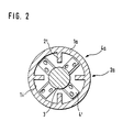
- FIG. 2 shows a cross-sectional view through a lower housing section 1a of the mixing and conveying device according to the invention.
- Opposing guide vanes 2 ⁇ of the first guide wheel 2a are arranged on the inner wall 1i of the housing section 1a.
- the rotor shaft 3 carries four opposing, inclined impeller blades 4 ⁇ , each with two holes. All the impellers 4a, 4b provided on the rotor shaft 3 and all on the inner wall 1i of the housing Section 1a attached guide wheels 2a, 2b are arranged so that the housing part 6 together with the rotor shaft 3 with their bearings 7, 8 and the impellers 4a, 4b can be lifted axially after loosening cylinder screws, not shown here, so that the maintenance and cleaning of the mixing and conveyor is very simplified.
Landscapes
- Chemical & Material Sciences (AREA)
- Chemical Kinetics & Catalysis (AREA)
- Engineering & Computer Science (AREA)
- Mechanical Engineering (AREA)
- Accessories For Mixers (AREA)
- Structures Of Non-Positive Displacement Pumps (AREA)
- Processing And Handling Of Plastics And Other Materials For Molding In General (AREA)
- Mixers Of The Rotary Stirring Type (AREA)
- Feeding, Discharge, Calcimining, Fusing, And Gas-Generation Devices (AREA)
Priority Applications (1)
| Application Number | Priority Date | Filing Date | Title |
|---|---|---|---|
| AT87109850T ATE69995T1 (de) | 1986-07-16 | 1987-07-08 | Kombinierte misch- und foerdereinrichtung fuer hochviskose fluessigkeiten. |
Applications Claiming Priority (2)
| Application Number | Priority Date | Filing Date | Title |
|---|---|---|---|
| DE3623932 | 1986-07-16 | ||
| DE3623932A DE3623932A1 (de) | 1986-07-16 | 1986-07-16 | Kombinierte misch- und foerdereinrichtung fuer hochviskose fluessigkeiten |
Publications (3)
| Publication Number | Publication Date |
|---|---|
| EP0253288A2 true EP0253288A2 (fr) | 1988-01-20 |
| EP0253288A3 EP0253288A3 (en) | 1989-11-29 |
| EP0253288B1 EP0253288B1 (fr) | 1991-12-04 |
Family
ID=6305255
Family Applications (1)
| Application Number | Title | Priority Date | Filing Date |
|---|---|---|---|
| EP87109850A Expired - Lifetime EP0253288B1 (fr) | 1986-07-16 | 1987-07-08 | Dispositif combiné pour mélanger et transporter des liquides très visqueux |
Country Status (4)
| Country | Link |
|---|---|
| US (1) | US4805154A (fr) |
| EP (1) | EP0253288B1 (fr) |
| AT (1) | ATE69995T1 (fr) |
| DE (2) | DE3623932A1 (fr) |
Cited By (6)
| Publication number | Priority date | Publication date | Assignee | Title |
|---|---|---|---|---|
| EP0394007A3 (fr) * | 1989-04-18 | 1992-08-19 | Halliburton Company | Appareil de mélange pour fluides |
| FR2680983A1 (fr) * | 1991-09-10 | 1993-03-12 | Inst Francais Du Petrole | Dispositif melangeur continu, procede et utilisation dans une installation de pompage d'un fluide de forte viscosite. |
| EP0614812A1 (fr) * | 1993-03-12 | 1994-09-14 | Dow Corning Corporation | Ensemble de buse mélangeur |
| CN102059067A (zh) * | 2011-01-17 | 2011-05-18 | 西安华晶电子技术有限公司 | 轴向紊流流型多线切割机用砂浆及高粘流体多轴搅拌器 |
| CN101693171B (zh) * | 2009-10-22 | 2012-04-18 | 天津大学 | 适用于大比例混合的高速动态在线混合装置 |
| WO2016019213A1 (fr) * | 2014-07-31 | 2016-02-04 | Dow Global Technologies Llc | Appareil de mélange dynamique en ligne pour la floculation et la déshydratation de résidus fins de sables bitumineux |
Families Citing this family (20)
| Publication number | Priority date | Publication date | Assignee | Title |
|---|---|---|---|---|
| JPH0710337B2 (ja) * | 1988-07-04 | 1995-02-08 | 三洋化成工業株式会社 | 撹拌装置 |
| US4934828A (en) * | 1989-06-07 | 1990-06-19 | Ciba-Geigy Corporation | Apparatus for mixing viscous materials |
| DE4028108C1 (fr) * | 1990-09-05 | 1992-05-27 | Imcatec-Gmbh Maschinen Fuer Die Verfahrenstechnik, 6800 Mannheim, De | |
| DE4140731C2 (de) * | 1991-12-11 | 2003-12-24 | Teves Gmbh Alfred | Waschanlage, insbesondere für Scheiben eines Kraftfahrzeugs |
| US5304355A (en) * | 1992-09-08 | 1994-04-19 | Quantum Technologies Inc. | Mixer-reactor equipment for treating fine solids with gaseous reagents |
| DE9318098U1 (de) * | 1993-11-26 | 1994-03-17 | Schneider, Friedhelm, 51580 Reichshof | Mischvorrichtung für hochviskose Flüssigkeiten |
| DE19812407A1 (de) * | 1998-03-20 | 1999-09-23 | Michael Marmetschke | Verfahren und Vorrichtung zur Herstellung von Imprägniermitteln |
| RU2184273C2 (ru) * | 2000-07-14 | 2002-06-27 | Открытое акционерное общество "Борец" | Диспергатор погружной насосной установки (варианты) и модуль-секция погружной насосной установки (варианты) |
| US20050040386A1 (en) * | 2001-02-20 | 2005-02-24 | Fow-Sen Choa | Multiple quantum well broad spectrum gain medium and method for forming same |
| DE10141459C2 (de) * | 2001-08-23 | 2003-08-07 | Polymaterials Ag | Verfahren und Vorrichtung zur Herstellung und Prüfung von Formkörpern |
| FR2840546B1 (fr) * | 2002-06-07 | 2005-02-25 | Atofina | Procede pour melanger en contenu dynamiquement au moins deux fluides et micromelangeur |
| DE10242100A1 (de) * | 2002-09-11 | 2004-03-25 | Hennecke Gmbh | Verfahren zur Vermischung einer Polyol- und einer Isocyanatkomponente |
| US20080037361A1 (en) * | 2006-02-15 | 2008-02-14 | Jerry Fleishman | Mixer apparatus |
| ATE467453T1 (de) * | 2006-09-12 | 2010-05-15 | Voss Chemie | Gerätesystem zur herstellung einer gebrauchsfertigen spachtelmasse durch vermischen einer binder- und einer härter-komponente |
| DE202007016136U1 (de) * | 2007-05-31 | 2008-03-27 | Vosschemie Gmbh | Gerät zur Herstellung einer gebrauchsfertigen Spachtelmasse durch Vermischen einer Binder- und einer Härter-Komponente |
| US20080267005A1 (en) * | 2007-04-24 | 2008-10-30 | Tyco Healthcare Group Lp | Applicator system and method of use |
| US8672029B2 (en) * | 2009-12-30 | 2014-03-18 | Schlumberger Technology Corporation | System for reducing foam in mixing operations |
| GB2511476A (en) * | 2012-12-07 | 2014-09-10 | Thomas Andreas Guenther | Device and system for hydrocarbon conversion |
| CN106040065A (zh) * | 2016-05-26 | 2016-10-26 | 广西梧州龙鱼漆业有限公司 | 油漆预分散装置 |
| DE102019103945B4 (de) * | 2019-02-15 | 2022-04-28 | Hennecke Gmbh | Verfahren zur kontinuierlichen Vermischung mindestens einer Polyolkomponente mit mindestens einer Isocyanatkomponete und Rührermischer |
Family Cites Families (18)
| Publication number | Priority date | Publication date | Assignee | Title |
|---|---|---|---|---|
| US214729A (en) * | 1879-04-22 | Improvement in combined churn and ice-cream freezer | ||
| DE575198C (de) * | 1931-08-25 | 1933-04-26 | Steckborn Kunstseide Akt Ges | Vorrichtung zum Herstellen von Emulsionen |
| US2991503A (en) * | 1958-01-06 | 1961-07-11 | Rietz Mfg Co | Breaking, mixing, and extrusion apparatus |
| GB904003A (en) * | 1958-02-06 | 1962-08-22 | Dunlop Rubber Co | Method and apparatus for the production of cellular synthetic rubber |
| GB856708A (en) * | 1958-10-09 | 1960-12-21 | Union Carbide Corp | Method and apparatus for mixing materials forming viscous masses |
| DE1150360B (de) * | 1960-05-09 | 1963-06-20 | Richard Frisse Maschinenfabrik | Knet- und Verreibungsmaschine fuer pastenartige Massen |
| GB1071082A (en) * | 1962-10-25 | 1967-06-07 | Perameters Company Ltd | Improvements in or relating to the manufacture of moulded polyurethane foams |
| US3207486A (en) * | 1963-02-21 | 1965-09-21 | Gabriel Williams Co Inc | Mixing apparatus for quickly reactive components |
| FR1523920A (fr) * | 1967-05-24 | 1968-05-03 | Zink Co John | Dispositif pour mélanger des fluides |
| CH460718A (de) * | 1967-06-22 | 1968-08-15 | Buss Ag | Zusatzeinrichtung an einer Misch- und Kneteinrichtung zur Weiterbehandlung von weichpastösen Produkten |
| US3938783A (en) * | 1970-10-30 | 1976-02-17 | The Upjohn Company | Method for continuous mixing of foam materials |
| GB1390190A (en) * | 1971-07-01 | 1975-04-09 | Wisz E | Mixing apparatus and method |
| US3873072A (en) * | 1971-08-02 | 1975-03-25 | Monsanto Co | Melt extrusion |
| FR2183570A1 (en) * | 1972-05-10 | 1973-12-21 | Serre | Foam polymn and dispensing head - incorporating several rotary impellers for homogenising or expulsion of mixt |
| US3920225A (en) * | 1974-10-01 | 1975-11-18 | Raymond Lee Organization Inc | Centrifugal chemical mixer |
| DE2852499A1 (de) * | 1978-12-05 | 1980-06-19 | Schwing Gmbh F | Mischer fuer dickstoffe, z.b. fuer filterkuchen, schlaemme o.dgl. |
| US4334788A (en) * | 1980-07-15 | 1982-06-15 | Miner Robert M | Pin action mixing pump |
| DE3313710A1 (de) * | 1983-04-15 | 1984-10-18 | Bayer Ag, 5090 Leverkusen | Ruehrvorrichtung |
-
1986
- 1986-07-16 DE DE3623932A patent/DE3623932A1/de not_active Ceased
-
1987
- 1987-07-08 AT AT87109850T patent/ATE69995T1/de active
- 1987-07-08 DE DE8787109850T patent/DE3774949D1/de not_active Expired - Lifetime
- 1987-07-08 EP EP87109850A patent/EP0253288B1/fr not_active Expired - Lifetime
- 1987-07-09 US US07/071,990 patent/US4805154A/en not_active Expired - Lifetime
Cited By (10)
| Publication number | Priority date | Publication date | Assignee | Title |
|---|---|---|---|---|
| EP0394007A3 (fr) * | 1989-04-18 | 1992-08-19 | Halliburton Company | Appareil de mélange pour fluides |
| FR2680983A1 (fr) * | 1991-09-10 | 1993-03-12 | Inst Francais Du Petrole | Dispositif melangeur continu, procede et utilisation dans une installation de pompage d'un fluide de forte viscosite. |
| EP0532397A1 (fr) * | 1991-09-10 | 1993-03-17 | Institut Francais Du Petrole | Dispositif mélangeur continu, procédé et utilisation dans une installation de pompage d'un fluide de haute viscosité |
| US5320500A (en) * | 1991-09-10 | 1994-06-14 | Institut Francais Du Petrole | Continuous mixing device, method and use in an installation for pumping a high viscosity fluid |
| EP0614812A1 (fr) * | 1993-03-12 | 1994-09-14 | Dow Corning Corporation | Ensemble de buse mélangeur |
| AU665300B2 (en) * | 1993-03-12 | 1995-12-21 | Dow Corning Corporation | Nozzle mixer assembly |
| CN101693171B (zh) * | 2009-10-22 | 2012-04-18 | 天津大学 | 适用于大比例混合的高速动态在线混合装置 |
| CN102059067A (zh) * | 2011-01-17 | 2011-05-18 | 西安华晶电子技术有限公司 | 轴向紊流流型多线切割机用砂浆及高粘流体多轴搅拌器 |
| CN102059067B (zh) * | 2011-01-17 | 2011-10-26 | 西安华晶电子技术股份有限公司 | 轴向紊流流型多线切割机用砂浆及高粘流体多轴搅拌器 |
| WO2016019213A1 (fr) * | 2014-07-31 | 2016-02-04 | Dow Global Technologies Llc | Appareil de mélange dynamique en ligne pour la floculation et la déshydratation de résidus fins de sables bitumineux |
Also Published As
| Publication number | Publication date |
|---|---|
| US4805154A (en) | 1989-02-14 |
| EP0253288A3 (en) | 1989-11-29 |
| ATE69995T1 (de) | 1991-12-15 |
| DE3774949D1 (de) | 1992-01-16 |
| DE3623932A1 (de) | 1988-01-21 |
| EP0253288B1 (fr) | 1991-12-04 |
Similar Documents
| Publication | Publication Date | Title |
|---|---|---|
| EP0253288B1 (fr) | Dispositif combiné pour mélanger et transporter des liquides très visqueux | |
| DE1158480B (de) | Drehkegelmischer | |
| DE3304129A1 (de) | Verfahren und mischer zum kontinuierlichen beleimen von aus holz-spaenen, -fasern od. dgl. bestehendem mischgut | |
| DE3809661A1 (de) | Vorrichtung zum kontinuierlichen mischen eines baustoffs | |
| EP0090257A2 (fr) | Dispositif pour la production d'un mélange chimiquement réactif d'au moins deux composants plastiques liquides | |
| DE2028336C3 (de) | Vorrichtung zum Sieben wäßriger Aufschlämmungen, insbesondere Faserstoffaufschlämmungen | |
| DE2418967C2 (de) | Exzenterschneckenpumpe | |
| EP2035126B1 (fr) | Dispositif homogénéisateur avec des couronnes dentées logées horizontalement | |
| DE202016000169U1 (de) | Pump- und/oder Mischeinrichtung zum Fördern, Homogenisieren und/oder Dispergieren fließfähiger Produkte | |
| DE6910964U (de) | Mischvorrichtung | |
| DE3342304A1 (de) | Homogenisiermaschine | |
| DE1557184A1 (de) | Vorrichtung zum kontinuierlichen Mischen,Homogenisieren und Belueften von pastoesen Massen,insbesondere Schokoladenmassen | |
| EP0716878B1 (fr) | Dispositif de fabrication de peinture | |
| DE3612853C2 (fr) | ||
| AT395872B (de) | Vorrichtung zum sieben einer zellulosefaserbrei-suspension | |
| DE2905665C2 (de) | Schneckenförderer | |
| DE19719638C2 (de) | Vorrichtung zum Einmischen von Flockungsflüssigkeit in eine Klärschlamm-Strömung und Anwendung der Vorrichtung | |
| EP1106242A2 (fr) | Réacteur à boucles | |
| DE1224138B (de) | Bleichturm für Zellstoff | |
| DE29716298U1 (de) | Förderpumpe | |
| DE9305553U1 (de) | Homogenisiervorrichtung o.dgl. | |
| DE3406648A1 (de) | Mischmaschine fuer kontinuierliche mischverfahren | |
| DE69730068T2 (de) | Mischvorrichtung | |
| DE1272894B (de) | Vorrichtung zum Mischen eines pulverfoermigen Stoffes mit einer Fluessigkeit | |
| DE19821516A1 (de) | Einrichtung zum Durchtränken und Feststoffen mit Flüssigkeiten zur Herstellung von extrudierten Nahrungsmitteln |
Legal Events
| Date | Code | Title | Description |
|---|---|---|---|
| PUAI | Public reference made under article 153(3) epc to a published international application that has entered the european phase |
Free format text: ORIGINAL CODE: 0009012 |
|
| AK | Designated contracting states |
Kind code of ref document: A2 Designated state(s): AT BE CH DE FR GB IT LI NL SE |
|
| PUAL | Search report despatched |
Free format text: ORIGINAL CODE: 0009013 |
|
| AK | Designated contracting states |
Kind code of ref document: A3 Designated state(s): AT BE CH DE FR GB IT LI NL SE |
|
| 17P | Request for examination filed |
Effective date: 19900119 |
|
| 17Q | First examination report despatched |
Effective date: 19901011 |
|
| GRAA | (expected) grant |
Free format text: ORIGINAL CODE: 0009210 |
|
| ITF | It: translation for a ep patent filed | ||
| AK | Designated contracting states |
Kind code of ref document: B1 Designated state(s): AT BE CH DE FR GB IT LI NL SE |
|
| REF | Corresponds to: |
Ref document number: 69995 Country of ref document: AT Date of ref document: 19911215 Kind code of ref document: T |
|
| REF | Corresponds to: |
Ref document number: 3774949 Country of ref document: DE Date of ref document: 19920116 |
|
| GBT | Gb: translation of ep patent filed (gb section 77(6)(a)/1977) | ||
| ET | Fr: translation filed | ||
| PLBE | No opposition filed within time limit |
Free format text: ORIGINAL CODE: 0009261 |
|
| STAA | Information on the status of an ep patent application or granted ep patent |
Free format text: STATUS: NO OPPOSITION FILED WITHIN TIME LIMIT |
|
| 26N | No opposition filed | ||
| PGFP | Annual fee paid to national office [announced via postgrant information from national office to epo] |
Ref country code: CH Payment date: 19930706 Year of fee payment: 7 |
|
| PGFP | Annual fee paid to national office [announced via postgrant information from national office to epo] |
Ref country code: SE Payment date: 19930707 Year of fee payment: 7 |
|
| PGFP | Annual fee paid to national office [announced via postgrant information from national office to epo] |
Ref country code: GB Payment date: 19930708 Year of fee payment: 7 |
|
| PGFP | Annual fee paid to national office [announced via postgrant information from national office to epo] |
Ref country code: AT Payment date: 19930723 Year of fee payment: 7 |
|
| PG25 | Lapsed in a contracting state [announced via postgrant information from national office to epo] |
Ref country code: GB Effective date: 19940708 Ref country code: AT Effective date: 19940708 |
|
| PG25 | Lapsed in a contracting state [announced via postgrant information from national office to epo] |
Ref country code: SE Effective date: 19940709 |
|
| PG25 | Lapsed in a contracting state [announced via postgrant information from national office to epo] |
Ref country code: LI Effective date: 19940731 Ref country code: CH Effective date: 19940731 |
|
| EUG | Se: european patent has lapsed |
Ref document number: 87109850.5 Effective date: 19950210 |
|
| GBPC | Gb: european patent ceased through non-payment of renewal fee |
Effective date: 19940708 |
|
| REG | Reference to a national code |
Ref country code: CH Ref legal event code: PL |
|
| EUG | Se: european patent has lapsed |
Ref document number: 87109850.5 |
|
| PGFP | Annual fee paid to national office [announced via postgrant information from national office to epo] |
Ref country code: FR Payment date: 20010628 Year of fee payment: 15 |
|
| PGFP | Annual fee paid to national office [announced via postgrant information from national office to epo] |
Ref country code: BE Payment date: 20010709 Year of fee payment: 15 |
|
| PGFP | Annual fee paid to national office [announced via postgrant information from national office to epo] |
Ref country code: DE Payment date: 20010726 Year of fee payment: 15 |
|
| PGFP | Annual fee paid to national office [announced via postgrant information from national office to epo] |
Ref country code: NL Payment date: 20010731 Year of fee payment: 15 |
|
| PG25 | Lapsed in a contracting state [announced via postgrant information from national office to epo] |
Ref country code: BE Free format text: LAPSE BECAUSE OF NON-PAYMENT OF DUE FEES Effective date: 20020731 |
|
| BERE | Be: lapsed |
Owner name: *SCHNEIDER FRIEDHELM Effective date: 20020731 |
|
| PG25 | Lapsed in a contracting state [announced via postgrant information from national office to epo] |
Ref country code: NL Free format text: LAPSE BECAUSE OF NON-PAYMENT OF DUE FEES Effective date: 20030201 Ref country code: DE Free format text: LAPSE BECAUSE OF NON-PAYMENT OF DUE FEES Effective date: 20030201 |
|
| PG25 | Lapsed in a contracting state [announced via postgrant information from national office to epo] |
Ref country code: FR Free format text: LAPSE BECAUSE OF NON-PAYMENT OF DUE FEES Effective date: 20030331 |
|
| NLV4 | Nl: lapsed or anulled due to non-payment of the annual fee |
Effective date: 20030201 |
|
| REG | Reference to a national code |
Ref country code: FR Ref legal event code: ST |
|
| PG25 | Lapsed in a contracting state [announced via postgrant information from national office to epo] |
Ref country code: IT Free format text: LAPSE BECAUSE OF NON-PAYMENT OF DUE FEES;WARNING: LAPSES OF ITALIAN PATENTS WITH EFFECTIVE DATE BEFORE 2007 MAY HAVE OCCURRED AT ANY TIME BEFORE 2007. THE CORRECT EFFECTIVE DATE MAY BE DIFFERENT FROM THE ONE RECORDED. Effective date: 20050708 |