EP0253433A2 - Verzögerungseinrichtung für Auslöseelemente elektrischer Schalter - Google Patents
Verzögerungseinrichtung für Auslöseelemente elektrischer Schalter Download PDFInfo
- Publication number
- EP0253433A2 EP0253433A2 EP87201263A EP87201263A EP0253433A2 EP 0253433 A2 EP0253433 A2 EP 0253433A2 EP 87201263 A EP87201263 A EP 87201263A EP 87201263 A EP87201263 A EP 87201263A EP 0253433 A2 EP0253433 A2 EP 0253433A2
- Authority
- EP
- European Patent Office
- Prior art keywords
- delaying
- lever
- drum
- constituted
- circuit breaker
- Prior art date
- Legal status (The legal status is an assumption and is not a legal conclusion. Google has not performed a legal analysis and makes no representation as to the accuracy of the status listed.)
- Ceased
Links
Images

Classifications
-
- H—ELECTRICITY
- H01—ELECTRIC ELEMENTS
- H01H—ELECTRIC SWITCHES; RELAYS; SELECTORS; EMERGENCY PROTECTIVE DEVICES
- H01H71/00—Details of the protective switches or relays covered by groups H01H73/00 - H01H83/00
- H01H71/10—Operating or release mechanisms
- H01H71/12—Automatic release mechanisms with or without manual release
- H01H71/44—Automatic release mechanisms with or without manual release having means for introducing a predetermined time delay
- H01H71/446—Automatic release mechanisms with or without manual release having means for introducing a predetermined time delay making use of an inertia mass
Definitions
- the object of the present invention is a delaying device for release elements of electrical circuits.
- circuit breakers are provided with release elements which, in case of anomalous conditions of power supply, perform their tripping action, generally for protecting the circuits downstream them (both whether such circuits are true circuits, or loads).
- the release elements which are mechanically linked to the retainer elements of the circuit breaker, cause the switching off of this latter.
- release elements two types can be distinguished, viz., the instantaneous release elements, and the release elements with a fixed delay time (these latter perform their tripping function with a preset fixed delay time).
- the delay in the tripping action is generally determined by wheelworks or by bimetallic elements, which determine extremely variable release times, sometimes not justified from the view point of an efficacious and rational protection of the circuits.
- a not least disadvantage is the non-reliability and the non-repeatitivity of the switching actions, in as much as, the higher and the more complex the moving masses, the greater the maintainance and breakage problems, and the shorter the operating life of said devices.
- the purpose of the present invention is obviating the disadvantages due to the above cited devices known from the prior art, by providing a release device which is very simple from the structural viewpoint, and can be produced hence at low costs, and is endowed with high reliability characteristics.
- a delaying device for release elements of electrical circuit breakers, which is essentially constituted, in a circuit breaker structure, by at least a coil connected in series to a main circuit of a circuit breaker, said at least one coil actuating, when electrical power is supplied to it, at least an elastically-swinging lever capable of rotating a release shaft causing the tripping of said circuit breaker, said shaft being provided with at least one tongue suitable to engage said at least one lever, characterized in that said delaying device is constituted by first delaying lever means elastically mounted on said release shaft, and acting on second delaying means of the delaying mass type, fastened onto said circuit breaker structure in correspondence of said first delaying lever means.
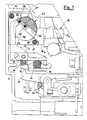
- a delaying device according to the invention is generally indicated, which is inserted inside a circuit breaker structure 11, of which only one release element, generally indicated in 12, is visible.
- the delaying device 10 is basically formed by two parts: a first part, constituted by a lever 13, having a substantially "L"-shape, mounted on the release shaft 14 of the circuit breaker 11 by means of a slot 15.
- the shaft 14 is equipped with a tongue 16 having a substantially trapezoidal section.
- a helical spring 18 is provided, which, together with the slot 15, allows an elastical backlash between the shaft 14 and the tongue 13.
- the second part of device 10 which constitutes the delaying mass, consists of a support 19 fastened onto the structure 11 in an upper position relatively to shaft 14, and constituted by two laminar elements 19a and 19b (NOTE: of element 19b, only an end, on-sight, portion is shown, whilst element 19a is totally visible), constrained by means of connecting pins 20 and 21.
- a drum 23 is eccentrically hinged in 22.
- the drum 23 is provided with a groove 24 inside which a pin 25, protruding from the base surfaces 26 of drum 23 is transversely housed.
- the pin 25 limits the rotation of the drum, by being in engagement with sliding seats 27 provided on each one of the elements of support 19.
- a torsion spring 29 is provided.
- lever 13 An upper portion 30 of lever 13 is in engagement with pin 25, so that, when the release element 12 acts on tongue 16, by means of a toothed lever 31 thereof, the release shaft 14 cannot cause the opening of the circuit breaker until the lever 13 has not won the elastic force of the spring 18, and of the delaying mass constituted by the drum 23 eccentrically movable on the support 19.
- the spring 18 can be replaced by any other elastic means, such as, e.g., a leaf spring 50 having a suitable stiffness, directly inserted in the structure of lever 13 ( Figure 2).
Landscapes
- Breakers (AREA)
Applications Claiming Priority (2)
| Application Number | Priority Date | Filing Date | Title |
|---|---|---|---|
| IT2252586U IT207943Z2 (it) | 1986-07-15 | 1986-07-15 | Dispositivo ritardatore persganciatori di interrutori elettrici. |
| IT2252586U | 1986-07-15 |
Publications (2)
| Publication Number | Publication Date |
|---|---|
| EP0253433A2 true EP0253433A2 (de) | 1988-01-20 |
| EP0253433A3 EP0253433A3 (de) | 1988-10-12 |
Family
ID=11197436
Family Applications (1)
| Application Number | Title | Priority Date | Filing Date |
|---|---|---|---|
| EP87201263A Ceased EP0253433A3 (de) | 1986-07-15 | 1987-07-03 | Verzögerungseinrichtung für Auslöseelemente elektrischer Schalter |
Country Status (2)
| Country | Link |
|---|---|
| EP (1) | EP0253433A3 (de) |
| IT (1) | IT207943Z2 (de) |
Family Cites Families (5)
| Publication number | Priority date | Publication date | Assignee | Title |
|---|---|---|---|---|
| US1774966A (en) * | 1926-05-15 | 1930-09-02 | Gen Electric | Time-element device |
| FR46510E (fr) * | 1935-03-06 | 1936-07-09 | App G M N | Perfectionnement aux interrupteurs électriques automatiques |
| FR2101029B1 (de) * | 1970-08-10 | 1973-11-23 | Merlin Gerin | |
| FR2431181A2 (fr) * | 1978-07-10 | 1980-02-08 | Merlin Gerin | Disjoncteur equipe d'un temporisateur a inertie |
| US4237436A (en) * | 1979-01-15 | 1980-12-02 | Heinemann Electric Company | Circuit breaker having a modified armature for time delays at high transient currents |
-
1986
- 1986-07-15 IT IT2252586U patent/IT207943Z2/it active
-
1987
- 1987-07-03 EP EP87201263A patent/EP0253433A3/de not_active Ceased
Also Published As
| Publication number | Publication date |
|---|---|
| EP0253433A3 (de) | 1988-10-12 |
| IT8622525V0 (it) | 1986-07-15 |
| IT207943Z2 (it) | 1988-03-14 |
Similar Documents
| Publication | Publication Date | Title |
|---|---|---|
| US4480242A (en) | Variable torque contact arm for electric circuit breakers | |
| EP1356488B1 (de) | Justiervorrichtung für einen thermischen auslöser | |
| CA1110302A (en) | Circuit breaker having improved movable contact position indicator | |
| EP0253433A2 (de) | Verzögerungseinrichtung für Auslöseelemente elektrischer Schalter | |
| US5258732A (en) | Overload relay | |
| US4859979A (en) | Thermal relay | |
| US3944959A (en) | Electrical circuit breaker | |
| US3249720A (en) | Thermal trip unit with calibrating adjustment | |
| EP0437553A1 (de) | Selbstcoordinierendes schaltschutzgerät für elektrische apparate. | |
| US3175064A (en) | Shunt trip and under voltage device | |
| CA2026365C (en) | Overload relay | |
| US3622923A (en) | Electromagnetic device for circuit breaker trip assembly unit | |
| DE4202049C1 (de) | Thermischer Auslöser für elektrische Schaltgeräte | |
| US3290474A (en) | Circuit interrupter with improved terminal connecting means | |
| US3408606A (en) | Low ampere circuit breaker with indirectly heated thermal element | |
| US2549794A (en) | Control switch | |
| US2689285A (en) | Circuit breaker | |
| US2934624A (en) | Bi-directionally releasable circuit breaker | |
| EP3282520B1 (de) | Hilfskontaktanordnung | |
| US1360280A (en) | Circuit-breaker | |
| US3171932A (en) | Multipole electric circuit breaker with common tripping means | |
| US2662951A (en) | Electric circuit breaker | |
| WO1997019459A1 (en) | Device in a safety switch | |
| US2866035A (en) | Thermally operated electric switching mechanisms | |
| US4794357A (en) | Multi-pole circuit interrupter |
Legal Events
| Date | Code | Title | Description |
|---|---|---|---|
| PUAI | Public reference made under article 153(3) epc to a published international application that has entered the european phase |
Free format text: ORIGINAL CODE: 0009012 |
|
| AK | Designated contracting states |
Kind code of ref document: A2 Designated state(s): BE CH DE FR GB LI NL SE |
|
| PUAL | Search report despatched |
Free format text: ORIGINAL CODE: 0009013 |
|
| AK | Designated contracting states |
Kind code of ref document: A3 Designated state(s): BE CH DE FR GB LI NL SE |
|
| 17P | Request for examination filed |
Effective date: 19890203 |
|
| 17Q | First examination report despatched |
Effective date: 19910708 |
|
| STAA | Information on the status of an ep patent application or granted ep patent |
Free format text: STATUS: THE APPLICATION HAS BEEN REFUSED |
|
| 18R | Application refused |
Effective date: 19920920 |
|
| RIN1 | Information on inventor provided before grant (corrected) |
Inventor name: MOSTOSI, ANGELO |