EP0253467A2 - Einrichtung zum Trennen von Gasen und Flüssigkeiten - Google Patents
Einrichtung zum Trennen von Gasen und Flüssigkeiten Download PDFInfo
- Publication number
- EP0253467A2 EP0253467A2 EP87303011A EP87303011A EP0253467A2 EP 0253467 A2 EP0253467 A2 EP 0253467A2 EP 87303011 A EP87303011 A EP 87303011A EP 87303011 A EP87303011 A EP 87303011A EP 0253467 A2 EP0253467 A2 EP 0253467A2
- Authority
- EP
- European Patent Office
- Prior art keywords
- blood
- foam
- bubbles
- liquid
- antifoaming agent
- Prior art date
- Legal status (The legal status is an assumption and is not a legal conclusion. Google has not performed a legal analysis and makes no representation as to the accuracy of the status listed.)
- Granted
Links
Images

Classifications
-
- B—PERFORMING OPERATIONS; TRANSPORTING
- B01—PHYSICAL OR CHEMICAL PROCESSES OR APPARATUS IN GENERAL
- B01D—SEPARATION
- B01D19/00—Degasification of liquids
- B01D19/0031—Degasification of liquids by filtration
-
- A—HUMAN NECESSITIES
- A61—MEDICAL OR VETERINARY SCIENCE; HYGIENE
- A61M—DEVICES FOR INTRODUCING MEDIA INTO, OR ONTO, THE BODY; DEVICES FOR TRANSDUCING BODY MEDIA OR FOR TAKING MEDIA FROM THE BODY; DEVICES FOR PRODUCING OR ENDING SLEEP OR STUPOR
- A61M1/00—Suction or pumping devices for medical purposes; Devices for carrying-off, for treatment of, or for carrying-over, body-liquids; Drainage systems
- A61M1/36—Other treatment of blood in a by-pass of the natural circulatory system, e.g. temperature adaptation, irradiation ; Extra-corporeal blood circuits
- A61M1/3621—Extra-corporeal blood circuits
- A61M1/3627—Degassing devices; Buffer reservoirs; Drip chambers; Blood filters
-
- B—PERFORMING OPERATIONS; TRANSPORTING
- B01—PHYSICAL OR CHEMICAL PROCESSES OR APPARATUS IN GENERAL
- B01D—SEPARATION
- B01D19/00—Degasification of liquids
- B01D19/02—Foam dispersion or prevention
Definitions
- This invention relates to a system useful for the separation of liquid and gas, and more particularly to a medical device, such as a blood oxygenator or a cardiotomy reservoir, which employs a defoamer system that affords excellent separation of macroscopic and microscopic air from blood while at the same time minimizing blood path contact with the silicone containing compounds typically used in the defoamer.
- a medical device such as a blood oxygenator or a cardiotomy reservoir
- oxygenators are used in open-heart surgery and other operations and treatments of the body when it is necessary to establish an extracorporeal circulation system for temporarily assuming the functions of the heart and lungs of the patient.
- the oxygenator operates to perform the function usually performed by the lungs of the patient, i.e., the life-supporting transfer of oxygen into the blood and carbon dioxide out of the blood.
- the oxygenator is used in association with a pump which performs the function of the heart to cause circulation of the blood.
- a pump which performs the function of the heart to cause circulation of the blood.
- the early heart-lung machines were typically rotating discs which passed through a pool of blood, but were only partially immersed therein such that the free surface of the disc exposed the blood to oxygen and accomplished some gas transfer. After this, bag-type oxygenators were introduced which were superior to the disc oxygenators, but which left much to be desired.
- a membrane oxygenator a thin, highly gas permeable membrane is placed between the gas and blood. Venous blood flows along one side of the membrane and gas is on the other side. A pressure gradient is established so that when the partial pressure for oxygen is higher in the ventilating gas than the partial pressure for oxygen in the venous blood, oxygen will diffuse across the membrane into the blood. Bubble oxygenators simply diffuse gas bubbles into venous blood. The oxygenated blood is typically defoamed before it is ready for delivery to the patient.
- air or some other gas can be introduced into the blood, e.g. oxygen (in an oxygenator), nitrogen, carbon dioxide, etc.
- oxygen in an oxygenator
- nitrogen in an oxygenator
- carbon dioxide etc.
- a defoaming device typically incorporates some sort of an agent to assist in breaking the foam down.
- silicone antifoam agent about the only agent that has proved acceptable is a silicone antifoam agent.
- silicone is not metabolized by the human body, and therefore silicone accumulates in the body. Even though silicone is an inert material it is undesirable within the human body because it can tend to clog up some of the very small capillaries and arteries within the human body.
- the features of the present invention can be employed in various types of medical devices.
- Examples of the type of so-called membrane oxygenators which can employ the features of the present invention are described in U.S. Patent Numbers 4,094,792 and 4,196,075 both of which are assigned to Bentley Laboratories, Inc., the assignee of the present invention.
- Bentley Laboratories, Inc. products identified as the Bentley BCM-3 and BCM-7 integrated membrane oxygenators which are oxygenators having three major components can incorporate the defoamer of the present invention.
- Examples of the bubble type blood oxygenator that can employ the features of the present invention are described in U.S.
- Another object of the present invention is to provide a defoaming device which has particular use with a medical device such as an oxygenator for the removal of gases, such as oxygen, from blood.
- Still another object of the present invention is to provide a defoaming device which employs a silicone antifoam agent to assist in breaking the foam (bubbles) in the blood down, and which at the same time substantially avoids contaminating the blood with undesirable silicone.
- Still another object of the present invention is to provide a defoaming device for separating gases from blood which employs a silicone antifoam agent and in which the blood contacts the silicone antifoam agent only when there is gas in the blood.
- a defoaming device for separating gas in the form of foam from the liquid and then breaking the foam down into a liquid and a gas.
- the device comprises a reservoir and a filtering element that does not contain an antifoaming agent and which is positioned in the lower portion of the reservoir to first contact the liquid and separate gas foam and bubbles from the liquid.
- an element containing an antifoaming agent Positioned in the reservoir above the maximum fluid level is an element containing an antifoaming agent which then comes in contact with the foam that rise from the filtering element and breaks down the foam.
- the blood when the blood is moving through a medical device it may from time to time have some gas in it.
- an antifoam agent such as a silicone material (e.g. simethicone) is typically used.
- a silicone material e.g. simethicone
- the defoamer device in accordance with the features of the present invention is unique in that when in operation, blood without gas will not contact the silicone containing material.
- Foam, macroscopic bubbles, and microscopic bubbles, appearing in the blood will be separated from the blood without contacting the silicone antifoam agent, Then, after separation, the foam and bubbles are allowed to travel to a portion of the defoamer assembly positioned above the maximum level of blood in the assembly's reservoir where the foam and bubbles are then placed in contact with an antifoam dipped material.
- the present invention is unique because it defines a defoamer which allows selective exposure of only the foam and bubbles to an antifoaming agent.
- the defoaming device in accordance with the invention can be used for removing a gas, such as air, from various types of fluids, such as blood.
- a gas such as air
- the defoamer system as described herein is particularly suited for use in any open system device which requires air-blood separation. Excellent opportunities for using this defoamer system thereby exist in such medical devices as, for example, bubble oxygenators, membrane oxygenators, cardiotomies, hardshell venous reservoirs, blood autotransfusion systems and oxygenated blood cardioplegia systems.
- the defoaming device in accordance with the present invention will be described below with regard to its use in an oxygenator for the purpose of removing gas foam and bubbles from blood, it is to be understood that the defoaming device has broader use, does not require the particular structural features of the particular embodiment described herein and is capable of removing various gases from different liquids when used with a medical device and in other enviroments.
- the basic features of a preferred embodiment of the defoaming device 10 of this invention are shown in Figure 1.
- the device illustrated can be identified as either the Bentley Laboratories, Inc. BCM-3 or BCM-7 defoamer which can be used, for example, in either the Bentley BCM-3 or BCM-7 integrated membrane oxygenator as described in commonly assigned and copending Serial No. , filed , (Docket Number MM:550) entitled "Integrated Membrane Oxygenator, Heat Exchanger and Reservoir or in the Bentley BMR-1500 membrane oxygenator reservoir.
- the defoamer device 10 is a three-piece assembly which affords excellent separation of foam and macroscopic and microscopic air from blood while minimizing blood path contact with the silicone containing antifoam compound that is employed in the device.
- the three primary components of the defoamer device 10 shown in Figure 1 are as follows: (a) A low antifoam dipped (only on the top portion thereof 11,) polyurethane, thermally reticulated (open cell), foam pre-stage 11A constructed, for example, from 1/2 inch thick, 100 ppi (pores per inch) polyurethane; (b) a screen 12 which can be a heparin coated 50 micron (mesh opening in microns) monodur polyester screen having a 36 percent open area (twill weave); and (c) a foam spacer stage 13 which which can be a 1/8 inch thick, 15 ppi polyurethane, thermally reticulated (open cell) foam spacer stage.
- the polyurethane foam pre-stage 11 is the only element of defoamer device 10 which includes an antifoaming agent.
- an antifoam compound e.g. simethicone
- contact between the blood and the silicone coating antifoam agent is minimized i.e.
- defoaming device 10 When defoaming device 10 is employed in an oxygenator, during normal operation the maximum blood column height within the defoamer remains below the lower margin area of the element 11 which contains the antifoam material. Microbubbles are not significantly affected by the simethicone compound or other antifoaming agents and exposure of the whole blood path to the antifoaming agents is unnecessary.
- the defoaming device 10 allows selective exposure of only blood foam to an antifoaming agent.
- the 100 ppi polyurethane foam pre-stage 11A acts to filter foam, macroscopic air bubbles and microscopic air bubbles appearing in the blood before its presentation to the heparin coated polyester microscreen 12.
- the microscreen 12 is capable of removing the macroscopic air which is first presented to the pre-stage polyurethane foam 11, doing so causes an occlusive air film to form on the screen.
- Exposure of microscreens to large amounts of macroscopic air decreases their effective surface area and can impede their ability to pass fluids, even when treated with wetting agents such as heparin.
- a possible consequence of air occlusion of these microscreens is that blood passing through the diminished screen area is subjected to increased flow resistance and pressure drop. These increases may produce blood formed elements damage.
- Placement of a polyurethane foam "filtering stage" prior to the heparin coated screen significantly improves the blood air elimination as well as the blood handling capability of the defoamer assembly.
- the heparin coated microscreen 12 does not enclose the upper portion of the polyurethane foam 11.
- the blood level within the defoamer will always be below the margin of the polyester microscreen. Should the screen 12 become occluded, the blood level within the defoamer will exceed the height of the screen and blood flow will bypass the screen. All blood flow will pass through the antifoam treated section of the polyurethane defoamer 11 and cascade over the occluded microscreen.
- This integral bypass feature of the defoamer assembly 10 is a crucial safety feature which allows the use of a microscreen in the blood path without the threat of total blood path occlusion concommitant with screen occlusion.
- the third element of the defoamer assembly 10 is a spacer stage 13 which is preferably a 1/8 inch thick 15 ppi polyurethane, thermally reticulated (open cell) material.
- This element is a spacer stage which prevents the wicking of blood between the polyester microscreen 12 (or the upper segment of the 100 ppi prestage 11) and the outer containment layer, e.g. a polyester tricot stock, in which the elements of the defoamer assembly are enclosed.
- a large pore material, such as a 15 ppi polyurethane material 13 is preferably used for this spacer stage to limit material surface area for air and blood remixing.
- All three elements 11A, 12, and 13 are preferably located in a polyester tricot sock 14 outer layer and the entire defoaming assembling is secured onto a rigid vented support grid 15.
- the stock 14 and screen element 12 are connected to straps at positions 16 and 17 in the manner as described herein below, i.e. the example given of how the defoaming assembly 10 can be used in a membrane oxygenator.
- defoamer assembly 10 there are certain critical parameters which will enable the defoamer assembly to operate in the environment of an oxygenator, particularly a membrane oxygenator, in an efficient manner.
- the polyurethane foam 11,11A and 13 and polyester screen 12 pore sizes are critical to the efficient functioning of the entire assembly.
- a preferred pore size for the material is about 100 ppi and this pore size can range from about 80 to 110 ppi. It is preferred not to use foam for element 11 having a pore size less than about 80 ppi because this type of material will not adequately screen macroscopic air. If the pore size of element 11A is greater than about 110 ppi it may have too high a breakthrough volume thereby bringing the blood path in contact with antifoaming agents.
- a preferred pore size for the screen material is about 50 microns and can range from about 50 to 71 microns.
- a screen having less than about 50 micron openings because this type of microscreen has an inadequate percent of open area. A low percent of open area may produce unacceptable levels of blood damage. If the screen has greater than about 71 micron openings, it will exhibit little effect in reducing microbubble levels.
- a preferred pore size is about 15 ppi and this can range from about 15 to 25 ppi. It is preferred not to use a foam spacer stage 13 having a ppi call out less than about 15 ppi because it is difficult to manufacture defoamer material with this low pore size. Polyurethane foam material with a ppi call out greater than about 25 ppi is generally not acceptable because it presents too much material surface area for air/blood remixing.
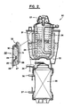
- a membrane oxygenator 20 with the circled area 21 illustrating in an enlarged manner the structure of a defoaming assembly 21 incorporating the unique features of the present invention.
- blood from a patient is fed into the membrane oxygenator through a venous inlet connector located at the top portion 23 of the oxygenator.
- the blood slowly trickles in a downward direction onto the heat exchanger tubes 24, which are preferably in the form of a helically wrapped tube, and then into the defoaming assembly 22.
- the purpose of passing the blood through the defoaming assembly is to separate incidental air that is fed into the oxygenator along with the blood.
- the defoaming assembly 22 is structured of an outer layer of a polyester tricot sock 25. Located adjacent sock 25 is a layer 26 of a 15 ppi polyurethane foam material. A 50 micron modur polyester screen 27 is positioned between foam material 26 and layer 28 of 100 ppi polyurethane foam material. A strap member (not shown) is secured to screen 27 at position 29 and used to squeeze foam layer 28 inwardly (as shown) at the approximate location of the maximum blood level within the defoaming assembly. The 100 ppi polyurethane foam material 30 positioned above this indented portion of the 100 ppi foam (i.e.
- defoaming assembly 22 positioned above the maximum surface of the blood level within the defoaming assembly) is the portion of the 100 ppi foam material which includes an antifoaming agent such as, for example, simethicone.
- the next illustrated layer of defoaming assembly 22 represents a suppport grid 31. Another strap element is secured to the sock 25 at position 32 and holds the sock onto the support grid.
- the blood travels from the heat exchange tubes 24 and is directed into contact with the 100 ppi polyurethane foam prestage 28 (that part of the 100 ppi foam without the antifoaming agent) which acts to filter foam, macroscopic air bubbles, and microscopic air bubbles appearing in the blood.
- the blood travels to the heparin coated polyester microscreen 27 which effectively eliminates the microbubbles of air in the blood greater than 50 microns in diameter.
- the microbubbles separated from the blood and any other foam travel to the antifoam area 30 of the 100 ppi polyurethane foam which is located above the maximum surface level of the blood when the separation of the air from blood occurs.
- the defoamer allows selective exposure of only blood foam (bubbles) to the antifoaming agent.
- the blood After the blood passes through the defoaming assembly 22, it goes into a venous reservoir 33. Thereafter, the blood passes from the reservoir out of a venous reservoir outlet connector 34 to a pump (not shown) which pumps the blood back to the lower portion of oxygenator 20 through an oxygenator inlet connector (not shown). It is in the lower portion of the membrane oxygenator where oxygen transfer to the blood actually occurs.
- the blood After being pumped back into the oxygenator, the blood flows thru a plurality of vertical hollow fibers 35.
- the oxygenator includes an oxygen inlet connector 37 which feeds the oxygen to fibers 35 and an oxygen outlet connector 36 which allow the oxygen to travel out of the oxygenator. Basically the blood flows through the fibers 35 while the oxygen flows around the hollow fibers whereby the oxygenation takes place.
- the apparatus described in accordance with the present invention can be used to defoam numerous types of liquids.
- a liquid is blood, which has been used as a specific example to described a detailed embodiment of the present invention.
Landscapes
- Health & Medical Sciences (AREA)
- Chemical & Material Sciences (AREA)
- Chemical Kinetics & Catalysis (AREA)
- Heart & Thoracic Surgery (AREA)
- Vascular Medicine (AREA)
- Biomedical Technology (AREA)
- Engineering & Computer Science (AREA)
- Anesthesiology (AREA)
- Cardiology (AREA)
- Hematology (AREA)
- Life Sciences & Earth Sciences (AREA)
- Animal Behavior & Ethology (AREA)
- General Health & Medical Sciences (AREA)
- Public Health (AREA)
- Veterinary Medicine (AREA)
- Dispersion Chemistry (AREA)
- External Artificial Organs (AREA)
Applications Claiming Priority (2)
| Application Number | Priority Date | Filing Date | Title |
|---|---|---|---|
| US88596386A | 1986-07-14 | 1986-07-14 | |
| US885963 | 1986-07-14 |
Publications (3)
| Publication Number | Publication Date |
|---|---|
| EP0253467A2 true EP0253467A2 (de) | 1988-01-20 |
| EP0253467A3 EP0253467A3 (en) | 1990-06-20 |
| EP0253467B1 EP0253467B1 (de) | 1993-11-18 |
Family
ID=25388084
Family Applications (1)
| Application Number | Title | Priority Date | Filing Date |
|---|---|---|---|
| EP87303011A Expired - Lifetime EP0253467B1 (de) | 1986-07-14 | 1987-04-07 | Einrichtung zum Trennen von Gasen und Flüssigkeiten |
Country Status (4)
| Country | Link |
|---|---|
| EP (1) | EP0253467B1 (de) |
| JP (1) | JPS6321064A (de) |
| CA (1) | CA1280948C (de) |
| DE (1) | DE3788164T2 (de) |
Cited By (5)
| Publication number | Priority date | Publication date | Assignee | Title |
|---|---|---|---|---|
| EP0401016A1 (de) * | 1989-05-31 | 1990-12-05 | Baxter International Inc. | Blut/Gas-Trennungs- und Fliesssystem |
| GB2263874A (en) * | 1992-02-05 | 1993-08-11 | M G Electric | Filter for printing machine |
| US5897548A (en) * | 1995-11-17 | 1999-04-27 | Dideco S.P.A. | Method for reducing foam in a blood substance and antifoaming agents |
| CN111544947A (zh) * | 2019-02-12 | 2020-08-18 | Fsp流动系统合伙控股股份公司 | 分离元件和单元,过滤器元件、壳体和装置以及方法 |
| CN118767758A (zh) * | 2024-06-28 | 2024-10-15 | 广东良友科技有限公司 | 一种用于led封装的uv胶及其制备方法 |
Families Citing this family (2)
| Publication number | Priority date | Publication date | Assignee | Title |
|---|---|---|---|---|
| DE10135277C2 (de) * | 2001-07-13 | 2003-06-05 | Jostra Ag | Entschäumungsmittel, Vorrichtung mit einer mit dem Entschäumungsmittel beschichteten Oberfläche und Verwendung einer derartigen Vorrichtung |
| DE10244657A1 (de) * | 2002-09-24 | 2004-04-01 | Reinemann, Peter, Dr. | Verfahren zur Verbesserung der Fließfähigkeit von Körperflüssigkeiten |
Family Cites Families (5)
| Publication number | Priority date | Publication date | Assignee | Title |
|---|---|---|---|---|
| DE895441C (de) * | 1951-12-11 | 1953-11-02 | Wacker Chemie Gmbh | Verfahren und Vorrichtung zur Schaumbegrenzung |
| US3631654A (en) * | 1968-10-03 | 1972-01-04 | Pall Corp | Gas purge device |
| US4067696A (en) * | 1976-02-03 | 1978-01-10 | Swiley Laboratories, Inc. | Blood oxygenator |
| US4568367A (en) * | 1982-11-15 | 1986-02-04 | Shiley Incorporated | Blood defoamer with improved liquid seal |
| DE3468170D1 (en) * | 1983-04-08 | 1988-02-04 | Shiley Inc | Blood filter |
-
1986
- 1986-11-20 CA CA000523457A patent/CA1280948C/en not_active Expired - Lifetime
-
1987
- 1987-04-07 EP EP87303011A patent/EP0253467B1/de not_active Expired - Lifetime
- 1987-04-07 JP JP62083960A patent/JPS6321064A/ja active Pending
- 1987-04-07 DE DE3788164T patent/DE3788164T2/de not_active Expired - Fee Related
Cited By (9)
| Publication number | Priority date | Publication date | Assignee | Title |
|---|---|---|---|---|
| EP0401016A1 (de) * | 1989-05-31 | 1990-12-05 | Baxter International Inc. | Blut/Gas-Trennungs- und Fliesssystem |
| US5049146A (en) * | 1989-05-31 | 1991-09-17 | Baxter International, Inc. | Blood/gas separator and flow system |
| EP0587251A1 (de) * | 1989-05-31 | 1994-03-16 | Baxter International Inc. | Blut-/Gas-Trennungs- und Fliesssystem |
| GB2263874A (en) * | 1992-02-05 | 1993-08-11 | M G Electric | Filter for printing machine |
| GB2263874B (en) * | 1992-02-05 | 1995-05-17 | M G Electric | Filter for printing equipment dampening system |
| US5897548A (en) * | 1995-11-17 | 1999-04-27 | Dideco S.P.A. | Method for reducing foam in a blood substance and antifoaming agents |
| CN111544947A (zh) * | 2019-02-12 | 2020-08-18 | Fsp流动系统合伙控股股份公司 | 分离元件和单元,过滤器元件、壳体和装置以及方法 |
| US12246269B2 (en) | 2019-02-12 | 2025-03-11 | Argo-Hytos Group Ag | Separating element, separating device, filter element, filter housing, filter device, and method for separating gas bubbles from a liquid |
| CN118767758A (zh) * | 2024-06-28 | 2024-10-15 | 广东良友科技有限公司 | 一种用于led封装的uv胶及其制备方法 |
Also Published As
| Publication number | Publication date |
|---|---|
| DE3788164D1 (de) | 1993-12-23 |
| EP0253467A3 (en) | 1990-06-20 |
| CA1280948C (en) | 1991-03-05 |
| EP0253467B1 (de) | 1993-11-18 |
| JPS6321064A (ja) | 1988-01-28 |
| DE3788164T2 (de) | 1994-06-09 |
Similar Documents
| Publication | Publication Date | Title |
|---|---|---|
| US5167921A (en) | Liquid and gas separation system | |
| US12415024B2 (en) | Dual chamber blood reservoir | |
| EP0128556B1 (de) | Gerät zur Entfernung von Gasblasen aus einer Flüssigkeit | |
| JP4050808B2 (ja) | 静脈血リザーバ及び心臓切開血リザーバからなる体外回路用複合装置 | |
| EP3302624B1 (de) | Filter mit einstellbarer porosität | |
| EP0146708B1 (de) | Einrichtung zum Aufnehmen und Behandeln von Blut | |
| EP0190020A2 (de) | Eine Einheit bildende Vorrichtung mit einem Behälter für venöses Blut und mit einem Filter für im Operationsfeld gesammeltes Blut | |
| EP0283850A2 (de) | Vorrichtung zur ausserkörperlichen Sauerstoffanreicherung des Blutes und zur Blutkreislaufunterstützung | |
| US5110549A (en) | Liquid and gas separation system | |
| US4704203A (en) | Cardiotomy reservoir apparatus and method | |
| US5039486A (en) | Liquid and gas separation system | |
| EP0253467A2 (de) | Einrichtung zum Trennen von Gasen und Flüssigkeiten | |
| US4180896A (en) | Blood oxygenator assembly method | |
| JP3051495B2 (ja) | 除泡装置および貯血槽 | |
| JP3231077B2 (ja) | 貯血槽 | |
| US20240342355A1 (en) | Blood reservoir with blood-handling assembly | |
| IE49063B1 (en) | Bubble oxygenator | |
| CA1327497C (en) | Liquid and gas separation system | |
| EP2383001A1 (de) | Oxygenator mit integriertem Arterienfilter | |
| EP0313107B1 (de) | Einrichtung zum Aufnehmen und Behandeln von Blut | |
| JP2800123B2 (ja) | バイパスチューブ | |
| EP0249308A2 (de) | 02/C02-Kontrolle in Blutoxygenatoren | |
| JPS63102764A (ja) | 貯血槽 |
Legal Events
| Date | Code | Title | Description |
|---|---|---|---|
| PUAI | Public reference made under article 153(3) epc to a published international application that has entered the european phase |
Free format text: ORIGINAL CODE: 0009012 |
|
| AK | Designated contracting states |
Kind code of ref document: A2 Designated state(s): DE FR GB IT |
|
| RAP1 | Party data changed (applicant data changed or rights of an application transferred) |
Owner name: BAXTER INTERNATIONAL INC. (A DELAWARE CORPORATION) |
|
| PUAL | Search report despatched |
Free format text: ORIGINAL CODE: 0009013 |
|
| AK | Designated contracting states |
Kind code of ref document: A3 Designated state(s): DE FR GB IT |
|
| 17P | Request for examination filed |
Effective date: 19901123 |
|
| 17Q | First examination report despatched |
Effective date: 19910326 |
|
| GRAA | (expected) grant |
Free format text: ORIGINAL CODE: 0009210 |
|
| AK | Designated contracting states |
Kind code of ref document: B1 Designated state(s): DE FR GB IT |
|
| REF | Corresponds to: |
Ref document number: 3788164 Country of ref document: DE Date of ref document: 19931223 |
|
| ITF | It: translation for a ep patent filed | ||
| ET | Fr: translation filed | ||
| PLBE | No opposition filed within time limit |
Free format text: ORIGINAL CODE: 0009261 |
|
| STAA | Information on the status of an ep patent application or granted ep patent |
Free format text: STATUS: NO OPPOSITION FILED WITHIN TIME LIMIT |
|
| 26N | No opposition filed | ||
| REG | Reference to a national code |
Ref country code: FR Ref legal event code: TP |
|
| PGFP | Annual fee paid to national office [announced via postgrant information from national office to epo] |
Ref country code: FR Payment date: 20010319 Year of fee payment: 15 |
|
| PGFP | Annual fee paid to national office [announced via postgrant information from national office to epo] |
Ref country code: DE Payment date: 20010320 Year of fee payment: 15 |
|
| PGFP | Annual fee paid to national office [announced via postgrant information from national office to epo] |
Ref country code: GB Payment date: 20010321 Year of fee payment: 15 |
|
| REG | Reference to a national code |
Ref country code: GB Ref legal event code: 732E |
|
| REG | Reference to a national code |
Ref country code: GB Ref legal event code: 732E |
|
| REG | Reference to a national code |
Ref country code: GB Ref legal event code: IF02 |
|
| PG25 | Lapsed in a contracting state [announced via postgrant information from national office to epo] |
Ref country code: GB Free format text: LAPSE BECAUSE OF NON-PAYMENT OF DUE FEES Effective date: 20020407 |
|
| PG25 | Lapsed in a contracting state [announced via postgrant information from national office to epo] |
Ref country code: DE Free format text: LAPSE BECAUSE OF NON-PAYMENT OF DUE FEES Effective date: 20021101 |
|
| GBPC | Gb: european patent ceased through non-payment of renewal fee |
Effective date: 20020407 |
|
| PG25 | Lapsed in a contracting state [announced via postgrant information from national office to epo] |
Ref country code: FR Free format text: LAPSE BECAUSE OF NON-PAYMENT OF DUE FEES Effective date: 20021231 |
|
| REG | Reference to a national code |
Ref country code: FR Ref legal event code: ST |
|
| PG25 | Lapsed in a contracting state [announced via postgrant information from national office to epo] |
Ref country code: IT Free format text: LAPSE BECAUSE OF NON-PAYMENT OF DUE FEES;WARNING: LAPSES OF ITALIAN PATENTS WITH EFFECTIVE DATE BEFORE 2007 MAY HAVE OCCURRED AT ANY TIME BEFORE 2007. THE CORRECT EFFECTIVE DATE MAY BE DIFFERENT FROM THE ONE RECORDED. Effective date: 20050407 |