EP0253694A1 - Zündverteiler für Brennkraftmaschinen, besonders von Fahrzeugen - Google Patents
Zündverteiler für Brennkraftmaschinen, besonders von Fahrzeugen Download PDFInfo
- Publication number
- EP0253694A1 EP0253694A1 EP87401377A EP87401377A EP0253694A1 EP 0253694 A1 EP0253694 A1 EP 0253694A1 EP 87401377 A EP87401377 A EP 87401377A EP 87401377 A EP87401377 A EP 87401377A EP 0253694 A1 EP0253694 A1 EP 0253694A1
- Authority
- EP
- European Patent Office
- Prior art keywords
- housing
- spacer
- ignition distributor
- distributor according
- support
- Prior art date
- Legal status (The legal status is an assumption and is not a legal conclusion. Google has not performed a legal analysis and makes no representation as to the accuracy of the status listed.)
- Granted
Links
- 238000002485 combustion reaction Methods 0.000 title claims description 4
- 125000006850 spacer group Chemical group 0.000 claims abstract description 38
- 238000005192 partition Methods 0.000 claims abstract description 8
- 239000000463 material Substances 0.000 claims description 8
- 239000002184 metal Substances 0.000 claims description 5
- 239000002775 capsule Substances 0.000 claims description 3
- 230000002441 reversible effect Effects 0.000 claims description 3
- 238000004519 manufacturing process Methods 0.000 description 4
- 238000005452 bending Methods 0.000 description 2
- 238000006073 displacement reaction Methods 0.000 description 2
- 230000002093 peripheral effect Effects 0.000 description 2
- 238000007493 shaping process Methods 0.000 description 2
- 238000006243 chemical reaction Methods 0.000 description 1
- 230000006835 compression Effects 0.000 description 1
- 238000007906 compression Methods 0.000 description 1
- 230000006866 deterioration Effects 0.000 description 1
- 230000000694 effects Effects 0.000 description 1
- 238000003754 machining Methods 0.000 description 1
- 230000000284 resting effect Effects 0.000 description 1
Images


Classifications
-
- F—MECHANICAL ENGINEERING; LIGHTING; HEATING; WEAPONS; BLASTING
- F02—COMBUSTION ENGINES; HOT-GAS OR COMBUSTION-PRODUCT ENGINE PLANTS
- F02P—IGNITION, OTHER THAN COMPRESSION IGNITION, FOR INTERNAL-COMBUSTION ENGINES; TESTING OF IGNITION TIMING IN COMPRESSION-IGNITION ENGINES
- F02P7/00—Arrangements of distributors, circuit-makers or -breakers, e.g. of distributor and circuit-breaker combinations or pick-up devices
- F02P7/06—Arrangements of distributors, circuit-makers or -breakers, e.g. of distributor and circuit-breaker combinations or pick-up devices of circuit-makers or -breakers, or pick-up devices adapted to sense particular points of the timing cycle
- F02P7/063—Mechanical pick-up devices, circuit-makers or -breakers, e.g. contact-breakers
- F02P7/0631—Constructional details of contacts
-
- F—MECHANICAL ENGINEERING; LIGHTING; HEATING; WEAPONS; BLASTING
- F02—COMBUSTION ENGINES; HOT-GAS OR COMBUSTION-PRODUCT ENGINE PLANTS
- F02P—IGNITION, OTHER THAN COMPRESSION IGNITION, FOR INTERNAL-COMBUSTION ENGINES; TESTING OF IGNITION TIMING IN COMPRESSION-IGNITION ENGINES
- F02P7/00—Arrangements of distributors, circuit-makers or -breakers, e.g. of distributor and circuit-breaker combinations or pick-up devices
- F02P7/06—Arrangements of distributors, circuit-makers or -breakers, e.g. of distributor and circuit-breaker combinations or pick-up devices of circuit-makers or -breakers, or pick-up devices adapted to sense particular points of the timing cycle
- F02P7/063—Mechanical pick-up devices, circuit-makers or -breakers, e.g. contact-breakers
- F02P7/0635—Mechanical pick-up devices, circuit-makers or -breakers, e.g. contact-breakers with means to set the breaker gap
Definitions
- the present invention relates to an ignition distributor for an internal combustion engine, in particular of a motor vehicle, of the type of those which include a rupture device housed in a housing and constituted on the one hand by a movable latch rotatably mounted around an axis secured to a feed lever, in particular urged by a vacuum capsule, and itself rotatable around a pivot secured to a fixed plate of the housing and on the other hand to an adjustable fixed contact support angularly comprising, on a branch folded at right angles, a part of the means for adjusting the spacing of the contact grains, said adjustment being carried out outside the housing by rotary action of the drive head of an adjustment member passing through the partition of said housing and carrying at its free end an eccentric bearing, during its rotational maneuver, on the lateral edges of a lumen formed in the folded branch of the support.
- Distributors of this type are known which are equipped with such adjustment means and which are constituted by a movable plate carrying a fixed contact support of the rupture device which pivots along the axis defined by the axis of rotation of the latch holder.
- movable contact under the action of the distributor cam, the angular displacement of the movable plate being controlled from the outside of the housing, by a screw which passes through said housing and which is screwed into the fixed contact support, which allows the distance or approximation of said fixed contact relative to the movable contact fixed at the end of the latch of the breaker.
- This device has drawbacks; in fact, when the fixed contact is adjusted relative to the movable contact, by action on the screw, an angular difference occurs between said screw and the fixed contact support; this is due to the fact that the screw moves along an axis and the fixed contact support in an arc. It is therefore necessary to provide a clearance in the thread receiving the screw in order to allow said angular deviations.
- the production of such a device has demonstrated that, in certain cases, that is to say when the axis of the adjustment member cannot be located, for conceptual reasons of the dispenser.
- the bearing plane of the drive head of the operating member on the periphery of the housing does not correspond to a tangent to said housing and thus causes an angular offset of the axis of the maneuver relative to the plane of the folded branch of the fixed contact which results in unfavorable adjustment conditions, the ideal relative position of the adjustment member relative to the folded branch of the fixed contact being that perpendicular, in a position contact average.
- This angular offset could have been compensated by an artifice consisting in providing on the external peripheral wall of the distributor housing a boss having a section of right triangle so that its long side materializes a tangent.
- the object of the present invention is to provide an ignition distributor of the type in question, which meets better than hitherto the various requirements of practice and which, in particular, makes it possible to respond to the wishes formulated previously and to remedy the drawbacks mentioned. above.
- an ignition distributor for an internal combustion engine in particular of a motor vehicle, of the aforementioned type, is remarkable in that an elastic spacer is interposed between the circular internal wall of the housing and an axial stop means. of the adjusting member to form a plane both approximately perpendicular to the reference axis of said adjusting member and parallel to the folded arm of the fixed contact support in an average adjustment position.
- the spacer is constituted by a pin obtained by conformation of a blank in elastic sheet metal and forming part of a right triangle whose long side constitutes the plane of the spacer, and allows provide angular compensation.
- the spacer is constituted by an S obtained by shaping a blank in elastic sheet metal, each of the branches of which are identical, so as to make the spacer reversible, and each registering in a right triangle, these triangles being inverted with respect to each other and joined by their long sides which merge to form the plane of the spacer.
- this S- shaped spacer provides angular compensation.
- the spacer advantageously has a slot open at one longitudinal end and closed at its other end, this slot being intended to be crossed, in a direction substantially orthogonal to its mean plane, by the adjusting member, the spacer then constituting a sort of fork.
- the longitudinal edges of this slot are adapted to cooperate with a groove of said adjustment member to ensure its axial immobilization.
- the spacer is constituted by an elastic blade, flat as a whole, in particular with a substantially rectangular outline and resting, by its edges, against the cylindrical internal wall of the dispenser housing.
- This blade may have a bend.
- said blade comprises, on its edge opposite to that into which the said slot opens, a return substantially at right angles, to facilitate gripping.
- An insert of plastic material, or equivalent material, having an elongated opening with rounded edges is advantageously provided in the lumen of the fixed contact support for receiving the end of the adjustment means while allowing angular movement.
- the ignition distributor represented in FIGS. 1 and 2, comprises a rupture device housed in a housing 1 and constituted, on the one hand, by a movable latch 3 carrying the contact grain 4, connected by an axis 10 ⁇ to the lever 5 rotatable around a pivot 11 secured to the plate 2 of the housing 1, the lever 5 being urged by the vacuum capsule 6 and, on the other hand, by a fixed contact support 7 on a perpendicular branch 7 a of which is riveted a second contact grain 8.
- the support 7 can be angularly displaced when adjusting the spacing of said contact grains 4 and 8, being guided by an axis 12 integral with the plate 2 of the housing 1, passing through a lumen 13 in arc of the fixed contact support 7.
- the spacing of the contact grains 4 and 8 is adjusted externally to the housing 1 by an adjusting member 9.
- This adjustment member 9 consists of a hexagonal drive head (see FIG. 3) extended by a cylindrical part 92 passing through the partition of the housing 1 and the free end of which constitutes an eccentric axis 95 which can bear on the edges lateral of a vertical light 7 c formed on a second branch 7 b folded back from the bracket 7, during the adjustment operation.
- the axis of the adjusting member 9 is not located on a radius R of the housing 1 and the bearing plane of the drive head 91 of the operating member on the periphery of the housing 1 therefore does not correspond to a tangent of the housing 1, which would have balanced the seat and avoided the overhang of the head 91.
- the axis of the member 9 is on the contrary on an axis XX determined by the position of the support 7 of the fixed contact 8, perpendicular to the plane of the branch 7 b .
- a spacer 93 is interposed between the internal wall of the housing 1 and an axial stop means comprising, advantageously, a circular groove 97, of the adjusting member 9, formed at the end of the cylindrical part 92.
- a wall of this groove 97 cooperates with a split elastic ring 96 engaged in the groove, or directly with the spacer as in the case of Figures 4 and 5.
- the spacer has for purpose, in particular, to constitute a plane both approximately perpendicular to the reference axis of said adjustment member 9 and parallel to the branch 7b of the support 7, of the fixed contact, in an average adjustment position.
- the spacer 93 not only simplifies manufacturing and assembly, but also provides angular compensation.
- This spacer 93 for angular compensation is constituted in a first embodiment (FIG. 3) by a pin obtained by shaping a blank 93 a made of elastic sheet metal and one of its ends 93 b of which is bent inwards so as to fit into a right triangle A interposed like a wedge between the internal face of the case and the split ring 96.
- the spacer 10 ⁇ 0 ⁇ of angular compensation is advantageously constituted by an S obtained by conformation of a blank 10 ⁇ 1 in elastic sheet metal, each of the branches 10 ⁇ 2 and 10 ⁇ 3 of which are identical and which are the respective triangles B and C, inverted with respect to each other and joined by their long sides which merge to form the plane of the spacer, which allows the spacer 10 ⁇ 0 ⁇ to be reversible.
- the adjustment device shown in FIG. 4 differs essentially from the previous one in that the drive head 98, having mechanical gripping means, such as slots or hexagonal hole, or manual, is housed at least partially in a countersink 99 a a barrel 99 obtained in particular from plastic and through the wall of the housing 1.
- the barrel 99 comprises an outer cylindrical portion 99 b to the housing 1 and containing the drive head 98 whose flank 99c matches the shape of the partition of the housing 1 and of another cylindrical part 99 d , of diameter less than the outer tie part 99 b , which penetrates inside the partition of the housing 1 and the length of which is at most equal to l 'thickness of said partition.
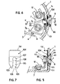
- the spacer is constituted by an elastic blade 10 ⁇ 4 flat as a whole, with a substantially rectangular outline as visible in Figure 7 and in support, by its edges, against the cylindrical inner wall of the distributor housing 1.
- This blade 10 ⁇ 4 can have a bending both in a direction parallel to the generatrices of the housing 1 (see Figure 5), as in the peripheral direction of this housing ( Figure 6).
- the concavity of the blade 10 ⁇ 4 is turned towards the cylindrical internal wall of the housing 1.
- the blade 10 ⁇ 4 has a slot 10 ⁇ 5 (FIG. 7) open at one longitudinal end 10 ⁇ 6 and closed at its other end.
- This slot 10 ⁇ 5 is intended to be crossed, in a direction substantially orthogonal to its mean plane, by the adjusting member 9. More precisely, this slot 10 ⁇ 5 may have the shape of a buttonhole comprising a substantially circular part 10 ⁇ 7 intended for receiving a corresponding part of the adjusting member 9, this part 10 ⁇ 7 communicating, through a throttling zone 10 ⁇ 8, with a part 10 ⁇ 9 which widens in the direction of the end 10 ⁇ 6.
- the throttling zone 10 ⁇ 8 can move aside to allow the corresponding zone of the member 9 to pass, and then tighten so as to elastically trap the outline of the member 9 in the circular part 10 ⁇ 7.
- the blade 10 ⁇ 4, which forms the spacer, then constitutes a kind of fork.
- This slot 10 ⁇ 5 are adapted to cooperate with the groove 97, formed at the periphery of the adjusting member 9, to ensure its axial immobilization, without the need to use a ring or a split ring such as the ring 96 of Figures 3 and 4.
- the axis of the adjusting member 9 is coincident with a radius of a cross section of the housing 1, that is to say that this axis XX passes through the center of a cross section of the housing.
- the parts of the elastic blade 10 ⁇ 4, constituting the spacer, located on either side of the plane passing through the axis of the housing 1 and the axis XX of the member 9 are elastically deformed substantially by the same way.
- An insert 111 (FIG. 6) made of plastic material, or equivalent material, having an elongated opening 112, is advantageously provided in the lumen 7 c of the fixed contact support 7, this lumen 7 c opening, as visible in FIG. 2 , on the side opposite the bottom of the housing 1. It is therefore possible to engage the insert 111, with a closed contour, by this open end.
- the opening 112 is intended to receive the eccentric end 95 of the adjustment means 9.
- the edges 113 of this opening 9, and more precisely the edges parallel to the generatrices of the housing 1, are rounded, as visible in FIG. 6 , so as to allow an angular movement of the eccentric or eccentric finger 95, during the displacement of the support 7.
- the elastic blade 10 ⁇ 4 advantageously comprises, on its edge opposite to that into which the slot 10 ⁇ 5 opens, a return 114, substantially at a right angle, to facilitate gripping and the positioning of this blade 10 ⁇ 4.
- the elastic spacer 93, 10 ⁇ 0 ⁇ or 10 ⁇ 4 exerts an elastic bearing force against the cylindrical internal wall of the housing 1 so that, by reaction, the drive head 98 of the member 9 is applied with a force F, shown in FIG. 5 but also existing in the case of FIGS. 3 and 4, against an external abutment surface linked to the housing 1.
- This increase in the resistance to rotation of the member 9 makes it possible to eliminate, or considerably reduce, untimely misadjustments due to involuntary causes, such as vibrations or other causes, during engine operation.
- the split elastic ring 96 of the Figures 3 and 4 can be deleted, the spacer then also playing the role of this split ring.
- the spacer device according to the invention is simple and quick to set up, and economical.
Landscapes
- Engineering & Computer Science (AREA)
- Chemical & Material Sciences (AREA)
- Combustion & Propulsion (AREA)
- Mechanical Engineering (AREA)
- General Engineering & Computer Science (AREA)
- Ignition Installations For Internal Combustion Engines (AREA)
Applications Claiming Priority (2)
| Application Number | Priority Date | Filing Date | Title |
|---|---|---|---|
| FR8610251A FR2601723B1 (fr) | 1986-07-15 | 1986-07-15 | Distributeur d'allumage pour moteur a combustion interne, en particulier de vehicule automobile |
| FR8610251 | 1986-07-15 |
Publications (2)
| Publication Number | Publication Date |
|---|---|
| EP0253694A1 true EP0253694A1 (de) | 1988-01-20 |
| EP0253694B1 EP0253694B1 (de) | 1991-03-13 |
Family
ID=9337422
Family Applications (1)
| Application Number | Title | Priority Date | Filing Date |
|---|---|---|---|
| EP19870401377 Expired - Lifetime EP0253694B1 (de) | 1986-07-15 | 1987-06-18 | Zündverteiler für Brennkraftmaschinen, besonders von Fahrzeugen |
Country Status (4)
| Country | Link |
|---|---|
| EP (1) | EP0253694B1 (de) |
| DE (1) | DE3768571D1 (de) |
| ES (1) | ES2022397B3 (de) |
| FR (1) | FR2601723B1 (de) |
Citations (7)
| Publication number | Priority date | Publication date | Assignee | Title |
|---|---|---|---|---|
| US2797269A (en) * | 1957-06-25 | buck ctal | ||
| US2835755A (en) * | 1956-10-25 | 1958-05-20 | Filko John | Adjustable contact assembly |
| FR1208839A (fr) * | 1957-11-25 | 1960-02-25 | Gen Motors Corp | Rupteur pour allumeur de moteur à combustion interne |
| FR1566469A (de) * | 1968-03-04 | 1969-05-09 | ||
| US3668339A (en) * | 1966-08-23 | 1972-06-06 | Lucas Industries Ltd | Ignition distributor with a support plate for the contact assembly held in position by zone resilience |
| FR2209407A5 (de) * | 1972-12-04 | 1974-06-28 | Sev Marchal | |
| FR2399553A1 (fr) * | 1977-08-04 | 1979-03-02 | Ducellier & Cie | Distributeur d'allumage pour moteur a combustion interne pour vehicule automobile |
-
1986
- 1986-07-15 FR FR8610251A patent/FR2601723B1/fr not_active Expired
-
1987
- 1987-06-18 DE DE8787401377T patent/DE3768571D1/de not_active Expired - Fee Related
- 1987-06-18 EP EP19870401377 patent/EP0253694B1/de not_active Expired - Lifetime
- 1987-06-18 ES ES87401377T patent/ES2022397B3/es not_active Expired - Lifetime
Patent Citations (7)
| Publication number | Priority date | Publication date | Assignee | Title |
|---|---|---|---|---|
| US2797269A (en) * | 1957-06-25 | buck ctal | ||
| US2835755A (en) * | 1956-10-25 | 1958-05-20 | Filko John | Adjustable contact assembly |
| FR1208839A (fr) * | 1957-11-25 | 1960-02-25 | Gen Motors Corp | Rupteur pour allumeur de moteur à combustion interne |
| US3668339A (en) * | 1966-08-23 | 1972-06-06 | Lucas Industries Ltd | Ignition distributor with a support plate for the contact assembly held in position by zone resilience |
| FR1566469A (de) * | 1968-03-04 | 1969-05-09 | ||
| FR2209407A5 (de) * | 1972-12-04 | 1974-06-28 | Sev Marchal | |
| FR2399553A1 (fr) * | 1977-08-04 | 1979-03-02 | Ducellier & Cie | Distributeur d'allumage pour moteur a combustion interne pour vehicule automobile |
Also Published As
| Publication number | Publication date |
|---|---|
| ES2022397B3 (es) | 1991-12-01 |
| EP0253694B1 (de) | 1991-03-13 |
| DE3768571D1 (de) | 1991-04-18 |
| FR2601723A1 (fr) | 1988-01-22 |
| FR2601723B1 (fr) | 1988-11-10 |
Similar Documents
| Publication | Publication Date | Title |
|---|---|---|
| EP0810944B1 (de) | Schnellspannachse für ein fahrrad | |
| EP0210083B1 (de) | Schnellwechselsystem für Spannbacken an einer Werkzeugmaschine | |
| FR2633990A1 (fr) | Blocage mecanique lineaire avec caracteristique redondante de verrouillage | |
| EP0661190B1 (de) | Verstellbare Sitzarmatur | |
| EP0579549B1 (de) | Scheibenwischeranlage | |
| FR2940813A1 (fr) | Poignee d'ouvrant de vehicule automobile | |
| EP0734496B1 (de) | Automatisch nachstellbare strebe für eine trommelbremse | |
| FR2813847A1 (fr) | Systeme de montage d'un garde-boue equipant une roue directrice d'un vehicule | |
| EP0797718B1 (de) | Provisorischer türanschlag für ein kraftfahrzeugscharnier und vorrichtung um diesen anzubringen | |
| CH690848A5 (fr) | Dispositif de commande de la position d'une partie mobile d'un projecteur de véhicule automobile. | |
| FR2770810A1 (fr) | Mecanisme d'articulation pour siege de vehicule, et siege de vehicule comportant un tel mecanisme | |
| EP0253694A1 (de) | Zündverteiler für Brennkraftmaschinen, besonders von Fahrzeugen | |
| EP0491603B1 (de) | Verbindungsglied zwischen einem Scheibenwischerarm, insbesondere für Kraftfahrzeug | |
| EP1359082B2 (de) | Positionsanpassungseinrichtung einer einstellbaren Kraftfahrzeuglenksäule | |
| EP0995648A1 (de) | Steuersäule-Diebstahlsicherung mit Mittel zur Bolzenverriegelung | |
| FR2637949A1 (fr) | Dispositif de blocage axial d'un organe telescopique tel qu'une colonne de direction de vehicule automobile | |
| EP0597764B1 (de) | Fensterheber für ein Kraftfahrzeug | |
| EP0296961B1 (de) | Befestigungsvorrichtung | |
| EP1637415B1 (de) | Elektrische Vorrichtung für das Verriegeln/Entriegeln einer Lenksäule | |
| WO2009141535A2 (fr) | Montage de roue d'un véhicule automobile au moyen d'un bras pliable entre deux configurations angulaires respectivement contrainte et stable | |
| EP1445168A1 (de) | Vertikale Lagesperrvorrichtung für eine Lenksäule eines Kraftfahrzeuges | |
| FR2720845A1 (fr) | Vis de réglage. | |
| FR2624811A1 (fr) | Antivol de direction a deux penes pivotants pour vehicules automobiles | |
| FR3099089A1 (fr) | Palier et pièce de réglage pour train multi-bras | |
| FR2594392A1 (fr) | Retroviseur exterieur pour vehicule, comportant des moyens d'articulation simplifies |
Legal Events
| Date | Code | Title | Description |
|---|---|---|---|
| PUAI | Public reference made under article 153(3) epc to a published international application that has entered the european phase |
Free format text: ORIGINAL CODE: 0009012 |
|
| AK | Designated contracting states |
Kind code of ref document: A1 Designated state(s): DE ES GB IT |
|
| 17P | Request for examination filed |
Effective date: 19871204 |
|
| 17Q | First examination report despatched |
Effective date: 19900207 |
|
| RAP1 | Party data changed (applicant data changed or rights of an application transferred) |
Owner name: VALEO EQUIPEMENTS ELECTRIQUES MOTEUR |
|
| GRAA | (expected) grant |
Free format text: ORIGINAL CODE: 0009210 |
|
| ITF | It: translation for a ep patent filed | ||
| RAP1 | Party data changed (applicant data changed or rights of an application transferred) |
Owner name: VALEO ELECTRONIQUE |
|
| AK | Designated contracting states |
Kind code of ref document: B1 Designated state(s): DE ES GB IT |
|
| REF | Corresponds to: |
Ref document number: 3768571 Country of ref document: DE Date of ref document: 19910418 |
|
| GBT | Gb: translation of ep patent filed (gb section 77(6)(a)/1977) | ||
| PLBE | No opposition filed within time limit |
Free format text: ORIGINAL CODE: 0009261 |
|
| STAA | Information on the status of an ep patent application or granted ep patent |
Free format text: STATUS: NO OPPOSITION FILED WITHIN TIME LIMIT |
|
| 26N | No opposition filed | ||
| PGFP | Annual fee paid to national office [announced via postgrant information from national office to epo] |
Ref country code: GB Payment date: 19940614 Year of fee payment: 8 |
|
| PGFP | Annual fee paid to national office [announced via postgrant information from national office to epo] |
Ref country code: DE Payment date: 19940629 Year of fee payment: 8 |
|
| PG25 | Lapsed in a contracting state [announced via postgrant information from national office to epo] |
Ref country code: GB Effective date: 19950618 |
|
| GBPC | Gb: european patent ceased through non-payment of renewal fee |
Effective date: 19950618 |
|
| PG25 | Lapsed in a contracting state [announced via postgrant information from national office to epo] |
Ref country code: DE Effective date: 19960301 |
|
| PGFP | Annual fee paid to national office [announced via postgrant information from national office to epo] |
Ref country code: ES Payment date: 20010625 Year of fee payment: 15 |
|
| PG25 | Lapsed in a contracting state [announced via postgrant information from national office to epo] |
Ref country code: ES Free format text: LAPSE BECAUSE OF NON-PAYMENT OF DUE FEES Effective date: 20020619 |
|
| REG | Reference to a national code |
Ref country code: ES Ref legal event code: FD2A Effective date: 20030711 |
|
| PG25 | Lapsed in a contracting state [announced via postgrant information from national office to epo] |
Ref country code: IT Free format text: LAPSE BECAUSE OF NON-PAYMENT OF DUE FEES;WARNING: LAPSES OF ITALIAN PATENTS WITH EFFECTIVE DATE BEFORE 2007 MAY HAVE OCCURRED AT ANY TIME BEFORE 2007. THE CORRECT EFFECTIVE DATE MAY BE DIFFERENT FROM THE ONE RECORDED. Effective date: 20050618 |