EP0253726A1 - Vorrichtung zum Ausheben von Gräben mit Fräsern - Google Patents
Vorrichtung zum Ausheben von Gräben mit Fräsern Download PDFInfo
- Publication number
- EP0253726A1 EP0253726A1 EP87401642A EP87401642A EP0253726A1 EP 0253726 A1 EP0253726 A1 EP 0253726A1 EP 87401642 A EP87401642 A EP 87401642A EP 87401642 A EP87401642 A EP 87401642A EP 0253726 A1 EP0253726 A1 EP 0253726A1
- Authority
- EP
- European Patent Office
- Prior art keywords
- drums
- core
- tools
- machine according
- axes
- Prior art date
- Legal status (The legal status is an assumption and is not a legal conclusion. Google has not performed a legal analysis and makes no representation as to the accuracy of the status listed.)
- Granted
Links
- 239000002689 soil Substances 0.000 title description 2
- 230000001095 motoneuron effect Effects 0.000 title 1
- 238000003801 milling Methods 0.000 claims description 6
- 241000220223 Fragaria Species 0.000 description 4
- 235000021012 strawberries Nutrition 0.000 description 4
- 239000011435 rock Substances 0.000 description 2
- 229910001208 Crucible steel Inorganic materials 0.000 description 1
- 230000005540 biological transmission Effects 0.000 description 1
- 230000015572 biosynthetic process Effects 0.000 description 1
- 230000005570 vertical transmission Effects 0.000 description 1
Images
Classifications
-
- E—FIXED CONSTRUCTIONS
- E02—HYDRAULIC ENGINEERING; FOUNDATIONS; SOIL SHIFTING
- E02F—DREDGING; SOIL-SHIFTING
- E02F3/00—Dredgers; Soil-shifting machines
- E02F3/04—Dredgers; Soil-shifting machines mechanically-driven
- E02F3/18—Dredgers; Soil-shifting machines mechanically-driven with digging wheels turning round an axis, e.g. bucket-type wheels
- E02F3/20—Dredgers; Soil-shifting machines mechanically-driven with digging wheels turning round an axis, e.g. bucket-type wheels with tools that only loosen the material, i.e. mill-type wheels
- E02F3/205—Dredgers; Soil-shifting machines mechanically-driven with digging wheels turning round an axis, e.g. bucket-type wheels with tools that only loosen the material, i.e. mill-type wheels with a pair of digging wheels, e.g. slotting machines
Definitions
- the present invention relates to machines which make it possible to dig trenches in the ground at great depths, using cylindrical cutters which are arranged at the bottom of the machine and which are driven in rotation to disintegrate the ground.
- These machines of known type generally comprise two identical cutters rotating in opposite directions, each consisting of two half-drums supported by a flat core arranged vertically.
- the cutters can be driven by hydraulic or electric motors located along their axes. They can also be done by mechanical devices such as shafts with gearboxes or chains, using motors which are located above the cutters in the body of the machine.
- the core must be able to withstand considerable efforts, because it is necessary to apply a significant torque to the strawberries in order to be able to disintegrate soils made up of rocks and there is, moreover, at the strawberries very significant vibrations which are affect the soul.
- the core must be as strong a piece as possible. It is most often made of cast steel with high mechanical characteristics.
- This step which is thus brought to support a part of the weight of the machine normally breaks by buckling and this all the more easily as the core has a thinner thickness.
- the present invention provides a particularly simple and effective solution to this problem.
- the subject of the present invention is a machine for digging trenches in the ground using cutters, of the type in which two half-drums carrying milling tools are supported by a flat core arranged vertically, characterized in that the axes of the two half-drums are slightly inclined downward away from the plane of the core.
- the axes of the half-drums can be inclined, for example from 1 to 10 degrees relative to the horizontal.
- the tools which are located on the half-drums in the vicinity of the core can work on the lower part of the machine, in the immediate vicinity of one another, eliminating the step or by leaving only a step whose thickness is sufficiently small so that its rupture under the action of the lower part of the core does not raise any difficulties.
- the tools arranged at the external periphery of the half-drums are offset towards the outside so that, when these tools are in the lower part of the half-drums, they break up the ground over a width which corresponds substantially to the width occupied at their upper part by the two half-drums.
- the ends of the milling tools arranged on each half-drum are located on a truncated cone whose generatrices have the same inclination as that of the axes of the half-drums, so that the vertices of these tools are located on a substantially horizontal line when they are at the bottom of the drums.
- the core can be produced with a vertical trapezoidal section which makes it possible to give it the mechanical solidity which is necessary for the transmission of very large forces to the half-drums.
- the two half-drums can be driven using a motor whose casing is made integral with the core and which is provided with a hollow grooved axis inside which engages a grooved shaft which rotates each of the half-drums, for example also by means of grooves.
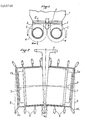
- FIG. 1 There is diagrammatically shown in FIG. 1 the lower part of the body 1 of the machine as well as the two drums 2 which are constituted by half-drums secured on either side of the flat webs 3.
- the outline of the tools 4 placed on the drums 2 has also been represented schematically by dashed lines.
- the drums 2 rotate in opposite directions, as indicated by the arrows, so as to bring between them the debris torn from the ground which are eliminated by the suction nozzle 5 of a pump not shown.
- Figure 2 shows a section along II-II of an embodiment of the invention, the core 3 which has a trapezoidal section and which is therefore much thicker at its upper part than its lower part.
- the core 3 is provided with the plate 6 which allows it to be securely fastened to the lower part of the body of the machine.
- the half-drums 2a and 2b which are rotated around the axes 7 which are inclined downward from the core relative to the horizontal line 8 perpendicular to the median plane of the soul.
- the axes of the half-drums are inclined from 1 to 10 degrees, the diameter of the cutter being, for example, from 120 to 160 cm.
- 2a half drums and 2b are provided on their periphery with conventional tools 4, 4a and 4b.
- the tools 4 b which are located on the external periphery of the half-drums 2 a and 2 b , are offset towards the outside up to a vertical line 9, so as to be at their lower part substantially in line with the external edges of the upper part of the 2a half-drums.
- the tools 4, 4a and 4b digging at the bottom of the machine a trench which corresponds to the maximum width of the drum, given the inclination of the axes 7, corresponds to that of the portion upper half-drums 2a and 2 b .
- the tools 4, 4a and 4b are substantially aligned along a horizontal line so as to ensure a regular size of the trench.
- the half-drums 2a and 2b can be rotated in any way.
- They can for example be driven using two hydraulic motors powered by pipes arranged in the thickness of the core, motors which are coaxial with the half-drums.
- a single motor with a horizontal axis, arranged symmetrically with respect to the core 3 and the axis of which can be connected to the inclined axes of the two half-drums by articulated devices of any type.
- a motor comprising a hollow grooved axis which is connected by one or two grooved shafts to the two half-drums, the play existing at the level of the grooves making it possible to ensure angular catching up between the axes half-drums and that of the engine.
Landscapes
- Engineering & Computer Science (AREA)
- Mechanical Engineering (AREA)
- Mining & Mineral Resources (AREA)
- Civil Engineering (AREA)
- General Engineering & Computer Science (AREA)
- Structural Engineering (AREA)
- Soil Working Implements (AREA)
- Pit Excavations, Shoring, Fill Or Stabilisation Of Slopes (AREA)
- Processing Of Stones Or Stones Resemblance Materials (AREA)
- Superconductors And Manufacturing Methods Therefor (AREA)
- Crushing And Grinding (AREA)
- Bulkheads Adapted To Foundation Construction (AREA)
- Extrusion Moulding Of Plastics Or The Like (AREA)
- Mechanical Treatment Of Semiconductor (AREA)
- Photoreceptors In Electrophotography (AREA)
Priority Applications (1)
| Application Number | Priority Date | Filing Date | Title |
|---|---|---|---|
| AT87401642T ATE55792T1 (de) | 1986-07-15 | 1987-07-10 | Vorrichtung zum ausheben von graeben mit fraesern. |
Applications Claiming Priority (2)
| Application Number | Priority Date | Filing Date | Title |
|---|---|---|---|
| FR8610287 | 1986-07-15 | ||
| FR8610287A FR2601708B1 (fr) | 1986-07-15 | 1986-07-15 | Engin pour creuser des tranchees dans le sol a l'aide de fraises |
Publications (2)
| Publication Number | Publication Date |
|---|---|
| EP0253726A1 true EP0253726A1 (de) | 1988-01-20 |
| EP0253726B1 EP0253726B1 (de) | 1990-08-22 |
Family
ID=9337436
Family Applications (1)
| Application Number | Title | Priority Date | Filing Date |
|---|---|---|---|
| EP87401642A Expired - Lifetime EP0253726B1 (de) | 1986-07-15 | 1987-07-10 | Vorrichtung zum Ausheben von Gräben mit Fräsern |
Country Status (8)
| Country | Link |
|---|---|
| EP (1) | EP0253726B1 (de) |
| JP (1) | JPS6322929A (de) |
| AT (1) | ATE55792T1 (de) |
| CY (1) | CY1698A (de) |
| DE (2) | DE3764423D1 (de) |
| FR (1) | FR2601708B1 (de) |
| HK (1) | HK76593A (de) |
| SG (1) | SG18793G (de) |
Cited By (6)
| Publication number | Priority date | Publication date | Assignee | Title |
|---|---|---|---|---|
| US4834197A (en) * | 1987-05-13 | 1989-05-30 | Bauer Spezialtiefbau Gmbh | Trench cutter |
| DE19754399A1 (de) * | 1997-12-09 | 1999-06-17 | Juergen Posch | Vorrichtung zur Bearbeitung einer länglichen Vertiefung im Erdreich |
| EP1350893A1 (de) * | 2002-04-05 | 2003-10-08 | Spie Fondations | Fräsrad und Schlitzwandfräse umfassend mindestens zwei Fräsräder |
| KR100497031B1 (ko) * | 1996-08-28 | 2005-10-04 | 꽁빠니 뒤 솔 | 지면에서깊은도랑을굴착하는장치와상기장치에의해도랑을굴착하는방법 |
| EP3556942A1 (de) * | 2018-04-18 | 2019-10-23 | BAUER Maschinen GmbH | Schlitzwandfräse und verfahren zum erstellen eines frässchlitzes im boden |
| EP3688234A1 (de) * | 2017-09-25 | 2020-08-05 | Soletanche Freyssinet | Bohrmaschine zur bildung eines nichtgeradlinigen grabens |
Families Citing this family (1)
| Publication number | Priority date | Publication date | Assignee | Title |
|---|---|---|---|---|
| DE29808307U1 (de) | 1998-05-11 | 1998-08-20 | Möbius, Andreas, Prof. Dr.rer.nat., 41472 Neuss | Vorrichtung zum gerichteten Einblasen von Luft, anderen Gasen oder Dämpfen unter gleichzeitiger Flüssigkeitsumwälzung |
Citations (5)
| Publication number | Priority date | Publication date | Assignee | Title |
|---|---|---|---|---|
| DE960392C (de) * | 1954-02-27 | 1957-03-21 | Erwin Baas | Vorrichtung zur Herstellung neuer bzw. zum Reinigen bestehender Graeben |
| FR1429215A (fr) * | 1965-04-09 | 1966-02-18 | Socomec Sa | Machine à creuser des tranchées, à lames tournantes s'enfonçant dans le terrain, particulièrement pour l'agriculture |
| US3510970A (en) * | 1967-03-02 | 1970-05-12 | Pavel Mikhailovich Mikhailov | Excavator with inclined bucket wheels attached to a working unit which is horizontally maintained |
| DE1634262B1 (de) * | 1966-04-09 | 1970-09-24 | Bade & Co Gmbh | Fraeswerkzeug zum Herstellen von Schlitzen fuer Schlitzwaende |
| DE2362425A1 (de) * | 1972-12-14 | 1975-01-30 | Hydrosol | Vorrichtung zum herstellen von bohrungen im erdreich |
Family Cites Families (1)
| Publication number | Priority date | Publication date | Assignee | Title |
|---|---|---|---|---|
| JPS586931U (ja) * | 1981-07-04 | 1983-01-17 | 株式会社ボッシュオートモーティブ システム | 大気圧補正装置付の内燃機関用遠心力調速機のアネコンレバ− |
-
1986
- 1986-07-15 FR FR8610287A patent/FR2601708B1/fr not_active Expired
-
1987
- 1987-07-10 AT AT87401642T patent/ATE55792T1/de not_active IP Right Cessation
- 1987-07-10 DE DE8787401642T patent/DE3764423D1/de not_active Expired - Fee Related
- 1987-07-10 DE DE198787401642T patent/DE253726T1/de active Pending
- 1987-07-10 EP EP87401642A patent/EP0253726B1/de not_active Expired - Lifetime
- 1987-07-14 JP JP62175801A patent/JPS6322929A/ja active Pending
-
1993
- 1993-02-19 SG SG187/93A patent/SG18793G/en unknown
- 1993-07-29 HK HK765/93A patent/HK76593A/xx unknown
-
1994
- 1994-01-14 CY CY169894A patent/CY1698A/xx unknown
Patent Citations (5)
| Publication number | Priority date | Publication date | Assignee | Title |
|---|---|---|---|---|
| DE960392C (de) * | 1954-02-27 | 1957-03-21 | Erwin Baas | Vorrichtung zur Herstellung neuer bzw. zum Reinigen bestehender Graeben |
| FR1429215A (fr) * | 1965-04-09 | 1966-02-18 | Socomec Sa | Machine à creuser des tranchées, à lames tournantes s'enfonçant dans le terrain, particulièrement pour l'agriculture |
| DE1634262B1 (de) * | 1966-04-09 | 1970-09-24 | Bade & Co Gmbh | Fraeswerkzeug zum Herstellen von Schlitzen fuer Schlitzwaende |
| US3510970A (en) * | 1967-03-02 | 1970-05-12 | Pavel Mikhailovich Mikhailov | Excavator with inclined bucket wheels attached to a working unit which is horizontally maintained |
| DE2362425A1 (de) * | 1972-12-14 | 1975-01-30 | Hydrosol | Vorrichtung zum herstellen von bohrungen im erdreich |
Cited By (10)
| Publication number | Priority date | Publication date | Assignee | Title |
|---|---|---|---|---|
| US4834197A (en) * | 1987-05-13 | 1989-05-30 | Bauer Spezialtiefbau Gmbh | Trench cutter |
| KR100497031B1 (ko) * | 1996-08-28 | 2005-10-04 | 꽁빠니 뒤 솔 | 지면에서깊은도랑을굴착하는장치와상기장치에의해도랑을굴착하는방법 |
| DE19754399A1 (de) * | 1997-12-09 | 1999-06-17 | Juergen Posch | Vorrichtung zur Bearbeitung einer länglichen Vertiefung im Erdreich |
| US6085446A (en) * | 1997-12-09 | 2000-07-11 | Posch; Juergen | Device for excavating an elongated depression in soil |
| DE19754399C2 (de) * | 1997-12-09 | 2002-04-25 | Juergen Posch | Vorrichtung zur Bearbeitung einer länglichen Vertiefung im Erdreich |
| EP1350893A1 (de) * | 2002-04-05 | 2003-10-08 | Spie Fondations | Fräsrad und Schlitzwandfräse umfassend mindestens zwei Fräsräder |
| EP3688234A1 (de) * | 2017-09-25 | 2020-08-05 | Soletanche Freyssinet | Bohrmaschine zur bildung eines nichtgeradlinigen grabens |
| US11519153B2 (en) | 2017-09-25 | 2022-12-06 | Soletanche Freyssinet | Boring machine for producing a non-rectilinear trench |
| EP3556942A1 (de) * | 2018-04-18 | 2019-10-23 | BAUER Maschinen GmbH | Schlitzwandfräse und verfahren zum erstellen eines frässchlitzes im boden |
| US11286637B2 (en) | 2018-04-18 | 2022-03-29 | Bauer Maschinen Gmbh | Trench cutter and method for producing a cut trench in the soil |
Also Published As
| Publication number | Publication date |
|---|---|
| JPS6322929A (ja) | 1988-01-30 |
| FR2601708A1 (fr) | 1988-01-22 |
| HK76593A (en) | 1993-08-06 |
| DE253726T1 (de) | 1988-09-01 |
| FR2601708B1 (fr) | 1989-10-27 |
| CY1698A (en) | 1994-01-14 |
| DE3764423D1 (de) | 1990-09-27 |
| ATE55792T1 (de) | 1990-09-15 |
| SG18793G (en) | 1993-04-16 |
| EP0253726B1 (de) | 1990-08-22 |
Similar Documents
| Publication | Publication Date | Title |
|---|---|---|
| EP2002061B1 (de) | Bohrwerkzeug | |
| FR2578876A1 (fr) | Excavatrice de tranchee | |
| EP1437445A1 (de) | Frästrommel für die Herstellung von senkrechten Schlitzen | |
| EP0253726B1 (de) | Vorrichtung zum Ausheben von Gräben mit Fräsern | |
| EP1975323B1 (de) | Schneidkopf für eine Bodenschneidemaschine mit rotierenden Fräsen | |
| EP0263762B1 (de) | Fräsvorrichtung zum Ausheben von Gräben im Boden | |
| FR2981682A1 (fr) | Dispositif de forage de grand diametre | |
| EP0258122B1 (de) | Fräsvorrichtung zum Ausheben von Graben im Boden | |
| EP0826835B1 (de) | Baggergerät zum Graben von Tiefgräben | |
| FR2574847A1 (fr) | Dispositif pour effectuer des forages circulaires de grand diametre dans le sol | |
| EP0592325B1 (de) | Baggergerät zum Graben von Tiefgräben mit auf einem Rahmen montierten Frästrommeln | |
| EP0592326B1 (de) | Baggergerät zum Graben von Tiefgräben mit Frästrommeln | |
| EP0353152B1 (de) | Vorrichtung zum Abführen von Erdreich für die Herstellung von Tiefgräben | |
| EP0378485B1 (de) | Vorrichtung zum Befestigen von Frästrommeln an einem Baggergerät,das für das Ausheben von Gräben im Boden bestimmt ist | |
| EP0533559B1 (de) | Schalengreiferbagger | |
| CA1296320C (fr) | Procede d'exploitation des mines et appareil pour la mise en oeuvre de ce procede | |
| FR2566024A1 (fr) | Dispositif pour ouvrir des tranchees etroites | |
| CA1273965A (fr) | Procede et dispositif de creusement de puits | |
| FR2525252A1 (fr) | Engin de travaux publics pour le remblaiement et/ou le compactage d'une tranchee | |
| CA2492937C (fr) | Outil d'excavation pour pelleteuse hydraulique | |
| FR2726018A1 (fr) | Fraise avec palier a roulement, adaptee pour l'execution d'excavations | |
| FR2565290A1 (fr) | Procede et dispositif de creusement de puits | |
| FR2696765A1 (fr) | Appareil pour réaliser des pieux dans le sol par mélange in situ d'un liant avec le terrain. | |
| FR3071535B1 (fr) | Machine de forage pour la realisation d'une tranchee non rectiligne | |
| WO2025153479A1 (fr) | Tête de coupe pour machine d'excavation, et machine d'excavation correspondante |
Legal Events
| Date | Code | Title | Description |
|---|---|---|---|
| PUAI | Public reference made under article 153(3) epc to a published international application that has entered the european phase |
Free format text: ORIGINAL CODE: 0009012 |
|
| AK | Designated contracting states |
Kind code of ref document: A1 Designated state(s): AT BE DE GB IT |
|
| ITCL | It: translation for ep claims filed |
Representative=s name: MODIANO & ASSOCIATI S.R.L. |
|
| 17P | Request for examination filed |
Effective date: 19880317 |
|
| GBC | Gb: translation of claims filed (gb section 78(7)/1977) | ||
| TCAT | At: translation of patent claims filed | ||
| DET | De: translation of patent claims | ||
| 17Q | First examination report despatched |
Effective date: 19890519 |
|
| GRAA | (expected) grant |
Free format text: ORIGINAL CODE: 0009210 |
|
| AK | Designated contracting states |
Kind code of ref document: B1 Designated state(s): AT BE DE GB IT |
|
| REF | Corresponds to: |
Ref document number: 55792 Country of ref document: AT Date of ref document: 19900915 Kind code of ref document: T |
|
| GBT | Gb: translation of ep patent filed (gb section 77(6)(a)/1977) | ||
| REF | Corresponds to: |
Ref document number: 3764423 Country of ref document: DE Date of ref document: 19900927 |
|
| ITF | It: translation for a ep patent filed | ||
| PLBE | No opposition filed within time limit |
Free format text: ORIGINAL CODE: 0009261 |
|
| STAA | Information on the status of an ep patent application or granted ep patent |
Free format text: STATUS: NO OPPOSITION FILED WITHIN TIME LIMIT |
|
| ITTA | It: last paid annual fee | ||
| 26N | No opposition filed | ||
| PGFP | Annual fee paid to national office [announced via postgrant information from national office to epo] |
Ref country code: GB Payment date: 19930618 Year of fee payment: 7 |
|
| PGFP | Annual fee paid to national office [announced via postgrant information from national office to epo] |
Ref country code: BE Payment date: 19930709 Year of fee payment: 7 |
|
| PGFP | Annual fee paid to national office [announced via postgrant information from national office to epo] |
Ref country code: AT Payment date: 19930720 Year of fee payment: 7 |
|
| PG25 | Lapsed in a contracting state [announced via postgrant information from national office to epo] |
Ref country code: GB Effective date: 19940710 Ref country code: AT Effective date: 19940710 |
|
| PG25 | Lapsed in a contracting state [announced via postgrant information from national office to epo] |
Ref country code: BE Effective date: 19940731 |
|
| BERE | Be: lapsed |
Owner name: SOLETANCHE Effective date: 19940731 |
|
| GBPC | Gb: european patent ceased through non-payment of renewal fee |
Effective date: 19940710 |
|
| PGFP | Annual fee paid to national office [announced via postgrant information from national office to epo] |
Ref country code: DE Payment date: 20040702 Year of fee payment: 18 |
|
| PG25 | Lapsed in a contracting state [announced via postgrant information from national office to epo] |
Ref country code: IT Free format text: LAPSE BECAUSE OF NON-PAYMENT OF DUE FEES;WARNING: LAPSES OF ITALIAN PATENTS WITH EFFECTIVE DATE BEFORE 2007 MAY HAVE OCCURRED AT ANY TIME BEFORE 2007. THE CORRECT EFFECTIVE DATE MAY BE DIFFERENT FROM THE ONE RECORDED. Effective date: 20050710 |
|
| PG25 | Lapsed in a contracting state [announced via postgrant information from national office to epo] |
Ref country code: DE Free format text: LAPSE BECAUSE OF NON-PAYMENT OF DUE FEES Effective date: 20060201 |