EP0253787A2 - Methode zur Regelung von bürstenlosen Gleichstrommotoren und Gerät zur Durchführung dieser Methode - Google Patents
Methode zur Regelung von bürstenlosen Gleichstrommotoren und Gerät zur Durchführung dieser Methode Download PDFInfo
- Publication number
- EP0253787A2 EP0253787A2 EP87850193A EP87850193A EP0253787A2 EP 0253787 A2 EP0253787 A2 EP 0253787A2 EP 87850193 A EP87850193 A EP 87850193A EP 87850193 A EP87850193 A EP 87850193A EP 0253787 A2 EP0253787 A2 EP 0253787A2
- Authority
- EP
- European Patent Office
- Prior art keywords
- pulse
- current state
- maximum current
- minimum
- motor
- Prior art date
- Legal status (The legal status is an assumption and is not a legal conclusion. Google has not performed a legal analysis and makes no representation as to the accuracy of the status listed.)
- Withdrawn
Links
Images


Classifications
-
- H—ELECTRICITY
- H02—GENERATION; CONVERSION OR DISTRIBUTION OF ELECTRIC POWER
- H02P—CONTROL OR REGULATION OF ELECTRIC MOTORS, ELECTRIC GENERATORS OR DYNAMO-ELECTRIC CONVERTERS; CONTROLLING TRANSFORMERS, REACTORS OR CHOKE COILS
- H02P6/00—Arrangements for controlling synchronous motors or other dynamo-electric motors using electronic commutation dependent on the rotor position; Electronic commutators therefor
- H02P6/06—Arrangements for speed regulation of a single motor wherein the motor speed is measured and compared with a given physical value so as to adjust the motor speed
Definitions
- the present invention relates to a method for controlling variable reluctance-type brushless d.c. motors and apparatus for carrying out the method. More particularly, the invention pertains to the current limitation normally applied in methods and apparatus intended for the operation and control of brushless d.c. motors.
- a brushless d.c. motor having at least two phase windings is operated by driving current pulses through the phase windings over a time interval which is contingent on rotation of the rotor.
- the motor can be controlled through variation of the effective value of the current pulses.
- it is necessary to sense the motor current and to effect control in a manner such as to ensure that the current does not become excessively high. Examples of known methods and arrangements for controlling brushless d.c. motors that have at least two phases are documented in GB 2,126,025, IEE PROC, Vol. 128, Pt. B. No. 2, March 1981, pages 126-136, and technical information concerning drive systems from UNITRODE, entitled "Linear Integrated Circuits", and the designation UC 3620 series.
- each of the driving pulses normally comprising two or more regularly occurring pulse-width-modulated part-pulses.
- the pulse frequency of the part-pulses is often fixed, i.e. independent of motor speed.
- no part-pulse is delivered to the power unit until a pre-determined time period has lapsed from the time of detecting the occurrence of a maximum current state.
- no part-pulse is delivered to the power unit until the motor current has fallen to an established level lower than the level at which the maximum current state was detected.
- the difference between the levels and the pre-determined time, respectively, is then generally determined on the basis of the highest frequency at which certain semiconductor components in the power unit can operate.
- Other current limiting methods are known to the art, inter alia where actual pulse width-modulating of part-pulses in the driving pulses is not included.
- one object of the present invention is to provide a method and an arrangement with which these drawbacks are not encountered.
- Another object of this invention is to provide a method and arrangement with which brushless motors of the kind in question can be controlled in a flexible, simple and inexpensive manner.
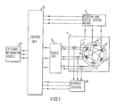
- Fig. 1 is a greatly simplified block schematic of a motor control system according to the invention.
- the purpose of Fig. 1 is not to illustrate in detail the total construction of a complete motor-control system, but rather to illustrate roughly how particularly essential components of such a system co-act with one another. Consequently, the main purpose of the arrows drawn between the various blocks of the block schematic is to illustrate the flow of information and pulses between these components, rather than to denote the number of electric conductors used to interconnect the components in practice.
- the block schematic relates to a three-phase variable reluctance motor, three parallel arrows, conductors or lines have been used in the majority of cases, in order to obtain a lucid and clear block schematic. It will be understood that the number of conductors between the conductors may, in reality, be greater or smaller than that illustrated.
- the brushless d.c. motor 1 which in the block schematic has the form of a variable reluctance motor, has three phase windings 2 ⁇ , 2 ⁇ , 3 ⁇ , 3 ⁇ and 4 ⁇ , 4 ⁇ .
- the motor is driven from a power unit 5, which sends current pulses to the phase windings.
- the power unit may, for instance, have double power stages, in a known manner, with transistors (not shown) for each phase.
- the power source incorporates an energy source, such as an accumulator or battery for example.
- the frequency and duration of the current pulses delivered to the phase windings from the power unit are controlled with driving pulses delivered to the power unit from a control unit 6.
- the control unit receives from sensors 7 information concerning the rotational angle of the rotor and the speed of the motor. For example, three sensors of a known kind may be arranged in connection with respective phases in a manner known per se. As an alternative it is also possible to have a rotation sensing means 7 which derives the rotor speed by monitoring motor signals in a way known in the art and not further described because it is not a part of the actual invention.
- the control unit also received information relating to motor current, i.e. the currents i supplied to the phase windings of the motor, with the aid of sensors 8.
- the sensors 8 may also comprise three known sensors, and are arranged in connection with the power stage of the control unit of the lines to the phase windings, in a manner known per se.
- the control unit also receives control information from an external information source 9.
- the external information source may, for instance, be constructed to deliver information concerning a set point value relating to motor speed.
- the control unit 6 is constructed to vary the driving pulse parameters in response to information received from the sensors and from the external information source, for example to vary the frequency, effective value and phase position of the driving pulses in relation to the angular position of rotor rotation, in order to achieve a desired motor speed at different operating conditions.
- Certain limitations are found in this regard.
- One normal and important limitation is that the momentary current in the power stages must be limited, which means that the motor current must not be too high.
- the invention is primarily directed towards the manner in which the driving pulses are influenced when a maximum current state is sensed in respect of the motor current, i.e. at least one current i supplied to a phase winding or to a power stage has reached its maximum permitted value, at least temporarily, it being assumed here that each driving pulse normally comprises at least two regularly occurring pulse-width modulated part-pulses.
- the uppermost diagram 2A illustrates two successive driving pulses delivered to the same phase, each of which driving pulses comprises a multiple of regularly occurring part-pulses P1, P2, P3 in the case of the first driving pulse, and P4, P5, P6 in the case of the other.
- the control unit will supply the phase-winding power stages in the power unit with driving pulses which, in principle, are similar to those aforementioned but which are displaced in time in relation to one another (60° for a three-phase motor).
- the upper pulse diagram of Fig. 2A illustrates the configuration of a pulse sequence in the absence of sensing a maximum current state.
- the intermediate pulse diagram of Fig. 2B illustrates how a detected maximum current state, detected at time points ⁇ 1- ⁇ 5 marked on the time axis, influences the pulses sent to the power unit from the control unit when practising a known technique.
- the lowermost pulse diagram of Fig. 2C illustrates how the detected maximum current states in the system according to the invention influence the pulses sent to the power unit 5 from the control unit 6.
- the first driving pulse in the uppermost diagram 2A of Fig. 2 consists of three part-pulses P1, P2 and P3, whereas the second driving pulse consists of three part-pulses P4, P5 and P6.
- the part-pulses all have the same width and successive part-pulses of a driving pulse and are spaced at equal distances apart.
- Modulation is maximum or almost maximum, i.e. the space between successive part-pulses is smaller in comparison with the width of each part-pulse.
- the motor also runs at a relatively high speed, which is made evident by the fact that the number of part-pulses with each driving pulse is low.
- the generation of part-pulses is interrupted, or the supply of part-pulses is blocked, for a pre-determined length of time, from that moment of detecting the occurrence of a maximum current state. For the sake of clarity, this time period should have been made twice as great as the distance between successive part pulses in Fig. 2B.
- the pulse diagram of Fig. 2C shows clearly that all part-pulses P1-P5, from the moment of detecting the occurrence of a maximum current state, are shortened by the whole of their normal residual part, according to the uppermost curve. This shortening of the part-pulses takes place irrespective of whether the maximum current state is detected at the midway point of a pulse or at the end thereof, and irrespective of whether the maximum current state ceases before respective part- pulses are due to terminate.
- Each subsequent part-pulse after the detection of a maximum current state is permitted to commence at a normal time point, provided that the maximum current state detected during the preceding part-pulse is not still occurrent at the time when the next part-pulse is due.
- a dynamic relationship prevails between the occurrence of a maximum current state and such operational parameters as motor speed, motor load and the modulation of the pulses.
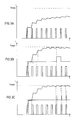
- Figs. 3A-3C, 4A-4C, 5A-5C an attempt has been made, with the aid of an idealized pulse diagram, to illustrate a few operational conditions in the case of a variable reluctance motor, a) a few operational conditions when no maximum current state is detected, Figs. 3A, 4A, 5A, b) a few operational conditions relating to known techniques, Figs. 3B, 4B, 5B, and c) a few operational conditions where control is effected in accordance with the present invention, Figs. 3C, 4C, 5C.
- the pulses shown at the bottom of respective diagrams represent part-pulses during one single operating pulse for one phase.
- the curve which is predominantly uppermost illustrates the motor current in a time sequence.
- the motor speed is comparatively low in Figs. 3A-3C and 4A-4C and comparatively high in Figs. 5A-5C, and hence the time scale is different between these two groups of Figures.
- the curve which presents "spiked" narrow pulses between the current curve and the part-pulses in Figs. 3C, 4C and 5C illustrates the times at which a maximum current state was sensed or detected.
- the curve at a corresponding location with solely one wide pulse in Figs. 3B and 5B and a multiple of wide pulses in Fig. 4B shows the pre-determined times at which part-pulses are not generated or at which the transfer of part-pulses is blocked in accordance with known techniques. All Figs. 3A-3C, 4A-4C, 5A-5C, and also Figs.
- Fig. 3A illustrates a case when the load is moderate and no maximum current state occurs.
- the Figure therefore applies both to a system according to the invention and a system according to known techniques.
- Fig. 3B illustrates the known technique
- Fig. 3C illustrates the present invention when the load is high and a maximum current state is detected.
- the last three part-pulses have been shortened at their trailing edges
- the pulse that is third from the end is shortened at its trailing edge and the penultimate part-pulse is shortened at its leading edge.
- the last part-pulse in Fig. 3B is not influenced by the maximum current state.
- Fig. 4B relates to the known technique and Fig. 4C to the invention when the load is at a maximum and a maximum current state is detected during each part-pulse.
- Modulation of the part-pulses is at maximum during the pulse-width modulation according to Figs. 4B and 4C, such that the part-pulses form a continuous driving pulse which is interrupted solely when a maximum current state is detected.
- the blocking time at maximum current in the case of the system that functions in accordance with the known technique is selected so as not to exceed the working frequency of the power stages. This working frequency also coincides with the frequency of the pulse width modulated part-pulses.
- the frequencies in Figs. 4B and 4C are roughly the same, i.e.
- Fig. 4A illustrates a curve form with a control pulse width that coincides approximately with the obtained pulse width in Figs. 4B and 4C, and where maximum current is not reached. At higher motor speeds, when no maximum current state occurs, the conditions are the same as those experienced with the invention and with known techniques.
- Fig. 5A illustrates one such case in operation.
- Fig. 5B illustrates the known technique when the load has increased above the load in the Fig. 5A illustration. Pulse modulation has also been increased, in order to maintain a preselected or set motor speed, and is in this case at a maximum.
- the power stage When a maximum current state is detected, the power stage is switched off and is held switched off for a given length of time, which is of the same duration as in Figs. 3B and 4B. (The time scales are different in Figs. 3A-3C and Figs. 4A-4C and Figs. 5A-5C.)
- the effective current value, and therewith the motor torque falls and in the operational case illustrated in Fig. 5B is lower than in the operational case illustrated in Fig. 5A, despite higher modulation.
- the motor torque is lower than the load and the set/desired speed cannot be maintained.
- Fig. 5C illustrates the invention when the load and modulation is maximum and the occurrence of a maximum current state is detected during the first two pulses.
- the counter-EMF or back-EMF of the motor is sufficient, in this case, to avoid maximum current during the last pulse.
- the next following part-pulse may also be influenced by this maximum current state.
- the reason for this is that there is a certain delay between the moment at which the power stages are switched off and the moment at which this takes effect, this delay being dictated by reasons of a constructional nature. Consequently, subsequent to switching-off, the current will be slightly higher than the current limit level. At high motor speeds and practically full pulse-width-modulation, or at very low motor speeds and low modulation, this may cause the level of current to remain above the current limit level when the next pulse-width-modulated part-pulse is due to arrive.
- the speed at which this problem can begin to manifest itself depends on the construction of the motor concerned. This speed normally lies roughly at half the maximum speed, although wide variations are found, both in an upward and in a downward direction.
- it is not suitable to control the system by sensing both maximum and minimum current states at low motor speeds with many part-pulses per driving pulse. Neither are the good attributes of the fundamental part of the invention negated by a high counter-EMF at low motor speeds. Consequently, in accordance with this further development of the invention, there is pre-selected a motor speed limit above which the level of minimum current is set.
- the motor speed limit is preferably incorporated during the manufacturing stage or by the motor supplier, although a facility may be incorporated by means of which the motor speed limit can be varied, for instance with the aid of a manually operated control device.
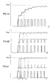
- Fig. 6 illustrates part-pulses and a motor current diagram according to the first embodiment of the further development of the invention.
- Two levels are drawn in the dia gram, namely i max and i min .
- the motor rotates at a high speed. Consequently, there are only a few part-pulses (five in number) in the illustrated embodiment.
- Driving of the motor during the duration of the part-pulses follows the course of a curve whose slope is dependent on time.
- i x dL/dt is the counter-EMF. It will be seen from Fig. 6 that the drive during the first part pulse rises steeply, although this rise decreases gradually during the following part-pulses. The drive during the last part-pulse has a falling curve form. During the third part-pulse a maximum current state is indicated at time point t ö . The sharply falling curve form would continue right down to S1 during the next pulse pause, if detection of a minimum current state did not take place. The current curve now reaches the level i min at time point t u . The next part-pulse is commenced immediately upon detection of the minimum current state.
- the normal part pulse period is thus T, although when an minimum current state is detected, the period in the occurrent part-pulse period is shortened to T A .
- the period time of subsequent periods is not affected.
- An important feature of the further development of the invention is illustrated in the fourth part-pulse period.
- the falling part of the curve 1 passing through the pulse interspace continues through the i min level without the minimum current state being detected. This is because no maximum current state has been detected within the same part-pulse period. Consequently, no minimum current state detection takes place.
- Fig. 7 illustrates another embodiment of the further development according to the invention.
- each part-pulse period T is divided into the pulse interval T1 and the pulse interval T2.
- the duration of each pulse interspace must at least reach the time T2. This is shown for the third pulse period in Fig. 7, where the maximum current state is detected at time point t ⁇ ö .
- the falling part of the curve i ⁇ lies beneath the following pulse pause.
- the duration of the pulse pause has then been shorter than T2, and hence the pulse pause will continue until it reaches T2.
- the next part pulse period then commences.
- Fig. 8 is a block schematic illustrating a preferred embodiment of a system constructed in accordance with the invention.
- certain components of minor importance have been omitted from the Figure, for example the external information source for set-point values and the means for making comparisons between set-points and real values.
- the reference used to identify the components of the Fig. 1 block schematic have been retained followed by a period, or full stop. The reference following the period or full stop denotes the separate unit or component included in the block.
- the "external" input signal to the block schematic is therefore a modulating signal U to the comparator 6.0, this modulating signal deriving from the components omitted from the Figure.
- the comparator is constructed to compare the level of the modulating signal with a ramp or sawtooth signal U s arriving from the sawtooth generator 6.9.
- the sawtooth signal has a steeply rising leading flank and a sloping trailing flank, as will be seen from the waveform diagram drawn in the Figure on the line extending between the generator 6.9 and the comparator 6.0.
- the sawtooth generator is phase-adjusted at appropriate times by pulses arriving on an input s , as described in more detail hereinafter. Such an adjustment has been effected at time point t s .
- the comparator 6.0 generates a first train of pulses which have a high or a low level, depending on whether the level of the modulating signal is higher or lower than the level of the ramp or sawtooth signal.
- the modulating signal U is constant within a driving pulse interval, so that the pulses normally have a constant width within said interval.
- This first pulse train is applied to a first flank sensor 6.1A which is operative in generating a high level pulse of short duration each time the first pulse train passes from a low level to a high level.
- the comparator 6.0 also generates a second pulse train, the level of which is complementary to the level of the first pulse train.
- This second pulse train is applied to a second flank sensor, or flank circuit, 6.1B, which is operative in generating a high level pulse of short duration each time the second pulse train passes from a low level to a high level.
- An OR-gate 6.2 receives the pulses deriving from the second flank sensor and pulses which derive from a third flank sensor 6.1C.
- An SR-type bistable flip-flop 6.3 is arranged to receive on its setting input the pulse arriving from the first flank sensor and to receive on its re-setting input R, via the OR-gate 6.2, the pulses deriving from the second and the third flank sensor 6.1B, 6.1C.
- the bistable flipflop 6.3 will therefore generate on its output a third pulse train, the pulse/time ratio of which will coincide with the pulse/time ratio of the first pulse train deriving from the comparator, provided that no pulses are delivered to the OR-gate 6.2 from the third flank sensor 6.1C.
- the third flank sensor 6.1C generates a high level pulse of short duration each time the sensor unit 8 begins to generate a signal that indicates the occurrence of a maximum current state. Detection of a maximum current state while the pulse train from the bistable flip-flop has a high level therefore causes the flip-flop 6.3 to be restored, or re-set, and the level becomes low. The pulse train will not then return to a high level until a high level pulse from the first flank sensor appears on the setting input S of the flip-flop 6.3. Consequently, the high level pulses from the bistable flip-flop 6.3 are shortened by the whole of their normally remaining part, irrespective of whether the maximum current state ceases or not during the time that this normally residual part of the pulses should have been present.
- the signal from the sensors 8 indicating the occurrence of a maximum current state are also applied to an inverting input of an AND-gate 6.4.
- the other gate-input, which is not inverting, is supplied with the third pulse train from the flip-flop 6.3.
- the AND-gate 6.4 transfers the pulse train deriving from the flip-flop 6.3 to an input of first logic gates 6.5A, but only in the absence of a signal from the sensors 8 indicating that a maximum current state has occurred.
- the sensing unit 7 monitoring the rotational position of the rotor transmit rotor position signals to a phase compensator 6.7, which is turn sends phase-compensated rotor position signals to logic gates 6.5B and to a synchronizing flank sensor 6.8.
- the synchronizing flank sensor 6.8 generates synchronizing signals which are applied to the sawtooth generator 6.9 for intermittent synchronization, once for each driving pulse, of the phase position of the ramp or sawtooth signal from the sawtooth generator 6.9 with the rotational position of the rotor. This results in synchronization of the part-pulses with the driving pulses.
- the purpose of the phase compensator 6.7 in this case is to render the phase position of the driving pulses in relation to the rotor dependent on rotor speed, c.f. GB 2 126 026.
- the frequency of the sawtooth generator 6.9 of the Fig. 8 embodiment i.e. the duration of the individual ramp or sawtooth signals in time, is not dependent on the speed of the rotor.
- the circuit illustrated in Fig. 8 is complemented with an SR-type bistable flip-flop 6.10, an AND-gate 6.11, a flank sensor 6.12, and an OR-gate 6.13.
- the signal deriving from the flank sensor 6.1C is coupled to the setting input of the flip-flop 6.10, and the signal from the flank sensor 6.1A is coupled to the re-setting or restoring input of said flip-flop.
- the flip-flop 6.10 is, in this way, set each time that a maximum current state is detected and restored at the beginning of each new part-pulse.
- the current sensor unit 8 is constructed to apply a pulse on a second input, when the motor current reaches a pre-determined minimum value which the current must not fall below during the same part-pulse period as that in which a maximum current state has been detected.
- the rotor position sensing unit 7 has an output which is connected to a rotation speed counter and threshold value circuit 6.14 which calculates the speed and produces a logic "l"-signal on its output when the rotation speed exceeds a pre-determined value.
- This value can be set during the manufacturing stage, or provisions can be made which enable the value to be adjusted by the user.
- the respective outputs of the flip-flop 6.10, the current sensing unit 8, and the circuit 6.14 are each connected to a respective input of the AND-gate 6.11.
- the AND-gate will thus produce a pulse if a minimum current state is detected during the same part-pulse period as that in which a maximum current state has been detected.
- the output of the AND-gate 6.11 is connected to the flank sensor 6.12.
- the spiked output signal driving from the flank sensor is fed to the sawtooth generator 6.9, via the OR-gate 6.13.
- the output of the syncflank sensor 6.8 is connected to the other input of the OR-gate 6.13.
- the sawtooth generator 6.9 reacts in the same manner for the signals from the flank sensors 6.8 and 6.12 and immediately commences a new period, as illustrated at time point t s .
- the arrangement illustrated in Fig. 8 is provided with an emergency stop facility which, upon detection of an exceptionally high excess current or current surge, will permanently switch off both power stages to respective phases.
- the sensor unit 8 is constructed to generate an emergency stop signal on a third output coupled to the input of a latch circuit 6.6, upon detection of a current which is considerably higher than that required to constitute the aforesaid maximum current state.
- the latch circuit 6.6 Upon receipt of this signal, the latch circuit 6.6 sends a switch-off signal to the second logic gates 6.5B.
- the latch circuit is also arranged to continue to send the switch-off signal even if the sensor unit 8 ceases to generate the emergency stop signal.
- the second logic gates 6.5B are coupled to the one power stages 5.A of the phases, via the first logic gates 6.5A, and also directly to the second power stages 5.B of said phases. Consequently, when an emergency stop signal is generated, both power stages 5.A and 5.B are permanently switched-off, whereas when a maximum current signal is generated only the one power stage 5.A is switched-off, temporarily. Consequently, in the Fig. 8 embodiment the part-pulses discussed above with reference to Figs. 2-10 are transmitted from the first logic gates 6.5A to the first power stages 5.A.
- the pulse-width-modulation is effected mainly by the comparator 6.0. Shortening of the part-pulses is effected by the flip-flop 6.3, and elimination of solitary part-pulses is effected by the logic circuit 6.4.
- the described embodiments can be complemented with embodiments and devices which will ensure that the given time point from which respective part-pulses are shortened coincides essentially with either the time point at which respective maximum current states are detected, or the later point in time at which the duration of respective part-pulses exceeds a pre-de termined minimum value.
- This pulse extending unit may have various different forms.
- this unit is shown, by way of example, to include a monostable flip-flop 6.16 which is fed on the input thereof with the signal present on the relevant output of the logic gates 6.5A.
- the activation time of the monostable flip-flop 6.16 is equal to said minimum value of the duration of the part-pulses.
- the output of the flip-flop 6.16 and the relevant output of the logic gates 6.5A are each coupled to a respective input of an OR-gate 6.17.
- the output of this OR-gate 6.17 is coupled to the one input of the one power stage 5.A.
- Fig. 8 incorporates conventional circuits. It will be readily understood that modern technology enables the control to be accomplished equally as well with, e.g., the aid of a microprocessor which is programmed to simulate the circuitry of Fig. 8.
- the control shown in Fig. 7 has not been illustrated with the aid of coupling circuitry. This is because the control illustrated in this Figure cannot be achieved readily with conventional circuitry techniques, i.e. with the aid of pure hardware.
- the control can, on the other hand, be readily accomplished with the aid of software, with the use of a microprocessor.
- the program will then incorporate program loops for producing the times T1 and T2 and T1 + T2, and also condition batches for shortening the time T1 upon detection of a maximum current state and to shorten the waiting time T2 before the introduction of the next pulse period.
Landscapes
- Engineering & Computer Science (AREA)
- Power Engineering (AREA)
- Control Of Motors That Do Not Use Commutators (AREA)
Applications Claiming Priority (2)
| Application Number | Priority Date | Filing Date | Title |
|---|---|---|---|
| SE8602693A SE457307B (sv) | 1986-06-17 | 1986-06-17 | Foerfarande och anordning foer reglering av en borstloes likstroemsmotor |
| SE8602693 | 1986-06-17 |
Publications (2)
| Publication Number | Publication Date |
|---|---|
| EP0253787A2 true EP0253787A2 (de) | 1988-01-20 |
| EP0253787A3 EP0253787A3 (de) | 1989-07-26 |
Family
ID=20364843
Family Applications (1)
| Application Number | Title | Priority Date | Filing Date |
|---|---|---|---|
| EP87850193A Withdrawn EP0253787A3 (de) | 1986-06-17 | 1987-06-12 | Methode zur Regelung von bürstenlosen Gleichstrommotoren und Gerät zur Durchführung dieser Methode |
Country Status (4)
| Country | Link |
|---|---|
| US (1) | US4760316A (de) |
| EP (1) | EP0253787A3 (de) |
| JP (1) | JPS633669A (de) |
| SE (1) | SE457307B (de) |
Cited By (5)
| Publication number | Priority date | Publication date | Assignee | Title |
|---|---|---|---|---|
| FR2660127A1 (fr) * | 1990-03-22 | 1991-09-27 | Heidelberger Druckmasch Ag | Procede pour supprimer les pointes de courant pendant une commutation d'un moteur a courant continu sans balais. |
| EP0472052A1 (de) * | 1990-08-21 | 1992-02-26 | Heidelberger Druckmaschinen Aktiengesellschaft | Verfahren zur Regelung des Motorstroms eines bürstenlosen Gleichstrommotors |
| WO1995008214A1 (en) * | 1993-09-16 | 1995-03-23 | Honeywell Inc. | Pulse width modulating motor controller |
| EP0788222A1 (de) * | 1996-01-31 | 1997-08-06 | Matsushita Electric Industrial Co., Ltd. | Stromgesteuerter und pulsbreitenmodulierter Wechselrichter für Motorantrieb |
| EP1542349A3 (de) * | 2003-12-12 | 2008-07-09 | Diehl AKO Stiftung & Co. KG | PWM-Motoransteuerung im Strommodus mit Zwangsabschaltung |
Families Citing this family (15)
| Publication number | Priority date | Publication date | Assignee | Title |
|---|---|---|---|---|
| US5317244A (en) * | 1988-03-31 | 1994-05-31 | Sharp Kabushiki Kaisha | Motor control unit provided with anti-burning device |
| SE463062B (sv) * | 1989-02-07 | 1990-10-01 | Electrolux Intercomp Ab | Styranordning foer en reluktansmotor daer spaenningssaettningen av lindningarna tidigerelaeggs i beroende av stroemmen |
| US5153492A (en) * | 1989-07-31 | 1992-10-06 | Msi Corporation | Servo amplifier |
| GB2243504B (en) * | 1990-03-07 | 1994-08-31 | Matsushita Electric Industrial Co Ltd | Drive apparatus for brushless motor |
| JPH0834711B2 (ja) * | 1990-08-18 | 1996-03-29 | 日本ビクター株式会社 | 位置検知器を有しないブラシレス直流モータにおける回転子の停止位置の検出方法 |
| US5264775A (en) * | 1991-09-09 | 1993-11-23 | General Motors Corporation | Pulse width modulation control apparatus and method |
| US5264767A (en) * | 1992-01-21 | 1993-11-23 | General Motors Corporation | Electro-hydraulic control apparatus for improved hydraulic pressure control |
| JPH06121588A (ja) * | 1992-10-07 | 1994-04-28 | Fanuc Ltd | 可変リラクタンス型モータの駆動方式 |
| US5382890A (en) * | 1993-02-17 | 1995-01-17 | Pitney Bowes Inc. | Integrated circuit driver having current limiter for brushless motor |
| JPH07241098A (ja) * | 1994-02-25 | 1995-09-12 | Unisia Jecs Corp | ステップモータの駆動方法 |
| US5525874A (en) * | 1995-01-30 | 1996-06-11 | Delco Electronics Corp. | Digital slope compensation in a current controller |
| KR0177948B1 (ko) * | 1995-09-22 | 1999-05-15 | 구자홍 | 브러쉬레스 직류모터 제어용 인버터 제어장치 |
| DE10035540A1 (de) * | 2000-04-01 | 2001-10-04 | Vorwerk Co Interholding | Reluktanzmotor und Verfahren zur Regelung eines Reluktanzmotors |
| JP2003235285A (ja) * | 2002-02-08 | 2003-08-22 | Denso Corp | 三相ブラシレスdcモータの回転方向検出装置 |
| JP5751147B2 (ja) * | 2011-11-25 | 2015-07-22 | 株式会社デンソー | モータ装置 |
Family Cites Families (6)
| Publication number | Priority date | Publication date | Assignee | Title |
|---|---|---|---|---|
| US4527102A (en) * | 1982-07-31 | 1985-07-02 | Matsushita Electric Industrial Co., Ltd. | Drive system for a DC motor with reduced power loss |
| US4546293A (en) * | 1982-08-24 | 1985-10-08 | Sundstrand Corporation | Motor control for a brushless DC motor |
| US4581565A (en) * | 1983-03-01 | 1986-04-08 | Storage Technology Corporation | H-bridge power amplifier and method for controlling the same |
| NZ207431A (en) * | 1984-03-08 | 1989-03-29 | Fisher & Paykel | Pulse with modulation controls current in dc motor |
| JPS61106088A (ja) * | 1984-10-26 | 1986-05-24 | Hitachi Ltd | ブラシレスモ−タの電流制御駆動回路 |
| US4692674A (en) * | 1985-04-26 | 1987-09-08 | The United States Of America As Represented By The Administrator Of The National Aeronautics And Space Administration | Brushless DC motor control system responsive to control signals generated by a computer or the like |
-
1986
- 1986-06-17 SE SE8602693A patent/SE457307B/sv not_active IP Right Cessation
-
1987
- 1987-06-09 US US07/060,014 patent/US4760316A/en not_active Expired - Fee Related
- 1987-06-12 EP EP87850193A patent/EP0253787A3/de not_active Withdrawn
- 1987-06-16 JP JP62150039A patent/JPS633669A/ja active Pending
Cited By (8)
| Publication number | Priority date | Publication date | Assignee | Title |
|---|---|---|---|---|
| FR2660127A1 (fr) * | 1990-03-22 | 1991-09-27 | Heidelberger Druckmasch Ag | Procede pour supprimer les pointes de courant pendant une commutation d'un moteur a courant continu sans balais. |
| GB2243505A (en) * | 1990-03-22 | 1991-10-30 | Heidelberger Druckmasch Ag | Brushless direct-current motor operating method |
| GB2243505B (en) * | 1990-03-22 | 1994-07-27 | Heidelberger Druckmasch Ag | Brushless direct-current motor operating method |
| EP0472052A1 (de) * | 1990-08-21 | 1992-02-26 | Heidelberger Druckmaschinen Aktiengesellschaft | Verfahren zur Regelung des Motorstroms eines bürstenlosen Gleichstrommotors |
| WO1995008214A1 (en) * | 1993-09-16 | 1995-03-23 | Honeywell Inc. | Pulse width modulating motor controller |
| US5489831A (en) * | 1993-09-16 | 1996-02-06 | Honeywell Inc. | Pulse width modulating motor controller |
| EP0788222A1 (de) * | 1996-01-31 | 1997-08-06 | Matsushita Electric Industrial Co., Ltd. | Stromgesteuerter und pulsbreitenmodulierter Wechselrichter für Motorantrieb |
| EP1542349A3 (de) * | 2003-12-12 | 2008-07-09 | Diehl AKO Stiftung & Co. KG | PWM-Motoransteuerung im Strommodus mit Zwangsabschaltung |
Also Published As
| Publication number | Publication date |
|---|---|
| SE457307B (sv) | 1988-12-12 |
| US4760316A (en) | 1988-07-26 |
| SE8602693L (sv) | 1987-12-18 |
| EP0253787A3 (de) | 1989-07-26 |
| JPS633669A (ja) | 1988-01-08 |
Similar Documents
| Publication | Publication Date | Title |
|---|---|---|
| EP0253787A2 (de) | Methode zur Regelung von bürstenlosen Gleichstrommotoren und Gerät zur Durchführung dieser Methode | |
| US5483141A (en) | Method and apparatus for controlling refrigerator cycle | |
| EP0801464B1 (de) | Stromformung in Reluktanzmachinen | |
| US6215261B1 (en) | Application specific integrated circuit for controlling power devices for commutating a motor based on the back emf of motor | |
| US5563488A (en) | Control of switched reluctance machines | |
| US5469039A (en) | Control of switched reluctance machines | |
| US4988939A (en) | Electric motor with variable commutation delay | |
| US5428276A (en) | Automatic adjustment of commutation delay for brushless DC motor for improved efficiency | |
| EP0893004B1 (de) | Verbessertes verfahren und vorrichtung zur steuerung einer geschalteten reluktanzmaschine | |
| US5298838A (en) | Sensorless brushless DC motor starting system and method | |
| JP3385617B2 (ja) | 回転位置検出器付き永久磁石形同期電動機の起動方法および電動機制御装置 | |
| US5015927A (en) | Electric motor with regeneration current commutation | |
| EP0240455B1 (de) | Drehzahlregelung für einen bürstenlosen Motor | |
| EP1385263A2 (de) | Regelung eines geschalteten Reluktanzantriebes | |
| US6777898B2 (en) | Methods and apparatus for maintaining synchronization of a polyphase motor during power interruptions | |
| HK217496A (en) | Collector-free d.c. motor, its drive circuit and process for its operation | |
| US5256949A (en) | AC power line current regeneration | |
| GB2305033A (en) | Controlling brushless dc motors | |
| EP0923191B1 (de) | Kommutationsregler | |
| US5661359A (en) | Vibration type motor device | |
| US5335307A (en) | Precision electric motor speed | |
| EP0883042B1 (de) | Zeitpunktregler | |
| KR100758841B1 (ko) | 전자식으로 정류 가능한 모터의 제어 방법 | |
| KR100259870B1 (ko) | 전자적으로 정류되는 모터의 제어를 위한 방법 및 장치 | |
| KR100643168B1 (ko) | 진상각 조정을 통한 비엘디씨모터의 구동방법 |
Legal Events
| Date | Code | Title | Description |
|---|---|---|---|
| PUAI | Public reference made under article 153(3) epc to a published international application that has entered the european phase |
Free format text: ORIGINAL CODE: 0009012 |
|
| AK | Designated contracting states |
Kind code of ref document: A2 Designated state(s): CH DE FR GB IT LI |
|
| PUAL | Search report despatched |
Free format text: ORIGINAL CODE: 0009013 |
|
| AK | Designated contracting states |
Kind code of ref document: A3 Designated state(s): CH DE FR GB IT LI |
|
| 17P | Request for examination filed |
Effective date: 19890626 |
|
| 17Q | First examination report despatched |
Effective date: 19910620 |
|
| STAA | Information on the status of an ep patent application or granted ep patent |
Free format text: STATUS: THE APPLICATION IS DEEMED TO BE WITHDRAWN |
|
| 18D | Application deemed to be withdrawn |
Effective date: 19911031 |
|
| RIN1 | Information on inventor provided before grant (corrected) |
Inventor name: HEDLUND, GUNNAR |