EP0253799A2 - Métier à tisser circulaire - Google Patents
Métier à tisser circulaire Download PDFInfo
- Publication number
- EP0253799A2 EP0253799A2 EP87890166A EP87890166A EP0253799A2 EP 0253799 A2 EP0253799 A2 EP 0253799A2 EP 87890166 A EP87890166 A EP 87890166A EP 87890166 A EP87890166 A EP 87890166A EP 0253799 A2 EP0253799 A2 EP 0253799A2
- Authority
- EP
- European Patent Office
- Prior art keywords
- thread guide
- guide grooves
- races
- circular
- circular loom
- Prior art date
- Legal status (The legal status is an assumption and is not a legal conclusion. Google has not performed a legal analysis and makes no representation as to the accuracy of the status listed.)
- Withdrawn
Links
- 238000009941 weaving Methods 0.000 title claims description 4
- 230000001154 acute effect Effects 0.000 claims abstract description 5
- 238000001746 injection moulding Methods 0.000 claims description 4
- 239000004033 plastic Substances 0.000 claims description 3
- 229930040373 Paraformaldehyde Natural products 0.000 claims description 2
- 239000004952 Polyamide Substances 0.000 claims description 2
- 238000005266 casting Methods 0.000 claims description 2
- 229920002647 polyamide Polymers 0.000 claims description 2
- -1 polyoxymethylene Polymers 0.000 claims description 2
- 229920006324 polyoxymethylene Polymers 0.000 claims description 2
- 235000014676 Phragmites communis Nutrition 0.000 description 6
- 238000003780 insertion Methods 0.000 description 3
- 230000037431 insertion Effects 0.000 description 3
- 238000010276 construction Methods 0.000 description 2
- 238000000034 method Methods 0.000 description 2
- 238000004519 manufacturing process Methods 0.000 description 1
- 238000005096 rolling process Methods 0.000 description 1
Images
Classifications
-
- D—TEXTILES; PAPER
- D03—WEAVING
- D03D—WOVEN FABRICS; METHODS OF WEAVING; LOOMS
- D03D37/00—Circular looms
Definitions
- the invention relates to a circular loom with a machine frame, a lower and upper circular race arranged in the machine frame for guiding a shooter, the rollers of which are fitted between guide surfaces of the upper and lower race, the races having thread guide grooves crossing the guide surfaces.
- a circular loom of this type is known from DE-B-1 535 586.
- the rollers of a movable part carrying a cut-off part of the weft thread are fitted between comb-shaped guide surfaces.
- the comb-like guide surfaces enable the warp threads to be immersed in the thread guide grooves of these guide surfaces, so that contact of the rollers with the warp threads can be avoided.
- the thread guide grooves are aligned in the radial direction in this known circular loom.
- the shooters are provided with Kettfadenleitbügeln to fully open the compartment, that the warp threads do not slide into the thread guide grooves, but are deflected from the radial direction due to the contact with the rotating shooter so that they remain on the raised ridges between the thread guide grooves and are thus overrun by the shooter's wheels.
- the invention aims to avoid these disadvantages and difficulties and has as its object to create a circular loom of the type described above, which is suitable for the highest weaving performance, with a shooter with warp thread guide bar - for completely opening the compartment when the shooter enters the compartment - Can be used.
- the thread guide grooves are preferably arranged inclined at an angle of at least 1 ° with respect to the radial direction.
- a particularly easy insertion or sliding of the warp threads into the thread guide grooves is preferably ensured in that the webs lying between the thread guide grooves have tapered extensions at their ends directed towards the center of the shed.
- the webs lying between the thread guide grooves and carrying the guide surfaces expediently have a greater width than the width of the thread guide grooves, the ratio of advantageously Width of a web to the width of a thread guide groove is about two to one.
- the thread guide grooves it is also possible to choose complicated cross-sectional shapes for the races.
- the guide surfaces of the races are expediently inclined inwards.
- the races are preferably made of plastic, in particular polyoxymethylene or a polyamide, preferably by the injection molding technique, by the injection molding technique or by casting, which makes the races particularly easy to manufacture.
- the races are composed of initially straight-line sections which are fitted into an annular groove in the machine frame and fastened in this groove.
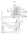
- FIG. 1 showing a vertical section through the central axis of a circular loom.
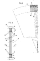
- Fig. 2 shows a detail of a section along the line II-II of Fig. 1 on an enlarged scale.
- FIG. 3 is a detail of a view in the direction of arrow III of FIG. 1.
- the circular loom has a drivable rotor 2 which is rotatably mounted in a machine frame 1 and which is arranged below a fixed circular-cylindrical reed 3.
- the reed 3 is delimited by a lower and an upper, ring-shaped race 4, 5, along which races at least one shooter 6 is guided by rollers 7. Between the races 4, 5 these connecting rods 8 of the reed 3 are provided, between which the warp threads 9, 10 are passed.
- the reed 3 concentrically surrounding thread guide members 12 are provided, which are formed by upper and lower guide rollers 13, 14 guided endless belts 15, to each of which a thread guide eye 16 is attached to each strand.
- the rotor 2 has a groove 17 (or spring) which runs in a wave-like manner over the circumference and on which driver elements 18 are guided.
- the driver elements 18 are connected to the belts 15 by means of actuating rods 19.
- thread tensioning devices 20 are provided for the warp threads 9, 10, which are formed by spring wires 21, which are each equipped with thread holders 22 at their free ends.
- the races 4, 5 have the guide surfaces 23 for the rollers 7 crossing thread guide grooves 24 for receiving the warp threads 9, 10 forming the compartment 11.
- the depth 25 of the thread guide grooves 24 is selected so that the warp threads 9, 10 do not lie against the bottom 26 of the thread guide grooves 24 when the compartment 11 is fully open (see FIG. 1), but come to lie at a short distance 27 therefrom.
- the webs 28 present between the thread guide grooves 24 have a width 29 which is twice as large as the width 30 of the thread guide groove 24.
- the guide surfaces 23 are thus only slightly interrupted by the thread guide grooves 24.
- the thread guide grooves 24 are aligned with the circumference of the Races 4, 5 arranged, formed by the reed 3 thread guides, the rods 8 of the reed 3 are each arranged in the extension of a web 28 outside the same.
- the thread guide grooves 24 are not arranged exactly radially to the central axis 31 of the machine, but they deviate from the radial direction in the running direction of the shooters 6 by an acute angle alpha, which ensures the smooth sliding or insertion of the Warp threads 9, 10, which are spread out by thread guides arranged on the shooter 6 and designed as thread guide brackets 32, are secured in the thread guide grooves 24.
- the insertion of the warp threads 9, 10 is further facilitated in that the thread guide grooves 24 have extensions 34 which are wedge-shaped at their ends directed towards the center 33 of the shed. These projections protrude beyond the guide surfaces 23 and at the same time form a support for the rollers 7 of the shooter 6.
- the acute angle alpha, with which the thread guide grooves 24 are arranged inclined with respect to the radial direction is preferably more than 1 °.
- a major advantage of the circular loom according to the invention can be seen in the fact that the warp threads 9, 10 - apart from the drive roller 35 driving the shooter 6 and rotatably mounted on the rotor 2 - only with the thread guide eyes 16 and with the thread guide bars 32 in the area of the compartment with machine parts come into contact so that you have a free hand in the construction of the guide surfaces 23 of the races 4, 5.
- the guide surfaces 23 are arranged inclined inwards and the upper guide surface 23 is provided with a support for the upper wheels 7 of the shooter 6, via which Guide surface 23 protruding inner edge 36 which prevents the shooter 6 from tipping inward when it is stationary.
- the races 4, 5 are advantageously made of plastic; they are assembled from initially straight-line sections, the individual sections having a foot 37, each of which is fitted into an annular groove 38 of the machine frame 1 and is fastened in this groove 38, for example by means of screws 39.
Landscapes
- Engineering & Computer Science (AREA)
- Textile Engineering (AREA)
- Looms (AREA)
- Auxiliary Weaving Apparatuses, Weavers' Tools, And Shuttles (AREA)
Applications Claiming Priority (2)
| Application Number | Priority Date | Filing Date | Title |
|---|---|---|---|
| AT1906/86 | 1986-07-14 | ||
| AT0190686A AT385784B (de) | 1986-07-14 | 1986-07-14 | Rundwebmaschine |
Publications (2)
| Publication Number | Publication Date |
|---|---|
| EP0253799A2 true EP0253799A2 (fr) | 1988-01-20 |
| EP0253799A3 EP0253799A3 (fr) | 1990-03-07 |
Family
ID=3523583
Family Applications (1)
| Application Number | Title | Priority Date | Filing Date |
|---|---|---|---|
| EP87890166A Withdrawn EP0253799A3 (fr) | 1986-07-14 | 1987-07-09 | Métier à tisser circulaire |
Country Status (6)
| Country | Link |
|---|---|
| US (1) | US4776371A (fr) |
| EP (1) | EP0253799A3 (fr) |
| JP (1) | JPS6328940A (fr) |
| CN (1) | CN1004560B (fr) |
| AT (1) | AT385784B (fr) |
| ZA (1) | ZA874928B (fr) |
Cited By (3)
| Publication number | Priority date | Publication date | Assignee | Title |
|---|---|---|---|---|
| EP3438335A1 (fr) * | 2017-08-01 | 2019-02-06 | Reinhold Hehenberger | Ros et métier à tisser circulaire |
| WO2019025043A1 (fr) | 2017-08-01 | 2019-02-07 | Reinhold Hehenberger | Métier circulaire |
| AT524953A4 (de) * | 2021-12-22 | 2022-11-15 | Protoh Og | Rundwebmaschine |
Families Citing this family (5)
| Publication number | Priority date | Publication date | Assignee | Title |
|---|---|---|---|---|
| JPH02293440A (ja) * | 1989-05-02 | 1990-12-04 | Torii Tekkosho:Kk | 円形織機のシャトル支持機構 |
| CN102747515B (zh) * | 2012-07-13 | 2013-09-25 | 太平洋机电(集团)有限公司 | 一种圆织机的引纬装置 |
| EP2829645B1 (fr) * | 2013-07-24 | 2018-09-05 | Starlinger & Co Gesellschaft m.b.H. | Métier à tisser circulaire |
| DE112017002308A5 (de) * | 2016-05-04 | 2019-03-14 | Innotec Lightweight Engineering & Polymer Technology Gmbh | Rundwebmaschine und Verfahren zur Herstellung eines hohlprofilartigen Gewebes |
| US11352721B2 (en) * | 2019-07-24 | 2022-06-07 | Innotec Lightweight Engineering & Polymer Technology Gmbh | Circular loom with orbit path |
Family Cites Families (8)
| Publication number | Priority date | Publication date | Assignee | Title |
|---|---|---|---|---|
| FR615015A (fr) * | 1926-04-24 | 1926-12-28 | Perfectionnements aux métiers à tisser circulaires | |
| FR800537A (fr) * | 1936-01-11 | 1936-07-07 | Cfcmug | Perfectionnements aux moteurs synchrones |
| US2248282A (en) * | 1939-07-18 | 1941-07-08 | Saint Freres Sa Soc | Device for guiding the shuttles in circular weaving looms |
| DE805026C (de) * | 1945-06-13 | 1951-05-04 | Comptoir Linier Sa | Elektrischer Rundwebstuhl |
| FR1388875A (fr) * | 1963-12-30 | 1965-02-12 | Dispositif d'entraînement et de freinage de navettes pour métiers à tisser circulaires | |
| NO122786B (fr) * | 1965-09-17 | 1971-08-09 | Peltzer & Fils Sa | |
| CS266317B2 (en) * | 1982-07-02 | 1989-12-13 | Franz Xaver Huemer | Circular weaving machine |
| CH663227A5 (de) * | 1984-06-08 | 1987-11-30 | Huemer Franz Xaver | Rundwebmaschine. |
-
1986
- 1986-07-14 AT AT0190686A patent/AT385784B/de not_active IP Right Cessation
-
1987
- 1987-07-07 ZA ZA874928A patent/ZA874928B/xx unknown
- 1987-07-08 CN CN87104791.8A patent/CN1004560B/zh not_active Expired
- 1987-07-09 US US07/071,291 patent/US4776371A/en not_active Expired - Fee Related
- 1987-07-09 EP EP87890166A patent/EP0253799A3/fr not_active Withdrawn
- 1987-07-13 JP JP62174578A patent/JPS6328940A/ja active Pending
Cited By (5)
| Publication number | Priority date | Publication date | Assignee | Title |
|---|---|---|---|---|
| EP3438335A1 (fr) * | 2017-08-01 | 2019-02-06 | Reinhold Hehenberger | Ros et métier à tisser circulaire |
| WO2019025043A1 (fr) | 2017-08-01 | 2019-02-07 | Reinhold Hehenberger | Métier circulaire |
| AT524953A4 (de) * | 2021-12-22 | 2022-11-15 | Protoh Og | Rundwebmaschine |
| AT524953B1 (de) * | 2021-12-22 | 2022-11-15 | Protoh Og | Rundwebmaschine |
| WO2023115091A1 (fr) | 2021-12-22 | 2023-06-29 | Starlinger & Co Gesellschaft M.B.H. | Métier à tisser circulaire |
Also Published As
| Publication number | Publication date |
|---|---|
| US4776371A (en) | 1988-10-11 |
| ZA874928B (en) | 1988-03-30 |
| CN87104791A (zh) | 1988-01-27 |
| CN1004560B (zh) | 1989-06-21 |
| ATA190686A (de) | 1987-10-15 |
| EP0253799A3 (fr) | 1990-03-07 |
| AT385784B (de) | 1988-05-10 |
| JPS6328940A (ja) | 1988-02-06 |
Similar Documents
| Publication | Publication Date | Title |
|---|---|---|
| DE3607524C2 (fr) | ||
| DE2941565C2 (de) | Kugelgewindetrieb | |
| DE2519448B1 (de) | Gewebeeinlage für quersteife fördergurte | |
| EP0080453A2 (fr) | Métier à tisser circulaire | |
| EP0253799A2 (fr) | Métier à tisser circulaire | |
| DE2519364A1 (de) | Vorrichtung zur geradlinigen fuehrung | |
| EP0257500A2 (fr) | Dispositif pour diriger l'air | |
| DE2803377C2 (de) | Vorrichtung zum Changieren eines Fadens in Spulmaschinen | |
| CH663648A5 (de) | Rollenumlauflager. | |
| EP0253798A2 (fr) | Métier à tisser circulaire | |
| EP0004593A1 (fr) | Douille à billes pour déplacements linéaires | |
| DE2648696A1 (de) | Spielzeug | |
| EP0141283A1 (fr) | Cylindre rotatif garni d'aiguilles pour machines textiles | |
| EP0213462B1 (fr) | Guide-fil à va-et-vient | |
| DE69307813T2 (de) | Querelement für endloses Antriebsorgan | |
| EP0174533B1 (fr) | Dispositif d'exécution d'une lisière à pas de gaze | |
| EP0900952B1 (fr) | Transmission à courroie | |
| DE2253729C3 (de) | Breithalterzylinder | |
| DE2242755B2 (de) | Ballonbegrenzerring | |
| DE3222600A1 (de) | Nadelstabstreckwerk | |
| DE4006733C2 (de) | Seilzuganlage, insbesondere Seilzuglinearwischeranlage für Kraftfahrzeuge | |
| EP0929706B1 (fr) | Procede et dispositif pour vriller au moins deux fils en deplacement l'un autour de l'autre | |
| DD250963B1 (de) | Pneumatische reinigungsvorrichtung fuer textilmaschinen, insb. fuer wellenfachwebmaschinen | |
| EP1070163A2 (fr) | Dispositif d'entrainement pour les lames partielles de metiers a tisser circulaires | |
| DE2902826C2 (de) | Nockenschaltwalze |
Legal Events
| Date | Code | Title | Description |
|---|---|---|---|
| PUAI | Public reference made under article 153(3) epc to a published international application that has entered the european phase |
Free format text: ORIGINAL CODE: 0009012 |
|
| AK | Designated contracting states |
Kind code of ref document: A2 Designated state(s): DE GB IT |
|
| PUAL | Search report despatched |
Free format text: ORIGINAL CODE: 0009013 |
|
| AK | Designated contracting states |
Kind code of ref document: A3 Designated state(s): DE GB IT |
|
| STAA | Information on the status of an ep patent application or granted ep patent |
Free format text: STATUS: THE APPLICATION IS DEEMED TO BE WITHDRAWN |
|
| 18D | Application deemed to be withdrawn |
Effective date: 19900908 |
|
| RIN1 | Information on inventor provided before grant (corrected) |
Inventor name: NUSSDORFER, FRANZ, DIPL.-ING. Inventor name: SCHOENBERGER, JOHANN Inventor name: ROMAUER, EWALD Inventor name: KIENESBERGER, KARL Inventor name: ZACEK, FRANZ, DIPL.-ING. Inventor name: PICHLER, HERMANN Inventor name: WOLF, RUDOLF Inventor name: FOEDINGER, FRANZ |