EP0253864B1 - Aerodynamische und das beschlagen verhindernde vorrichtung für die schale und das visier eines schutzhelmes - Google Patents
Aerodynamische und das beschlagen verhindernde vorrichtung für die schale und das visier eines schutzhelmes Download PDFInfo
- Publication number
- EP0253864B1 EP0253864B1 EP19870900829 EP87900829A EP0253864B1 EP 0253864 B1 EP0253864 B1 EP 0253864B1 EP 19870900829 EP19870900829 EP 19870900829 EP 87900829 A EP87900829 A EP 87900829A EP 0253864 B1 EP0253864 B1 EP 0253864B1
- Authority
- EP
- European Patent Office
- Prior art keywords
- screen
- shell
- sight
- raisable
- axis
- Prior art date
- Legal status (The legal status is an assumption and is not a legal conclusion. Google has not performed a legal analysis and makes no representation as to the accuracy of the status listed.)
- Expired - Lifetime
Links
- 238000013519 translation Methods 0.000 claims description 14
- 230000009471 action Effects 0.000 claims description 10
- 239000000463 material Substances 0.000 claims description 8
- 230000015572 biosynthetic process Effects 0.000 claims description 5
- 210000003128 head Anatomy 0.000 claims description 3
- 239000003595 mist Substances 0.000 claims 1
- 230000001360 synchronised effect Effects 0.000 claims 1
- XLYOFNOQVPJJNP-UHFFFAOYSA-N water Substances O XLYOFNOQVPJJNP-UHFFFAOYSA-N 0.000 abstract description 5
- 235000005921 Cynara humilis Nutrition 0.000 description 10
- 240000002228 Cynara humilis Species 0.000 description 10
- 238000005304 joining Methods 0.000 description 5
- 238000009423 ventilation Methods 0.000 description 5
- 230000000670 limiting effect Effects 0.000 description 4
- 230000000694 effects Effects 0.000 description 3
- 210000002445 nipple Anatomy 0.000 description 3
- 230000036961 partial effect Effects 0.000 description 3
- 208000003164 Diplopia Diseases 0.000 description 2
- 238000013459 approach Methods 0.000 description 2
- 238000013461 design Methods 0.000 description 2
- 208000029444 double vision Diseases 0.000 description 2
- 238000009434 installation Methods 0.000 description 2
- 238000000034 method Methods 0.000 description 2
- 230000001681 protective effect Effects 0.000 description 2
- 230000000284 resting effect Effects 0.000 description 2
- 238000000926 separation method Methods 0.000 description 2
- 241000238631 Hexapoda Species 0.000 description 1
- 230000004075 alteration Effects 0.000 description 1
- 230000008901 benefit Effects 0.000 description 1
- 238000006243 chemical reaction Methods 0.000 description 1
- 230000008878 coupling Effects 0.000 description 1
- 238000010168 coupling process Methods 0.000 description 1
- 238000005859 coupling reaction Methods 0.000 description 1
- 230000007547 defect Effects 0.000 description 1
- 238000010586 diagram Methods 0.000 description 1
- 230000009977 dual effect Effects 0.000 description 1
- 239000000428 dust Substances 0.000 description 1
- 230000006872 improvement Effects 0.000 description 1
- 238000012423 maintenance Methods 0.000 description 1
- 238000004519 manufacturing process Methods 0.000 description 1
- 238000000465 moulding Methods 0.000 description 1
- 238000003825 pressing Methods 0.000 description 1
- 230000009467 reduction Effects 0.000 description 1
- 230000002441 reversible effect Effects 0.000 description 1
- 125000006850 spacer group Chemical group 0.000 description 1
- 238000013517 stratification Methods 0.000 description 1
- 210000004243 sweat Anatomy 0.000 description 1
- 210000002105 tongue Anatomy 0.000 description 1
- 230000000007 visual effect Effects 0.000 description 1
Images


Classifications
-
- A—HUMAN NECESSITIES
- A42—HEADWEAR
- A42B—HATS; HEAD COVERINGS
- A42B3/00—Helmets; Helmet covers ; Other protective head coverings
- A42B3/04—Parts, details or accessories of helmets
- A42B3/0493—Aerodynamic helmets; Air guiding means therefor
-
- A—HUMAN NECESSITIES
- A42—HEADWEAR
- A42B—HATS; HEAD COVERINGS
- A42B3/00—Helmets; Helmet covers ; Other protective head coverings
- A42B3/04—Parts, details or accessories of helmets
- A42B3/18—Face protection devices
- A42B3/22—Visors
- A42B3/221—Attaching visors to helmet shells, e.g. on motorcycle helmets
- A42B3/222—Attaching visors to helmet shells, e.g. on motorcycle helmets in an articulated manner, e.g. hinge devices
-
- A—HUMAN NECESSITIES
- A42—HEADWEAR
- A42B—HATS; HEAD COVERINGS
- A42B3/00—Helmets; Helmet covers ; Other protective head coverings
- A42B3/04—Parts, details or accessories of helmets
- A42B3/18—Face protection devices
- A42B3/22—Visors
- A42B3/226—Visors with sunscreens, e.g. tinted or dual visor
-
- A—HUMAN NECESSITIES
- A42—HEADWEAR
- A42B—HATS; HEAD COVERINGS
- A42B3/00—Helmets; Helmet covers ; Other protective head coverings
- A42B3/04—Parts, details or accessories of helmets
- A42B3/18—Face protection devices
- A42B3/22—Visors
- A42B3/24—Visors with means for avoiding fogging or misting
Definitions
- the present invention relates to a protective helmet for motorcyclists designed to be equipped with a double vision screen system of the kind described in patent FR-A-2,532,528.
- the vision screen comes down to a transparent screen articulated on two lateral and opposite points of the external surface of the hull.
- dismantling this screen requires the use of one or more tools.
- a screen in the closed position, completely closes the corresponding cutout made in the shell and delimiting the useful field of vision.
- the almost non-existent ventilation inside the helmet favors the formation of fogging on the screen in cold weather, and in hot weather ... that of sweat on the user.
- we raise the screen we allow the air mixed with dust and insects to rush in an anarchic way inside the helmet where turbulence is created which is incompatible with comfort - notably the user's visual .
- the aerodynamic resistance linked to the volume of the helmet which, applying a rearward action to it, requires the user to have to respond to it with a reaction towards the before.
- the aerodynamic force pulling the helmet back is due less to the direct pressure of the air against the front face of the helmet than to the suction of the rear part of the helmet due to the turbulence of the air streams and to the resulting depression.
- the helmet according to the invention proposes to remedy these defects by the use of a system of double vision screen adapted - according to a preferred and complete variant of the invention - to a specific shell.
- one of the two screens is, in the closed position, integrated into the line of the hull and offers the particularity of being able to be raised, outside the hull, without however harming the aerodynamic qualities of this one.
- the second screen whose height is, at least in its central zone, lower than that of the external screen, meanwhile, is raised inside the hull. The presence of this second screen combined with a judicious ventilation system makes it possible to fight effectively against the formation of fogging.
- This ventilation system consists of an air intake made in the frontal area of the hull or the upper part of the exterior screen. To be effective, this air inlet must be associated with two outlets - of larger total section -, thus forming a low pressure system sucking the air inside the helmet. These outputs are openings made in the two lateral zones of the external screen, close to each of its ends. In order to increase the efficiency of the low pressure system by accelerating the circulation of air tangentially to these outlets, each end of the screen is fitted with a cover covering the air outlets, open towards the front and towards the rear, the section of the rear opening being the largest.
- this ventilation system the whole of this ventilation system - the front air inlet opening below the upper edge of the interior screen - has the effect of forming a moving air film between the two screens, hence its effectiveness as an anti-fog, the air exhaled by the user being below the lower edge of the interior screen.
- this system prevents the user from receiving cold air from the front air inlet directly into the eyes.
- the height of the interior screen being sufficient to ensure eye protection, it allows good driving comfort for a user preferring to roll the exterior screen fully raised.
- this short screen can be tinted and used or not at will and instantly with the external screen whenever the light conditions require it, the movements of the two screens being independent of each other, the interior screen being actuated by means of a member accessible by the user whatever the position of the exterior screen.
- the interior screen is articulated on two lateral and opposite points of the shell located on the same axis perpendicular to the vertical longitudinal median plane of the helmet. The material axes carrying these joints are internal to the hull. This screen is raised by sliding between the shell itself and the external surface of the shell fitted for this purpose: recesses and possibly direct stratification or internal double shell. The method of attachment and articulation chosen allows disassembly and assembly easy and without tools.
- This method of attachment consists of a cut other than cylindrical made at each end of the screen and emerging therein. These cutouts when setting up the screen engage on male parts of corresponding section linked to the internal face of the shell but free in rotation relative to the latter. The connection between the ends of the screen and the parts on which they engage is then comparable to that of a flat key with a screw head. This connection allows the rotation of the screen around a fixed axis relative to the shell. A combination of hollows and bumps formed between the surface of the shell and one of the moving parts and resting against it - the screen or the parts which carry it - ensures the rotational positioning of the screen: raised position, lowered and "disassembly".
- a suitable elastic system pressing against the internal face of the screen at each of its articulations maintains the pressure between the other face of the screen and the part which carries it as well as possibly between this last part and the inner side of the hull.
- Another combination of hollows and bumps between the screen and one of the cooperating parts ensures the translational connection of the screen relative to the shell.
- the screen itself which, when it is positioned below its normal position of use, is freed from the nipple or boss ensuring its connection in translation relative to the shell, either by sliding on an inclined plane tending to move it away from the shell or away from it the part or part of part pushing each of its ends towards the shell, either that it has a groove or a rim in an arc of a circle, in or against which the nipple circulates , opening to the outside of the screen at the level reached by the nipple when the screen is in its disassembly position. Then simply remove the screen by pulling it out of the helmet.
- the screen is operated by action on a lever extending on at least one side, towards the base of the shell, the part to which the screen is linked in rotation, or the screen itself. even.
- the outer screen is, in the closed position, integrated into the line of the hull, its external surface is completely in the extension of that of the hull, forming no protrusion with it.
- the opening movement then decomposes in at least two stages: the first, of apparent translation forward, away from the hull. Simultaneously, the ends of the screen are also detached laterally from the surface of the hull for easy subsequent lifting.
- This advanced position of the screen is a position that can advantageously be taken to the screen to allow efficient ventilation and without turbulence, due more to the depression than to the direct action of the wind, inside helmet.
- the screen can be raised according to a rotational movement bringing it opposite the surface of the shell against which it will be pressed, by a new movement in translation, against the shell.
- the screen can also be raised, above the frontal zone, up to the upper part of the shell and kept a few millimeters from the surface thereof, slightly inclined relative to it so as to form an aerodynamic flap whose cross section of the air inlet between the internal face of the screen and the shell is less than that of the outlet towards the back.
- the screen thus raised behaves like an aerodynamic flap, the speed differential between the air streams drawn in and laminated between the shell and the screen on the one hand and the air flow passing over the screen on the other hand, having the effect of repositioning the air streams against the rear of the hull, thereby limiting the surface thereof subjected to vacuum.
- Such an aerodynamic flap can also, independently of the vision screen, be adapted to a helmet and treated in the form of a fixed adjustable or removable hoop which would have the advantage of being able to fulfill its role, even the screen being in position. lowered.
- such a hoop is designed as an outer double shell open towards the front and towards the rear and inside which the screen can possibly be housed in the raised position.
- the external screen in order not to be aerodynamic discomfort when it is in the raised position, is characterized in that its internal face offers a profile identical in all respects to that of the external surface of the hull in the area against which it can be pressed in the raised position.
- the radius "R" of the external frontal curve of the shell is equal - or less, in the value of a functional clearance - than that of the curve of the internal face of the screen in this same plane.
- the "X" axis is fixed relative to the screen, movable relative to the shell, perpendicular to the vertical longitudinal median plane of the helmet and passing through the mobile point of this plane, center of the circle of radius "R” generating the internal surface of the screen, is in a position "X"'fixed relative to the shell, when the screen is in the closed position.
- This "X” axis is not necessarily confused with the "Y” axis parallel to "X”, but fixed relative to the shell and passing through the point of the vertical longitudinal median plane of the helmet which is also the center of the circle with the same radius "R” generating the external surface of the hull in its frontal area.
- the vision screen is itself articulated by each of its ends along an axis "U” - parallel to "X” and at "Y” - on an intermediate part - generally a disc or rod - itself articulated on the hull according to an axis of rotation "V" parallel to "U” but not confused with it.
- This part optionally bears on its face against which the screen comes to bear, a second material axis which can, during movements of the screen, circulate in a groove made in the screen.
- This axis may or may not coincide with the "V" axis depending on the variant embodiments.
- this articulated assembly allows by a rotational movement of the intermediate piece around its axis V, to bring the screen still in the lowered position in its advanced position of use relative to the shell, in a movement comparable to that of a connecting rod.
- the quality of this translational movement is improved if the "U" axis is engaged in a groove made in the screen in place of an adjusted cylindrical bore. Then, by a rotation of the screen around the axis "U”, with respect to the intermediate piece, one passes from the lowered position to the raised position.
- the screen By a new movement of rotation of the intermediate part around the axis "V", the screen is pressed against the shell thus bringing the axis "X” in coincidence with "Y".
- the position of "X” is further modified by acting on the rotation of the intermediate piece around the "V” axis and of the screen around the "U” axis.
- the separation of the ends of the screen from the lateral zones of the hull is ensured by a combination of inclined planes between two surfaces which are movable relative to one another and resting on one another : intermediate-shell part, intermediate-screen part or screen-shell.
- one of the material axes joining the screen to the shell according to "V" or "U” is equipped with a helical system cooperating with the bore in which it is introduced.
- the maintenance and the guiding of the latter are completed by the action of one or more studs integral with the shell or with the intermediate piece, fixed relative to this support, around which are guided lights or grooves made in the screen and acting as cams limiting the amplitude of the different movements and according to which the rotational movements of the intermediate piece around the "V" axis and of the screen around the "U” axis are decomposed or simultaneous.
- a cover, open towards the front and towards the rear - the screen being in the closed position - is fixed on each end of the screen, above the side air outlets, which can be combined with a "cam groove” useful for guiding the screen.
- Such a cover, fixed relative to the screen moves with it relative to the shell. During its installation, it can, by clipping, above the screen, around the head of the material axis "U" - if it passes through a cylindrical bore of the same diameter practiced in the visor - used for easy and removable attachment without tools, of the visor on the intermediate piece and therefore on the helmet.
- each end of the screen is linked, permanently or removable, to a flat part extending it, through which the bores, grooves, lights or functional bosses normally appearing are practiced. on the screen itself.
- This in particular in order to have a tool - mold for manufacturing the screen - simplified.
- each end of the screen is engaged in a flat piece extending it and has a possibility of movement in translation relative to this piece through which the grooves are also made, functional lights or bosses normally appearing on the screen itself.
- a combination of inclined planes between two surfaces bearing against one another and movable with respect to each other then makes it possible, during the translational movement of the screen relative to the part extending it, to take off the screen from the lateral zones of the helmet in order to make its lifting movement - by rotation around the "U" axis of the pieces extending each end of the screen - easy.
- the shell in its frontal area, just above the edge upper part of the external vision screen - in the lowered position - sees its external surface arranged so as to form a series of grooves-like grooves - or reliefs substantially parallel to each other and with the upper edge of the vision screen, each extending over a length at least equal to that of the vision screen.
- these "rain-proof waves” are - in the vertical longitudinal median plane of the helmet - in relief with respect to the general curve of radius "R” in the frontal area of the hull, they can constitute a device making it possible to give the shell in the area near the upper edge of the vision screen in the closed position a local radius of curvature of the value of "R” increased by the material thickness of the exterior screen.
- the exterior screen - the interior face of which retains a radius of curvature of value "R" equal, apart from the functional clearance, to that of the hull in the area, above the rain system, against which it can be placed in the raised position - may, while offering, in the closed position the appearance of a screen completely integrated into the line of the hull, have - as in the alternative embodiment according to which the external screen is not, in the closed position, not integrated into the hull line - its "X" axis in a "X"'position where "X"' is confused with "Y".
- any vision screen used alone on a helmet but being in the form of a single screen with double walls - separated by a space sufficient to allow the circulation of a film of air - joining at the upper edge of the screen, not joining - at least in the central zone - at their lower edges, the height of the internal wall being - at least in its central zone - lower than that of the outer wall, the front air inlet and the side air outlets being pierced through the outer wall.
- Such a single double-walled screen is molded or formed from two thermoformed or curved screens assembled together by being separated by a spacer at their upper edges and at their ends.
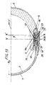
- X is the theoretical axis, perpendicular to the vertical and longitudinal median plane (p) of the helmet, passing through the point of this plane which is also the center of the circle of radius "R + j" corresponding to the radius of curvature, in the plane (p), of the internal face of the external screen.
- "X” is an axis movable relative to the shell, fixed relative to the screen with which it moves.
- V is the axis of the hull, parallel to "X” 'and “Y”, according to which the intermediate parts between the outer screen and the hull are articulated to the hull, on either side of it this.
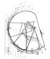
- FIG. 1 makes it possible to observe the turbulence which forms both at the rear and - when the screen is raised - at the front of a helmet fitted with a vision screen of known type.
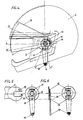
- Figure 2 shows the movement of a screen 1 according to the invention. From the closed position (a), it passes, thanks to the action imparted to the operating member 3 in its advanced position (c). From there, by a rotational movement, he arrives at the position (d). Subjected to a force T ", it can then be pressed against the shell 2 of which it follows the profile -position (e) -. A force r applied to each end of the screen causes it to go from (e) to (f ), position in which it takes the inclination required to fulfill the function of aerodynamic flap which, after a new rotation, it occupies in position (g).
- Figure 3 illustrates how the dual vision screen system works in its anti-fog function.
- the air entering the interior of the hull through the orifices 5 is blocked between the two screens and sucked towards the lateral zones by the effect of the depression due to the presence of the orifices 28 formed through the outdoor display presence 1.
- a combination of hollows and hemispherical bosses 12 between the surface of the part 9 bearing against and the shell and the shell itself ensures the posititionment in rotation of the screen 7 relative to the shell .
- the interior screen is housed between the shell 2 and the double shell 13.
- the translational positioning of the screen relative to the shell is provided by the boss 14 formed on the internal surface of the shell and around which circulates the groove 15 formed in the screen. This boss 14 also has the function of limiting the amplitude of the rotational movement of the screen.
- the "U" axis belonging to the part 21 passes through a light in an arc 22 of the screen 1.
- the "U” axis is coincident with the "X" axis, shown here in its "X” position.
- the part 21 is itself linked in rotation by a central axis "V" introduced inside the tubular axis 17 of the shell.
- the illustrated helmet representing an alternative embodiment in which the screen 1 is - in the closed position (a) - fully integrated into the line of the shell, including in its lateral zones, a combination of inclined planes 26-26 'practiced at the external surface of the shell and on the surface of the part 21 bearing against the shell allows, when the axis "U", by a rotation of the intermediate part 21 around the axis "V” arrives in coincidence with l axis "Z” - the screen 1 then being in its position (c) - to take off the two ends of the screen from the hull of a sufficient value to allow easy lifting of the screen to the position (d).
- the screen 1 thus detached from the shell 2- position (f) -, can then be raised according to a rotational movement around the axis "U" in its position (g).
- the guiding of the screen is ensured, in addition to the circulation of the axis 23 in the lumen 30, by that of the axis 27 in light 28 which it comes out at 29.
- the axis 31 belonging to the shell engages in the groove 32 of the screen, thus taking the "relay" from the axis 27 previously associated with the groove 28. From the position (e) of the screen, you can also return it to its lowered position (c).
- the edges of each end of the screen 1 equipped with slides 33 allow, by a translation along T, the fixing of the cover 19 equipped with the slides 34 cooperating with 33.
- the combination of hollows and bosses 35-36 between the screen and the cover ensures the positioning of these elements between them.
- the operating member 3 is a sliding button on a rail 39 formed at the base of the shell 2.
- the cable 37 which is linked to it passes around an axis - or a small pulley 38 - secured to the internal surface of the shell 2, before joining - by first circulating inside the helmet then in a groove 41 formed outside the shell and itself joining the counterbore 42 serving to house the part 21 - the part 21 to the periphery of which it circulates in a groove 43, to be fixed there by introduction of the cylinder 40 - crimped on it - in the bore 40 'of the part 21.
- each end of the screen is fixed to part 21 or 21' by means of two screws 45-46 on the axes "U" and 23. It is accessed after removing the side covers 19.
- the groove 47 formed in the bore of the tubular axis 17 of the shell 2, wider than the elastic ring 25 allows the part 21 to have relative to the shell 2 sufficient freedom in translation to ensure the separation of the ends of the screen necessary for easy lifting thereof.
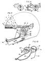
- FIG. 14 shows another embodiment of an external screen 49 according to the invention.
- the screen 49 is articulated on the part 51 along a cylindrical axis "U" coincident with "X" passing through a cylindrical cutout of the same diameter, apart from the functional clearances, practiced in the screen.
- the lifting movement is simpler here, the raised position being the only position (e). From these two elements follow the design of "cam grooves" 52-54.
- the cover 55 allows, thanks to a shape 56 coming to engage in a groove formed around the axis "U” above the screen, to ensure by itself the connection between the screen 49 and the part 51 .
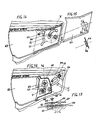
- FIG. 16 presents another variant in which the screen 57 proper has its ends extended by parts 64. It is these parts 64 which receive the axis "U" and the groove 59 cooperating with a stud 58 of the shell for guiding the screen.
- the screen 57 is detachably linked to the part 64 by these ends each housed in a counterbore 60 of the part 64, and pierced with cutouts 62 in which the bosses 66 of the cover 67 engage, itself even fixed on the piece 64, above the screen, by three screws 65.
- the screen is also used here to ensure the connection between the piece 64 and the piece 85 by clipping one of its cutouts in a groove made around the axis "U" above the part 64.
- the screen changes from position (a) to position (e) due to a rotation of the part 85 around the axis "V” at an angle close to 360 °, and not as in the cases studied previously according to an angular sector passing the axis "U” from position "X"'to position “Z” and vice- vice versa.
- FIG. 18 shows another alternative embodiment of an external screen 68 in which each end of the screen 68 proper is engaged in a counterbore 77 in one piece 75.
- the edges of the counterbore 77 serve as slides for the screen 68, which can move in translation relative to the part 75.
- a boss 76 of the external surface of the shell forms an inclined plane passing through a lumen 71 of the part 75 and another lumen 79 of the ends of the screen.
- a stud 70 of the part 75 passing through the light 79 of the screen limits the amplitude of the movements in translation of the latter relative to the part 75.
- the elastic system holding each end of the external screen, and the annexed parts to which they are linked, bearing against the shell is constituted by the elasticity of the screen itself, of which the radius of curvature, when disassembled, is - in a horizontal plane like that, according to EE, shown in Figure 3 - less than that of the hull in this same plane.
- Other means such as springs could equally be used for this purpose.
- FIG 19 is a simplified alternative embodiment of the double anti-fog screen system according to the invention.
- the screen 82 can alone fulfill this function since it has two walls 80-81 which meet at their upper edge.
- the inlets 84 and the air outlets 83 are formed through the single outer wall 80.
- the inner wall 81 also joins the wall 80 in the lateral zone close to the ends of the screen 82, behind the air outlets 83.
- the object of the invention can be adopted advantageously by any manufacturer of protective helmets of all kinds, both of the so-called “integral” type and of the so-called “jet” or “semi-open” type.
Landscapes
- Physics & Mathematics (AREA)
- Fluid Mechanics (AREA)
- Helmets And Other Head Coverings (AREA)
Claims (16)
Applications Claiming Priority (2)
| Application Number | Priority Date | Filing Date | Title |
|---|---|---|---|
| FR8600909 | 1986-01-21 | ||
| FR8600909A FR2593035B1 (fr) | 1986-01-21 | 1986-01-21 | Systeme aerodynamique et antibuee de coque et d'ecran de vision d'un casque de protection. |
Publications (2)
| Publication Number | Publication Date |
|---|---|
| EP0253864A1 EP0253864A1 (de) | 1988-01-27 |
| EP0253864B1 true EP0253864B1 (de) | 1990-06-27 |
Family
ID=9331399
Family Applications (1)
| Application Number | Title | Priority Date | Filing Date |
|---|---|---|---|
| EP19870900829 Expired - Lifetime EP0253864B1 (de) | 1986-01-21 | 1987-01-19 | Aerodynamische und das beschlagen verhindernde vorrichtung für die schale und das visier eines schutzhelmes |
Country Status (4)
| Country | Link |
|---|---|
| EP (1) | EP0253864B1 (de) |
| AU (1) | AU6899087A (de) |
| FR (1) | FR2593035B1 (de) |
| WO (1) | WO1987004323A1 (de) |
Cited By (1)
| Publication number | Priority date | Publication date | Assignee | Title |
|---|---|---|---|---|
| DE102005001804A1 (de) * | 2004-10-04 | 2006-07-27 | Schuberth Engineering Ag | Sturzhelm |
Families Citing this family (22)
| Publication number | Priority date | Publication date | Assignee | Title |
|---|---|---|---|---|
| JPS63309612A (ja) * | 1987-06-09 | 1988-12-16 | 新井 理夫 | ヘルメットにおけるシ−ルドの取付構造 |
| JPH0660444B2 (ja) * | 1987-06-09 | 1994-08-10 | 理夫 新井 | ヘルメットにおけるシールドの取付構造 |
| US5014366A (en) * | 1990-02-26 | 1991-05-14 | Discipio Sr William R | Enhanced visibility helmet |
| JPH0448219U (de) * | 1990-08-22 | 1992-04-23 | ||
| GB9200833D0 (en) * | 1992-01-15 | 1992-03-11 | Ayres David | Visor assembly |
| IT1255709B (it) * | 1992-10-01 | 1995-11-10 | Nolan Helmets Spa | Casco protettivo per motociclisti e simili, provvisto di mezzi regolabili di schermatura della radiazione luminosa incidente |
| FR2724541B1 (fr) * | 1994-09-20 | 1996-12-06 | Sextant Avionique | Paire d'articulations a manoeuvres synchronisees pour la fixation d'une visiere escamotable sur un casque |
| GB2303872B (en) * | 1995-08-01 | 1999-01-20 | Gec Marconi Avionics Holdings | Helmet visor release apparatus |
| FR2759869A1 (fr) * | 1997-02-21 | 1998-08-28 | Jcp Ind | Dispositif de protection cephalique, notamment casque integral de moto |
| FR2773051B1 (fr) * | 1997-12-29 | 2000-03-17 | Gallet Sa | Perfectionnement pour casque de protection |
| DE19814916C2 (de) * | 1998-04-03 | 2002-08-29 | Schuberth Werk Gmbh | Schutzhelm, insbesondere Sturzhelm |
| JP4428754B2 (ja) * | 1998-07-16 | 2010-03-10 | 株式会社Shoei | ヘルメット |
| CA2422239A1 (en) | 2002-03-12 | 2003-09-12 | Bombardier Inc. | Breathing mask adjuster |
| KR100427684B1 (ko) * | 2002-05-31 | 2004-04-28 | 주식회사 에이치제이씨 | 헬멧용 시일드 결합장치 |
| DE60221011T2 (de) * | 2002-09-02 | 2008-03-13 | Osbe Srl, Moncalieri | Schutzhelm mit Sonnenblende, insbesondere für Motorradfahrer |
| ES2265216B1 (es) * | 2004-03-12 | 2008-02-01 | Manufacturas Tomas, S.A. | Sistema de anclaje de pantallas protectoras en cascos. |
| FR2876882B1 (fr) * | 2004-10-27 | 2007-03-02 | Shark Sa Sa | Casque de protection a mentonniere mobile, notamment pour le motocyclisme |
| ITMI20061774A1 (it) * | 2006-09-18 | 2008-03-19 | Locatelli S P A | Casco di sicurezza particolarmente per l'uso motoristico e sportivo in generale |
| WO2010066278A1 (fr) * | 2008-12-14 | 2010-06-17 | Lazer S.A. | Casque de protection a visiere solaire retractable |
| FR2986141B1 (fr) * | 2012-01-26 | 2015-03-27 | Msa Gallet | Casque de protection equipe d’un ecran facial mobile |
| IT201700021390A1 (it) * | 2017-02-24 | 2018-08-24 | Ci Erre E S R L | Casco protettivo con visiera/occhiale ribaltabile. |
| IT201900023955A1 (it) * | 2019-12-13 | 2021-06-13 | Ci Erre E S R L | Casco di protezione. |
Family Cites Families (14)
| Publication number | Priority date | Publication date | Assignee | Title |
|---|---|---|---|---|
| DE7035512U (de) * | 1970-09-25 | 1971-03-04 | Roemer Fa Hans | Schutzhelm mit schwenkbaren, gewoeloten visier. |
| US3727235A (en) * | 1972-01-13 | 1973-04-17 | Ilc Ind Inc | Retractable face protective assembly |
| US3897597A (en) * | 1972-05-31 | 1975-08-05 | Dale R Kasper | Face and head protector |
| IT1050962B (it) * | 1975-10-13 | 1981-03-20 | Sole Spa | Casco perfezionato per piloti |
| DE2640996A1 (de) * | 1976-09-11 | 1978-03-16 | Schuberth Werk Kg | Sturzhelm |
| CH610740A5 (en) * | 1977-01-17 | 1979-05-15 | Kiwi Sa | Integral helmet with movable visor for general sports use |
| IT1109155B (it) * | 1978-01-11 | 1985-12-16 | Nava Pier Luigi | Casco con visiera ribaltabile,particolarmente per motociclisti e simili |
| IT1108880B (it) * | 1978-10-03 | 1985-12-16 | Landi Cesare | Dispositivo atto a permettere la rotazione ed il posizionamento della visiera di un casco sportivo |
| IT1108182B (it) * | 1978-10-03 | 1985-12-02 | Camillo Pasquale | Dispositivo per il movimento rapido dello schermo fotoassorbente di maschere di protezione e caschi in genere particolarmente maschere per saldatori e caschi per motociclisti |
| DE3006596A1 (de) * | 1979-02-26 | 1980-09-04 | Kangol Helmets Ltd | Schutzhelm |
| IT8122834U1 (it) * | 1981-09-09 | 1983-03-09 | Nolan Spa | Guarnizione attrezzata per visiere di caschi integrali. |
| FR2532528B1 (fr) * | 1982-09-03 | 1985-06-07 | Galet Adrien | Casque de protection |
| DE3305735A1 (de) * | 1983-02-18 | 1984-08-30 | Bayerische Motoren Werke AG, 8000 München | Schutzhelm fuer motorradfahrer oder dergleichen |
| FR2541874A1 (fr) * | 1983-03-01 | 1984-09-07 | Gallet Fils Ets Jean | Mecanisme de liaison entre l'ecran et la calotte d'un casque de protection |
-
1986
- 1986-01-21 FR FR8600909A patent/FR2593035B1/fr not_active Expired
-
1987
- 1987-01-19 WO PCT/FR1987/000019 patent/WO1987004323A1/fr not_active Ceased
- 1987-01-19 EP EP19870900829 patent/EP0253864B1/de not_active Expired - Lifetime
- 1987-01-19 AU AU68990/87A patent/AU6899087A/en not_active Abandoned
Cited By (1)
| Publication number | Priority date | Publication date | Assignee | Title |
|---|---|---|---|---|
| DE102005001804A1 (de) * | 2004-10-04 | 2006-07-27 | Schuberth Engineering Ag | Sturzhelm |
Also Published As
| Publication number | Publication date |
|---|---|
| FR2593035A1 (fr) | 1987-07-24 |
| EP0253864A1 (de) | 1988-01-27 |
| AU6899087A (en) | 1987-08-14 |
| WO1987004323A1 (fr) | 1987-07-30 |
| FR2593035B1 (fr) | 1988-06-10 |
Similar Documents
| Publication | Publication Date | Title |
|---|---|---|
| EP0253864B1 (de) | Aerodynamische und das beschlagen verhindernde vorrichtung für die schale und das visier eines schutzhelmes | |
| FR3092650A1 (fr) | Event à élément aérodynamique pour réguler un flux d’air | |
| EP2976957B1 (de) | Schutzhelm mit beweglichem kieferschild mit automatischem displayerfassungsmechanismus | |
| EP0702906B1 (de) | Synchronisiertes Gelenkpaar zur schwenkbaren Befestigung eines Visiers an einem Helm | |
| FR2774561A1 (fr) | Perfectionnement pour moyens de maintien d'un casque de protection | |
| FR2828386A1 (fr) | Ecran de vision coupe-vent | |
| EP1219189B1 (de) | Reithelm mit Belüftungseinrichtung | |
| EP3195745B1 (de) | Visier und mit einem solchen visier ausgestatteter helm | |
| EP3169174B1 (de) | Schutzhelm mit eingebautem beweglichen visier | |
| FR3029852A1 (fr) | Systeme de toit pour un vehicule cabriolet | |
| FR2572456A1 (fr) | Fenetre a aeration automatique. | |
| EP1815761B1 (de) | Helm mit Atemmaske | |
| FR2498060A1 (fr) | Coiffure de protection, notamment pour motocyclistes et skieurs | |
| FR2883544A1 (fr) | Dispositif destine a compenser des perturbations provoquees par un vent lateral sur un vehicule automobile | |
| EP0506542B1 (de) | Lamellenluftleitblech, insbesondere für Kraftfahrzeuge | |
| EP0628261A1 (de) | Vorrichtung zur gelenkigen Befestigung einer Visierscheibe an einem Helm | |
| FR2721862A1 (fr) | Structure de separation entre espaces d'un dispositif de climatisation de vehicules | |
| FR2672778A1 (fr) | Casque pourvu d'un equipement optoelectronique. | |
| FR2884180A1 (fr) | Deflecteur d'air | |
| FR2828385A1 (fr) | Ecran de vision coupe-vent | |
| FR2655432A1 (fr) | Masque de vision. | |
| EP1598229A1 (de) | Fahrzeug mit einem Dachaufbau, der mit einem schwenkbaren Deckel versehen ist | |
| FR3150082A1 (fr) | Casque ventilé | |
| FR2719812A1 (fr) | Porte latérale pour véhicule automobile et agencement de cette porte sur le véhicule. | |
| FR2501478A1 (fr) | Casque de protection, notamment pour motocyclistes et cyclomotoristes |
Legal Events
| Date | Code | Title | Description |
|---|---|---|---|
| PUAI | Public reference made under article 153(3) epc to a published international application that has entered the european phase |
Free format text: ORIGINAL CODE: 0009012 |
|
| AK | Designated contracting states |
Kind code of ref document: A1 Designated state(s): DE FR GB IT |
|
| 17P | Request for examination filed |
Effective date: 19880104 |
|
| 17Q | First examination report despatched |
Effective date: 19890213 |
|
| GRAA | (expected) grant |
Free format text: ORIGINAL CODE: 0009210 |
|
| AK | Designated contracting states |
Kind code of ref document: B1 Designated state(s): DE FR GB IT |
|
| PG25 | Lapsed in a contracting state [announced via postgrant information from national office to epo] |
Ref country code: GB Effective date: 19900627 |
|
| REF | Corresponds to: |
Ref document number: 3763359 Country of ref document: DE Date of ref document: 19900802 |
|
| ITF | It: translation for a ep patent filed | ||
| R20 | Corrections of a patent specification |
Effective date: 19900802 |
|
| GBV | Gb: ep patent (uk) treated as always having been void in accordance with gb section 77(7)/1977 [no translation filed] | ||
| ITTA | It: last paid annual fee | ||
| PLBE | No opposition filed within time limit |
Free format text: ORIGINAL CODE: 0009261 |
|
| STAA | Information on the status of an ep patent application or granted ep patent |
Free format text: STATUS: NO OPPOSITION FILED WITHIN TIME LIMIT |
|
| 26N | No opposition filed | ||
| PG25 | Lapsed in a contracting state [announced via postgrant information from national office to epo] |
Ref country code: DE Effective date: 19911001 |
|
| PGFP | Annual fee paid to national office [announced via postgrant information from national office to epo] |
Ref country code: FR Payment date: 19940114 Year of fee payment: 8 |
|
| PG25 | Lapsed in a contracting state [announced via postgrant information from national office to epo] |
Ref country code: FR Effective date: 19950929 |
|
| REG | Reference to a national code |
Ref country code: FR Ref legal event code: ST |
|
| PG25 | Lapsed in a contracting state [announced via postgrant information from national office to epo] |
Ref country code: IT Free format text: LAPSE BECAUSE OF NON-PAYMENT OF DUE FEES Effective date: 20050119 |