EP0254033B1 - Système pour relâcher une ancre fixe au fond de l'eau - Google Patents
Système pour relâcher une ancre fixe au fond de l'eau Download PDFInfo
- Publication number
- EP0254033B1 EP0254033B1 EP87108736A EP87108736A EP0254033B1 EP 0254033 B1 EP0254033 B1 EP 0254033B1 EP 87108736 A EP87108736 A EP 87108736A EP 87108736 A EP87108736 A EP 87108736A EP 0254033 B1 EP0254033 B1 EP 0254033B1
- Authority
- EP
- European Patent Office
- Prior art keywords
- anchor
- piece
- releasing
- sea
- cable
- Prior art date
- Legal status (The legal status is an assumption and is not a legal conclusion. Google has not performed a legal analysis and makes no representation as to the accuracy of the status listed.)
- Expired - Lifetime
Links
- 239000000725 suspension Substances 0.000 claims abstract description 39
- 230000000717 retained effect Effects 0.000 claims description 17
- 230000008878 coupling Effects 0.000 claims description 9
- 238000010168 coupling process Methods 0.000 claims description 9
- 238000005859 coupling reaction Methods 0.000 claims description 9
- 238000003780 insertion Methods 0.000 claims description 6
- 230000037431 insertion Effects 0.000 claims description 6
- 230000000295 complement effect Effects 0.000 claims description 5
- 230000000694 effects Effects 0.000 claims description 2
- 238000000034 method Methods 0.000 claims 2
- 238000006073 displacement reaction Methods 0.000 claims 1
- 230000000977 initiatory effect Effects 0.000 claims 1
- 230000002035 prolonged effect Effects 0.000 claims 1
- 210000000078 claw Anatomy 0.000 abstract description 3
- 230000000875 corresponding effect Effects 0.000 description 23
- XEEYBQQBJWHFJM-UHFFFAOYSA-N Iron Chemical compound [Fe] XEEYBQQBJWHFJM-UHFFFAOYSA-N 0.000 description 8
- 229910052742 iron Inorganic materials 0.000 description 4
- 239000004575 stone Substances 0.000 description 3
- 238000004519 manufacturing process Methods 0.000 description 2
- 230000004048 modification Effects 0.000 description 2
- 238000012986 modification Methods 0.000 description 2
- 230000003455 independent Effects 0.000 description 1
- 230000014759 maintenance of location Effects 0.000 description 1
- 230000000284 resting effect Effects 0.000 description 1
- YGSDEFSMJLZEOE-UHFFFAOYSA-N salicylic acid Chemical compound OC(=O)C1=CC=CC=C1O YGSDEFSMJLZEOE-UHFFFAOYSA-N 0.000 description 1
- XLYOFNOQVPJJNP-UHFFFAOYSA-N water Substances O XLYOFNOQVPJJNP-UHFFFAOYSA-N 0.000 description 1
Images







Classifications
-
- B—PERFORMING OPERATIONS; TRANSPORTING
- B63—SHIPS OR OTHER WATERBORNE VESSELS; RELATED EQUIPMENT
- B63B—SHIPS OR OTHER WATERBORNE VESSELS; EQUIPMENT FOR SHIPPING
- B63B21/00—Tying-up; Shifting, towing, or pushing equipment; Anchoring
- B63B21/22—Handling or lashing of anchors
Definitions
- the invention refers to a device for releasing an anchor moored to the bottom of the sea, by inserting between the end of the anchor-suspension chain or cable and the upper portion thereof means through which, when tractioning by an accessory element, said chain or cable becomes free from the upper end of the anchor arm.
- said chain or cable remains attached to the base of the anchor, so that the traction force is exerted practically in an opposite direction with respect to the axis of the plane formed by the claws or bills of said anchor, thereby enabling the latter to come out of the obstacle wherein it has been retained.
- the device according to the invention is preferably foreseen for small and medium-sized boats and, specially, for sports boats, constituting an efficient means for the purpose for which it has been conceived. Nor can its use in bigger boats be discarded, in which case the means constituting the device will be constructed on a larger scale.
- a device for refloating anchors fouled in the sea bottom is known from EP-A-0102464.
- This device is intended to allow by remote operation, to translate the rope or chain attachment location to which the anchor is engaged, from the anchor head at the anchor ring to the opposite side of the shank or crown and to practically haul in it by using the least number of ropes as possible and leaving integral the structure of the anchor.
- the system allows engaging of the operating chain aside from the device secured to the anchor ring, also at the anchor crown.
- the engaging device comprises engaging means between the rope or chain with the anchor ring of the anchor head and which may be brought to disengagement position by disengaging means applicable when required from the boat, for coupling with one of the constituting elements of the engaging means so as to disconnect the chain at the anchor head and to leave it only secured to the crown.
- iron hand is a kind of C-shaped hook for lifting the rope under which the anchor is moored.
- Yet another device presently used and referred to as "Maria Maria” provides an anchor with two ropes or chains.
- One rope or chain is for standard use whilst the other is used for disengaging a disconnecting device arranged between the anchor shank and the anchor arms.
- a disconnecting device arranged between the anchor shank and the anchor arms.
- the "Maria Maria” system has the disadvantage that the two ropes or chains always have to be present and operated together which means that the ropes or chains may knot or entangle both, outside and inside the water. More strictlyover, the "Maria Maria” system may even be dangerous as, should the disconnecting device between the arms and shank unfortunately or by misfunction be operated at a risky moment, for example when the anchor is dropped at an emergency stop to avoid collisions, the anchor with free arms would be incapable of gripping. Furthermore, the gripping capabability of the anchor is very restricted as there are high disproportions between the shank's and the arms' strength at the disconnecting device.
- iron hand has the disadvantage of working only in case the anchor is fouled with a body which, in turn can be lifted and retained at such a position by said "iron hand,” to disconnect the anchor and then the "iron hand.”
- EP-A-0102464 has the disadvantage of having a quite complex and thereby expensive structure so that disengaging of the anchor chain at the shank ring may be problematic.
- the device proposed by the invention has been conceived to avoid said kind of troubles and disadvantages, thereby achieving an easy releasing of the anchor, when moored in the aforementioned way.
- the releasing by means of the device according to the invention is made through the anchor base and not through the upper end, so that traction will be performed practically in an opposite direction with respect to the axis of the plane formed by the claws or bills, thereby enabling the anchor to come out of the obstacle wherein it had been retained.
- the device according to the invention comprises two parts which may be uncoupled from each other, the first of which is attached to the suspension element and through a little chain to the anchor base, whilst the second part is attached to the very upper end of the anchor arm, so that, when both pieces are uncoupled from each other, the traction will be applied to the anchor base.
- the device is inserted between the upper end of the anchor arm and the corresponding suspension element.
- the first part of the device namely, that one suspended from the end of the chain or cable, comprises an inverted housing inside which a disk piece with a central and concentric holes extending outwardly into a cylindrical neck is located, so that, through this disk piece is passed by a bolt, the upper end of which emerges out of the housing-shaped piece so that at said end a shackle or a similar element is arranged, thereby so that this piece or part assembly may be coupled to the end of the aforementioned chain or cable.
- An expansion spring is arranged between the bottom of the housing-shaped piece and the inner surface of the disk piece, said expension spring pushing the disk piece outwards, the latter abutting by the outer edge of its neck against an expansion of the bolt, said expansion having a forked shape, the branches thereof being provided with additional projections and recesses, so that, between said branched expansion branches a ramp forming part of the very end of the above mentioned bolt is defined, at the beginning thereof, the configuration of said forked expansion being complementary to the second part or piece which may become independent, the latter having an essentially prismatic shape.
- a pawl mounted on a rotation axle is provided, whilst at the opposite end of said piece that may become independent, there is a transversal pin for assembling the set at the upper end of the anchor arm.
- the above mentioned pawl has an inclined edge that is complementary to the inclined ramp into which the above mentioned bolt end extends, so that the end of said pawl adopts a rail shaped configuration arched at the portion opposite to that of the bevelled plane, in order to enable the partial insertion thereof into the inside of the cylindrical neck of the disk piece, all that in order to couple both pieces or parts, namely the piece or part that may become independent and the forked expansion of the bolt, until, by tractioning upwards the disk piece pressing the spring, it is freed from said pawl and the second piece which is attached to the upper end of the anchor arm is separated.
- the tractioning of the disk piece in order to separate the piece or part being attached to the chain or cable for the suspension of the assembly is carried out by means of an accessory element formed by an essentially cylindrical cage extending through the very suspension chain or cable, so that this cage-shaped accessory element, by its lower end, extends into a projection that determines a means which is adjusted to the lower face of the disk piece, so that, when tractioning the former, by means of a cable or the like tied thereto, one tractions upwards on the very disk piece and, consequently, the pawl is released, the piece on which the pawl is arranged thus becoming separated from the upper piece.
- Releasing a moored anchor is performed in two stages: first, the boat will be driven until it is positioned over a zone near the vertical axis of the anchor, then letting said attachment and traction accessory fall along the anchor chain, until a slight upward pull reveals that the device has functioned, that is to say, that both parts or pieces constituting it have been separated.
- the boat will be advanced in the opposite direction to that one in which it had been anchored, until reaching a distance similar to that one that there was from the anchored anchor to the boat, pulling afterwards the anchor suspension cable or chain, which, as force is exerted, such as it has already been indicated at the lower part or base thereof, will take it out easily from the place wherein it was retained, being then lifted up on board as usual and mounting the device again before storing it again.
- the device has a hole provided at the piece constituting the housing and, in correspondence with the upper surface thereof, its surroundings and affecting the very base of the housing being provided with two pairs of cuts or cavities performed perpendicularly with respect to each other, the cuts of one pair being larger with respect to the amplitude of the cuts of the other pair.
- This second embodiment also provides that the pawl by which the release and/or coupling of both basic pieces or parts of the device was attained, forms an unseparable part of the piece attached to the upper end of the anchor arm, thereby forming a single body with said piece that may be separated.
- This second embodiment of the invention also provides the additional recesses and projections provided at the two pieces constituting the device are fully straight, in order to favour the mechanization of such pieces.
- the accessory element with its cage-like structure used to separate both pieces of the device from each other is preferably formed by two rods which bend at their lower ends into curvilinear shape and joined with no break in continuity through a bent portion being the one inserted under the housing-shaped piece for tractioning the disk that keeps both pieces of the device retained in mounting position.
- Two turns are respectively arranged between said two rods of the accessory element or cage, one of them in correspondence with the upper part or end, and the other near the lower part, through which turns the suspension chain or cable may pass directly with no need to insert it through one of the ends thereof.
- the device is constituted in such a way that the two pieces that may be separated from each other are articualted in-between through a pin, so that said pieces will never be independent from each other, but they will always be joined through said articulation pin, but with the possibility that the lower piece may be released from the disk located inside the housing-shaped piece, so that, when said disk is released, the lower piece will seesaw, thereby releasing the upper end of the anchor arm, which in this case will be located in a passage defined between both pieces when the lower or seesawing piece is retained by said disk, or, for better saying, by the neck into which said disk extends and which is located, as it has already been said, inside the housing-shaped piece.
- This third embodiment determines the device to be simpler as far as the manufacture of the two basic pieces thereof is concerned.
- the accessory element constituting the cylindrical cage-like structure for separating both device pieces or parts may comprise two parallel rods, which by one of their ends are bent and joined in-between through an arched trapezoidal portion in order to form the adjustment means on the lower face of the very disk piece and perform the corresponding tractioning upwards.
- the upper and lower rings or turns may be divided into two halves, one of them being hinged to allw the easy opening and manual closure thereof and the subsequent comfortable insertion of the anchor suspension chain or cable.
- Said rings or turns may also be open, i.e., they may lack a portion which would be materialized by a band or the like which, by its deformation, would allow insertion of said anchor suspension chain or cable, so that said band or the like would then return to its original position closing said open part or portion of each ring or turn, thereby preventing said anchor suspension chain or cable from escaping.
- figures 16 and 17 show corresponding schematic views of the way how to drive a boat in order to release the anchor being morred to the bottom of the sea, by means of the device according to the invention.
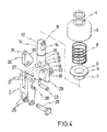
- figures 1 to 4 show the device in its first way of embodiment, being basically constituted by two aprts which may become independent from each other and which are generally referred to with numbers 1 and 2.
- Part 1 comprises an inverted housing 3 with a hole 4 in its base. Inside said housing-shaped piece 3 there is a disk piece 5 having a concentric hole 6 and extending into a cylindrical neck 7, an expansion spring 8 being located between the bottom of the housing 3 and the upper surface of the disk piece 5, as can be clearly seen in figure 2.
- the threee above described figures 3, 5 and 8 are crossed by an axial bolt 9 that extends through the hole 4 of the housing 3, thereby defining an outer portion 10 of said bolt 9.
- the emerging portion 10 has a transversal hole 11 wherein a pin 12 is located, said pin 12 being for the retention of a shackle 13 or the like, so that, through said shackle 13 the device is fastened to the anchor suspension chain of cable.
- the bolt 9 is provided with lateral facets 14 under which there is a step 15 defining a bigger diameter so as to abut against the bottom of the housing 3, such as it can be seen in figures 2 and 3.
- the lower end of said bolt 9 extends into an expansion 16 which having a general forked shape, said forked expansion 16 defining a projecting upper portion 17 whereagainst the lower edge of the cylindrical neck 7 of the disk piece 5 abuts, thereby avoiding that the push of the spring 8 makes said disk piece 5 escape with respect to the housing 3.
- Said forked expansion 16 is laterally wave-shaped, such as it can be seen in figure 4 and may be stepped or of any other adequate pattern, defining in any case a recess 18 from which an inclined ramp 19 is determined in an upward sense towards the bolt 9, said ramp 19 being located between the two branches of the forked expansion 16.
- Said forked expansion 16 in the face opposite to the one that defines the wavy pattern 18, is provided with a lug 20 with a hole, wherein the end of a small chain is fixed, whilst its other end is fixed to the lower part or base of the anchor.
- the second basic part 2 of the device is arranged on the forked expansion 16. Therefore, this part 2 is provided with two parallel wings 21 having respective facing holes, wherein a pin 23 serving as rotation axis for a pawl 24 is retained. Opposite to said wings 21 of part 2, this having another two end or lower wings 25 with passing holes, one of them being threaded, as shown in figure 4, for fixing a screw 26 provided for fixing said part 2 to the upper end of the anchor arm.
- the wings 21 of said part 2 have a projecting undulated portion 27 which is adapted to the shape of recess 18 of the forked expansion 16, so that positioning and adjustment of both parts with respect to each other is achieved.
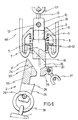
- Figures 5, 6 and 7 show a modification of the device defining a second embodiment thereof, said modification affecting the basic parts 1 and 2 of the assembly and the upper part of the housing-shaped piece 3.
- Said figures 5, 6 and 5 show how said housing 3 is provided around the hole 4 of its base with two pairs of concave cuts 32 and 33, perpendicular to each other, cuts 32 being of a bigger amplitude than cuts 33.
- Said cuts have been performed so that any size of shackle 13 can be used, through which shackle 13 the device assembly is coupled to the corresponding suspension chain or cable 57, so that, when said shackle 13 is of a big size, its concave lower part will be adapted to the larger cuts 32, whilst when the shackle is smaller in size, said lower and concave part will be adapted to the smaller cuts 33.
- Lug 20 is arranged for fixing one of the ends of the small chain 37, which will be fixed to the base of the anchor by its other end.
- Said part 2 has the peculiarity that the pawl 24 is a part, being provided with its corresponding lug 31 and with its inclined ramp 19 of the expansion 16 corresponding to the stem 9.
- the coupling of both parts is carried out just in the same way, but with the peculiarity that the coupling parts are prismatic pieces, the contact surfaces of which, according to an elevationval view are straight. Said prismatic pieces are easier to mechanize, with the peculiarity that the pawl 24 is not constituted by an independent and seesawing element, but it is part of piece 39.
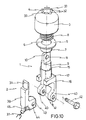
- FIGs 8, 9 and 10 show another embodiment with the peculiarity that in this case separable part 2 is articulated to the expansion 16 of the bolt 9 belonging to part 1.
- Said expansion 16 lacks an inclined ramp, there being defined in it, two parallel and lower arms 40 with respective passing holes 41 for the passing and fixing of a screw 42 that constitutes the articulation and seesawing axle of the piece 39 constituting said part 2 of the device, for which this piece 39 also lacks the inclined ramp or plane and the pawl.
- Part 2 comprises an upper lug 31, as well as, at its lower part, a projecting part 43 having a hole 44, facing holes 41 when positioned between the arms 40 to permit the screw 42 to pass through said holes 41 and 44 and constitute the articulation means between both parts 1, 2.
- piece 39 will not be separated from part 1, but, when actuating the device, it will seesaw so as to separate only the suspension chain or cable from the anchor.
- the small chain 37 that joins the device assembly to the lower base of the anchor is fixed to the heel 45 provided at the seesawing piece 39, whilst the ring 38 that attaches the upper part of the anchor to the device is arranged and retained between both said parts or pieces 16 and 39.
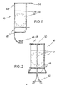
- any of the three embodiments of the device are complemented with an independent accessory element 46 as shown in figures 11, 12, 13, 14 and 15.
- Figures 11 and 12 correspond to an embodiment of said cage-shaped accessory element, whilst figure 13 corresponds to a second embodiment thereof and figures 14 and 15 to further alternative embodiments.
- the said independent accessory element 46 preferably comprises a series of rods 47 coupled to each other by means of annular rods 48, with the peculiarity that one of the longitudinal rods 47 extends by its lower part exceeding the length of the others in order to form a projection 49 in way of a hook of special configuration, i.e., without ends.
- the hook-like projection 49 is formed by both portions of bent rods that bend inwards and upwards without defining sharp ends, but a part to be adapted to the lower portion of the housing 3 and, specifically, for tractioning the disk piece 5, as it will be described hereinafter.
- Said accessory element 46 as shown in figures 11 and 12 has, in correspondence with the upper rod or ring 48 a radial appendix 50 attached to the end of a cable for tractioning said accessory element 46 described hereinafter.
- the accessory element or cage 46 corresponding to the embodiment shown in figure 13, is only formed by two longitudinal rods 47 which bend by their lower end into curvilinear shape 51 and which are attached to each other without break in continuity through an inwardly projected bent portion 52, having the same function as the aforementioned hook-like element 49 of the embodiment of figures 11 and 12.
- two turns 53 also being formed by both rods are welded, one of them in correspondence with the upper end and the other in correspondence with a part near the lower end, so that, through said turns 53, the suspension chain or cable of the device assembly and, consequently, of the anchor, can be inserted without difficulty.
- On the upper turn 53 is welded a rigid ring 54 that is arranged according to a horizontal plane, so that, through said ring 54 the accessory 46 is attached to a cable that will be handled by the operator in the boat, i.e., said ring 54 will accomplish the same function as the radial appendix 50 of the accessory element 46 corresponding to figures 11 and 12.
- the accessory element 46 of figure 13 is complemented with a rigid semi-ring 55 being welded between both rods 47 and arranged between the lower turn 53 and the lower part of the accessory element 46 such as shown in figure 13.
- Figure 14 shows another alternative form of the tractioning accessory element 46, which is also formed by two rods 47, the lower end of which is bent in order to define both lower portions tending to converge outwards. Between said portions is welded an especially shaped piece 59 defining the hook-like structure 49 that has been mentioned in connection with figures 11, 12 and 13. The turns or rings 60 are welded between said rods 47, in correspondence with the upper part and a zone near the lower part.
- Said rings 60 have a wide open portion wherein a band or the like 61 is fixed, which is deformed inwardly when pressed and allows inserting the anchor suspension chain or cable inside the accessory element 46, so that it may escape because said band 61 recovers its original position and closes said opening of the corresponding ring 60.
- Figure 15 shows another alternative of said accessory element 46, formed in this case by the rods 47 with their lower end being bent, said ends tending to converge outwards and the piece 59 constituting the tractioning hook being welded between them, all that such as in figure 14, but with the variant that in said figure 15 the rings are divided into two halves, one of them 62 being fixed between the rods 47 and the other one 63 being hinged at 64 to one of the rods 47, thereby enabling the accessory to open sideways for insertion of the anchor suspension chain or cable, said anchor being retained when closing again the half 63 of said rings, each half 63 being provided at its free end with attaching means 65 in order to avoid the accidental opening thereof.
- Figures 16 and 17 show schematically the operations to be carried out for releasing, by the device according to the invention, an anchor moored to the sea bottom.
- an anchor 56 appears retained in a crack.
- said anchor 56 is tractioned in the classical way, i.e., by means of a suspension chain or cable directly attached thereto, it is impossible to release said anchor, since, when tractioning the upper part thereof, the lug located in the crack is more and more stuck into it.
- the release of said anchor 56 is easily carried out with no difficulty at all.
- the device inserted between the ring 38 provided at the upper end of the anchor 56 arm and the lower end of the suspension chain or cable 57. That is to say, that instead of fixing directly the suspensiuon chain or cable 57 to the ring 38 of the anchor 56, the device according to the invention is inserted between said ring 38 of the anchor and the lower end of the suspension chain or cable 57.
- the small chain 37 which, in the case of the embodiments of the device corresponding to figures 1 to 4 and 5 to 7, is arranged between the lower base of the anchor and the expansion 16 corresponding to part 1, whilst according to the embodiment of figures 8 to 10, said chain 37 is arranged between the lower base of the anchor and the seesawing piece 39 and, specifically, fixed to the heel 45 of said piece.
- both parts constituting the device is carried out as previously described, i.e., positioning firstly the projection 28 of part 39 at the step 29 of the expansion 16, so that, once said step 29 and said projection 16 have been engaged, the disk piece 5 is tractioned upwards and both said pieces 16 and 39 are adapted with respect to each other, the disk piece 5 being then released so that the lug 31 stays inside the cylindrical body of said disk piece 5, both parts or pieces being thus retained with respect to each other.
- the anchor 56 is thereby suspended from the suspension chain or cable 57 under insertion of the assembled device.
- said accessory 46 is slided along the suspension chain or cable 57 and, due to the special configuration thereof and to the configuration of the device, the hook-like structure 49 of the accessory element 46 corresponding to figures 11 and 12, or the lower portion 52 of the accessory element 46 corresponding to figure 13, or the piece 59 of the accessory element 46 corresponding to figures 14 and 15, will be inserted over the lower part of the housing 3, such as shown for instance in figures 3, 6 and 9, and, consequently, said hook 49 or in its case the lower part 56 or 59 of said accessory element 46 will lean against the lower face of the disk piece 5.
- the boat will be made to advance to the position referred to with d in said figure 17, in order to traction then the suspension chain or cable 57, which, through the small chain 37, will traction the lower base of the anchor 56, which tractioning will be carried out in al almost opposite sense with respect to the direction of the attaching lug of said anchor, thereby releasing the latter, so as to raise finally all the assembly, the anchor included, on board the boat.
Landscapes
- Engineering & Computer Science (AREA)
- Combustion & Propulsion (AREA)
- Mechanical Engineering (AREA)
- Ocean & Marine Engineering (AREA)
- Chemical & Material Sciences (AREA)
- Bridges Or Land Bridges (AREA)
- Artificial Fish Reefs (AREA)
- Earth Drilling (AREA)
- Dowels (AREA)
- Non-Silver Salt Photosensitive Materials And Non-Silver Salt Photography (AREA)
- Hooks, Suction Cups, And Attachment By Adhesive Means (AREA)
- Underground Or Underwater Handling Of Building Materials (AREA)
- Catching Or Destruction (AREA)
- Revetment (AREA)
- Transmitters (AREA)
Claims (15)
Priority Applications (1)
| Application Number | Priority Date | Filing Date | Title |
|---|---|---|---|
| AT87108736T ATE60741T1 (de) | 1986-06-25 | 1987-06-18 | System zum loesen eines am meeresboden haftenden ankers. |
Applications Claiming Priority (4)
| Application Number | Priority Date | Filing Date | Title |
|---|---|---|---|
| ES556783A ES8704408A1 (es) | 1986-06-25 | 1986-06-25 | Sistema para liberar un ancla aferrado al fondo del mar |
| ES556783 | 1986-06-25 | ||
| ES557345 | 1987-01-21 | ||
| ES557345A ES557345A0 (es) | 1987-01-21 | 1987-01-21 | Sistemas para liberar un ancla aferrado al fondodel mar |
Publications (3)
| Publication Number | Publication Date |
|---|---|
| EP0254033A2 EP0254033A2 (fr) | 1988-01-27 |
| EP0254033A3 EP0254033A3 (en) | 1988-10-05 |
| EP0254033B1 true EP0254033B1 (fr) | 1991-02-06 |
Family
ID=26156161
Family Applications (1)
| Application Number | Title | Priority Date | Filing Date |
|---|---|---|---|
| EP87108736A Expired - Lifetime EP0254033B1 (fr) | 1986-06-25 | 1987-06-18 | Système pour relâcher une ancre fixe au fond de l'eau |
Country Status (8)
| Country | Link |
|---|---|
| US (1) | US4846093A (fr) |
| EP (1) | EP0254033B1 (fr) |
| AT (1) | ATE60741T1 (fr) |
| AU (1) | AU597988B2 (fr) |
| BR (1) | BR8703623A (fr) |
| CA (1) | CA1301560C (fr) |
| DE (1) | DE3767939D1 (fr) |
| NZ (1) | NZ220826A (fr) |
Families Citing this family (8)
| Publication number | Priority date | Publication date | Assignee | Title |
|---|---|---|---|---|
| JPS63315395A (ja) * | 1987-06-19 | 1988-12-23 | Satoru Kobayashi | アンカ−の根がかり解放装置 |
| JP2914696B2 (ja) * | 1990-02-10 | 1999-07-05 | 悟 小林 | アンカーの根がかり解放装置 |
| NL9202083A (nl) * | 1992-12-01 | 1994-07-01 | Vrijhof Ankers Beheer Bv | Ankervloei. |
| DE19635688C1 (de) * | 1996-09-03 | 1998-04-09 | Wilhelm Roesch | Anker mit Festhalten von Wasserfahrzeugen |
| US5784981A (en) * | 1996-09-17 | 1998-07-28 | Graham, Sr.; Leonard R. | V-shaped retrievable anchor |
| US6811113B1 (en) * | 2000-03-10 | 2004-11-02 | Sky Calypso, Inc. | Internet linked environmental data collection system and method |
| GB2434409A (en) * | 2006-01-24 | 2007-07-25 | William Kingston | Tidal energy system |
| US7870831B2 (en) * | 2008-06-23 | 2011-01-18 | David Richert | Anchor with snag release mechanism |
Family Cites Families (9)
| Publication number | Priority date | Publication date | Assignee | Title |
|---|---|---|---|---|
| US2490460A (en) * | 1948-07-09 | 1949-12-06 | Theodore E Mcavoy | Retrievable anchor means |
| US2669962A (en) * | 1950-07-06 | 1954-02-23 | Dovie A Harrison | Antifouling anchor |
| FR2172603A5 (fr) * | 1972-02-16 | 1973-09-28 | Martinez Georges | |
| US3809001A (en) * | 1972-07-31 | 1974-05-07 | A Shute | Device for freeing a fouled anchor |
| AU7706174A (en) * | 1974-01-17 | 1976-07-01 | Petersen G R | Anchor |
| AU7785075A (en) * | 1974-02-28 | 1976-08-05 | Bean R J | Boat anchor |
| IT1195800B (it) * | 1982-06-28 | 1988-10-27 | Carlo Pedruzzi | Dispositivo per un semplice e rapido disincaglio di strumenti pesanti incattivati nel fondale marino,quali ad esempio ancore |
| NL8500719A (nl) * | 1985-03-13 | 1986-10-01 | Haak Rob Van Den | Inrichting voor het uitbrengen en lichten van ankers. |
| JPS61275085A (ja) * | 1985-05-30 | 1986-12-05 | Satoru Kobayashi | 船舶のアンカ−装置 |
-
1987
- 1987-06-18 US US07/064,196 patent/US4846093A/en not_active Expired - Fee Related
- 1987-06-18 AT AT87108736T patent/ATE60741T1/de not_active IP Right Cessation
- 1987-06-18 EP EP87108736A patent/EP0254033B1/fr not_active Expired - Lifetime
- 1987-06-18 DE DE8787108736T patent/DE3767939D1/de not_active Expired - Lifetime
- 1987-06-23 AU AU74631/87A patent/AU597988B2/en not_active Ceased
- 1987-06-23 CA CA000540321A patent/CA1301560C/fr not_active Expired - Lifetime
- 1987-06-24 NZ NZ220826A patent/NZ220826A/xx unknown
- 1987-06-25 BR BR8703623A patent/BR8703623A/pt unknown
Also Published As
| Publication number | Publication date |
|---|---|
| EP0254033A2 (fr) | 1988-01-27 |
| AU597988B2 (en) | 1990-06-14 |
| ATE60741T1 (de) | 1991-02-15 |
| CA1301560C (fr) | 1992-05-26 |
| DE3767939D1 (de) | 1991-03-14 |
| US4846093A (en) | 1989-07-11 |
| NZ220826A (en) | 1989-10-27 |
| AU7463187A (en) | 1988-01-07 |
| BR8703623A (pt) | 1988-03-22 |
| EP0254033A3 (en) | 1988-10-05 |
Similar Documents
| Publication | Publication Date | Title |
|---|---|---|
| EP0254033B1 (fr) | Système pour relâcher une ancre fixe au fond de l'eau | |
| AU631526B2 (en) | Tensioning device | |
| KR960001842B1 (ko) | 앵커 회수장치 | |
| US7870831B2 (en) | Anchor with snag release mechanism | |
| AU598844B2 (en) | Apparatus for lifting concrete panels | |
| EP0202121B1 (fr) | Attache à manoeuvre manuelle | |
| US20220106019A1 (en) | Releasable mooring chain link | |
| JP4545853B2 (ja) | アンカー回収装置 | |
| US4987654A (en) | Dual-release fastener for strap ends | |
| EP0328884B1 (fr) | Utensile de pêche | |
| US20100050918A1 (en) | Anchor Retrieval System (ARS) | |
| JP3163169U (ja) | 錨用フックおよびそれを備えた錨 | |
| EP0102464B1 (fr) | Dispositif pour le renflouage rapide et aisé d'ancres étant immobilisés dans le sol marin | |
| JPS6368483A (ja) | 海底に係留したアンカーを解放する装置 | |
| US6035798A (en) | Marine anchor | |
| US4200053A (en) | Mooring cinch | |
| EP3931463B1 (fr) | Liaison de chaîne d'amarrage libérable | |
| US20120048167A1 (en) | Mooring device for boats | |
| JP2636173B2 (ja) | 小型アンカ | |
| US3235927A (en) | Catenary cable link | |
| EP0057221A1 (fr) | Crochet permettant d'attacher un utilisateur a une planche a voile | |
| US20210387707A1 (en) | Anchor Rescue System | |
| JP2010036614A (ja) | 錨用フックおよびそれを備えた錨 | |
| NO20211320A1 (en) | A magnet activatable release apparatus, an assembly comprising the apparatus, and a method of using the assembly | |
| JP2004345614A (ja) | 船舶等の係留用器具 |
Legal Events
| Date | Code | Title | Description |
|---|---|---|---|
| PUAI | Public reference made under article 153(3) epc to a published international application that has entered the european phase |
Free format text: ORIGINAL CODE: 0009012 |
|
| AK | Designated contracting states |
Kind code of ref document: A2 Designated state(s): AT BE CH DE FR GB GR IT LI LU NL SE |
|
| PUAL | Search report despatched |
Free format text: ORIGINAL CODE: 0009013 |
|
| RHK1 | Main classification (correction) |
Ipc: B63B 21/46 |
|
| AK | Designated contracting states |
Kind code of ref document: A3 Designated state(s): AT BE CH DE FR GB GR IT LI LU NL SE |
|
| 17P | Request for examination filed |
Effective date: 19881108 |
|
| 17Q | First examination report despatched |
Effective date: 19890808 |
|
| GRAA | (expected) grant |
Free format text: ORIGINAL CODE: 0009210 |
|
| AK | Designated contracting states |
Kind code of ref document: B1 Designated state(s): AT BE CH DE FR GB GR IT LI LU NL SE |
|
| PG25 | Lapsed in a contracting state [announced via postgrant information from national office to epo] |
Ref country code: SE Effective date: 19910206 Ref country code: BE Effective date: 19910206 Ref country code: AT Effective date: 19910206 |
|
| REF | Corresponds to: |
Ref document number: 60741 Country of ref document: AT Date of ref document: 19910215 Kind code of ref document: T |
|
| REF | Corresponds to: |
Ref document number: 3767939 Country of ref document: DE Date of ref document: 19910314 |
|
| ITF | It: translation for a ep patent filed | ||
| ET | Fr: translation filed | ||
| PG25 | Lapsed in a contracting state [announced via postgrant information from national office to epo] |
Ref country code: LU Free format text: LAPSE BECAUSE OF NON-PAYMENT OF DUE FEES Effective date: 19910630 |
|
| PLBE | No opposition filed within time limit |
Free format text: ORIGINAL CODE: 0009261 |
|
| STAA | Information on the status of an ep patent application or granted ep patent |
Free format text: STATUS: NO OPPOSITION FILED WITHIN TIME LIMIT |
|
| 26N | No opposition filed | ||
| REG | Reference to a national code |
Ref country code: GR Ref legal event code: FG4A Free format text: 3001906 |
|
| PGFP | Annual fee paid to national office [announced via postgrant information from national office to epo] |
Ref country code: CH Payment date: 19930628 Year of fee payment: 7 |
|
| PGFP | Annual fee paid to national office [announced via postgrant information from national office to epo] |
Ref country code: NL Payment date: 19930630 Year of fee payment: 7 |
|
| PG25 | Lapsed in a contracting state [announced via postgrant information from national office to epo] |
Ref country code: LI Effective date: 19940630 Ref country code: CH Effective date: 19940630 |
|
| PG25 | Lapsed in a contracting state [announced via postgrant information from national office to epo] |
Ref country code: NL Effective date: 19950101 |
|
| NLV4 | Nl: lapsed or anulled due to non-payment of the annual fee | ||
| REG | Reference to a national code |
Ref country code: CH Ref legal event code: PL |
|
| PGFP | Annual fee paid to national office [announced via postgrant information from national office to epo] |
Ref country code: GB Payment date: 19950614 Year of fee payment: 9 |
|
| PGFP | Annual fee paid to national office [announced via postgrant information from national office to epo] |
Ref country code: GR Payment date: 19950621 Year of fee payment: 9 |
|
| PGFP | Annual fee paid to national office [announced via postgrant information from national office to epo] |
Ref country code: DE Payment date: 19950627 Year of fee payment: 9 |
|
| PGFP | Annual fee paid to national office [announced via postgrant information from national office to epo] |
Ref country code: FR Payment date: 19950628 Year of fee payment: 9 |
|
| PG25 | Lapsed in a contracting state [announced via postgrant information from national office to epo] |
Ref country code: GB Effective date: 19960618 |
|
| PG25 | Lapsed in a contracting state [announced via postgrant information from national office to epo] |
Ref country code: GR Free format text: THE PATENT HAS BEEN ANNULLED BY A DECISION OF A NATIONAL AUTHORITY Effective date: 19961231 |
|
| REG | Reference to a national code |
Ref country code: GR Ref legal event code: MM2A Free format text: 3001906 |
|
| GBPC | Gb: european patent ceased through non-payment of renewal fee |
Effective date: 19960618 |
|
| PG25 | Lapsed in a contracting state [announced via postgrant information from national office to epo] |
Ref country code: FR Effective date: 19970228 |
|
| PG25 | Lapsed in a contracting state [announced via postgrant information from national office to epo] |
Ref country code: DE Effective date: 19970301 |
|
| REG | Reference to a national code |
Ref country code: FR Ref legal event code: ST |
|
| PG25 | Lapsed in a contracting state [announced via postgrant information from national office to epo] |
Ref country code: IT Free format text: LAPSE BECAUSE OF NON-PAYMENT OF DUE FEES;WARNING: LAPSES OF ITALIAN PATENTS WITH EFFECTIVE DATE BEFORE 2007 MAY HAVE OCCURRED AT ANY TIME BEFORE 2007. THE CORRECT EFFECTIVE DATE MAY BE DIFFERENT FROM THE ONE RECORDED. Effective date: 20050618 |