EP0254058A2 - Arbre à cames pour le réglage des soupapes d'admission et d'échappement d'un moteur à combustion interne - Google Patents
Arbre à cames pour le réglage des soupapes d'admission et d'échappement d'un moteur à combustion interne Download PDFInfo
- Publication number
- EP0254058A2 EP0254058A2 EP87109060A EP87109060A EP0254058A2 EP 0254058 A2 EP0254058 A2 EP 0254058A2 EP 87109060 A EP87109060 A EP 87109060A EP 87109060 A EP87109060 A EP 87109060A EP 0254058 A2 EP0254058 A2 EP 0254058A2
- Authority
- EP
- European Patent Office
- Prior art keywords
- shaft
- adjusting device
- outer shaft
- disk
- guide
- Prior art date
- Legal status (The legal status is an assumption and is not a legal conclusion. Google has not performed a legal analysis and makes no representation as to the accuracy of the status listed.)
- Granted
Links
Images



Classifications
-
- F—MECHANICAL ENGINEERING; LIGHTING; HEATING; WEAPONS; BLASTING
- F01—MACHINES OR ENGINES IN GENERAL; ENGINE PLANTS IN GENERAL; STEAM ENGINES
- F01L—CYCLICALLY OPERATING VALVES FOR MACHINES OR ENGINES
- F01L1/00—Valve-gear or valve arrangements, e.g. lift-valve gear
- F01L1/34—Valve-gear or valve arrangements, e.g. lift-valve gear characterised by the provision of means for changing the timing of the valves without changing the duration of opening and without affecting the magnitude of the valve lift
- F01L1/344—Valve-gear or valve arrangements, e.g. lift-valve gear characterised by the provision of means for changing the timing of the valves without changing the duration of opening and without affecting the magnitude of the valve lift changing the angular relationship between crankshaft and camshaft, e.g. using helicoidal gear
- F01L1/34413—Valve-gear or valve arrangements, e.g. lift-valve gear characterised by the provision of means for changing the timing of the valves without changing the duration of opening and without affecting the magnitude of the valve lift changing the angular relationship between crankshaft and camshaft, e.g. using helicoidal gear using composite camshafts, e.g. with cams being able to move relative to the camshaft
-
- F—MECHANICAL ENGINEERING; LIGHTING; HEATING; WEAPONS; BLASTING
- F01—MACHINES OR ENGINES IN GENERAL; ENGINE PLANTS IN GENERAL; STEAM ENGINES
- F01L—CYCLICALLY OPERATING VALVES FOR MACHINES OR ENGINES
- F01L1/00—Valve-gear or valve arrangements, e.g. lift-valve gear
- F01L1/02—Valve drive
- F01L1/04—Valve drive by means of cams, camshafts, cam discs, eccentrics or the like
- F01L1/047—Camshafts
- F01L2001/0471—Assembled camshafts
- F01L2001/0473—Composite camshafts, e.g. with cams or cam sleeve being able to move relative to the inner camshaft or a cam adjusting rod
Definitions
- the invention relates to an adjusting device for a camshaft for controlling the gas intake and exhaust valves of internal combustion engines with variable control times for opening and closing the valves.
- a positionally adjustable camshaft is known from the publication entitled “Variable valve control from Fiat” by Andrea Titolo in the magazine MTZ 47 (1986) No. 5, pages 185-188, with which the timing for opening and closing the valves can be changed are.
- the control times are changed by axial displacement, whereby the individual control cams must have a conical outer jacket.
- sliding pieces designed as rockers must be used between the tappet and control cams. The use of such sliders results in a complicated and wear-prone connection between the control cam and valve tappet.
- the axial displacement of the camshaft requires a complicated adjustment mechanism.
- the object of the invention is to change the control times of the gas inlet and outlet valves by a different design to achieve a camshaft also provided with a different adjustment mechanism.
- the angular position of the control cams controlling the exhaust valves on the one hand and the intake valves on the other hand can be changed in a simple manner relative to one another.
- the change can be achieved on the one hand by the fact that the angular position can be set to different values when the motor is at rest, or by the fact that the adjusting device is part of a control circuit by which the angular position between the control cams which are movable relative to one another depends on the prevailing motor operating data certain specifiable values is regulated.
- the camshaft consists of a hollow outer shaft 1 and a hollow inner shaft 3 mounted therein via bearings 2.
- Control cams 5 for either the intake or exhaust valves are shrunk on the outer shaft 1.
- the control cams 4 for the intake and exhaust valves, which are not actuated by the control cams 5, are rotatably mounted on the outer shaft 1 and are fixedly connected to the inner shaft 3 via a pin 7 projecting through a slot 6 in the outer shaft.
- Radial bores 8 and 9 are provided in the outer shaft 1 for lubricating the bearings 2 in the annular space between the outer shaft 1 and the inner shaft 3.
- the bores 9 each lie in areas in which the camshaft is supported via the outer shaft 1 on the internal combustion engine, of which it is a component, and serve to admit lubricating oil into the annular space. Through the holes 8, which are outside the bearing areas, the lubricating oil can leave the annular space again.
- an adjusting device 10 is provided with which the outer and inner shafts 1, 3 can be rotated relative to one another.
- the adjustment device is constructed as follows:
- a flange 11 is firmly attached to the end of the outer shaft.
- the inner shaft 3 projects beyond the end of the outer shaft and the flange 11 connected to it.
- a disc 12 which is axially spaced from the flange 11.
- An externally toothed gear 13 is rotatably mounted on the inner shaft between the flange 11 and the disk 12.
- the camshaft is driven by the crankshaft by means of a toothed belt.
- three slots 14 are provided in the same circumference on the same circumference. Through these slots 14 engage bolts 15 through which the flange 11 and the washer 12 are non-rotatably connected.
- the gear 13 serves as a planet carrier for planet gears 16 of a planetary gear.
- the planet gears 16, which are mounted on bearing journals 17 in the gear 13, are located axially between the gear 13 and the disk 12.
- the planet gears 16 are driven by a sun gear 18, which is fixedly connected to the inner shaft 3.
- Radially on the outside, the planetary gears 16 mesh in a ring gear 19 fixedly connected to the disk 12.
- the flange 11, the gear 13 and the disk 12 can be non-positively connected to the ring 20 via a nut 20 engaging the end of the inner shaft 3. Given by the tightened nut 20 a positive connection of the aforementioned parts, the toothed belt coming from the crankshaft drives the camshaft via the gearwheel 13, specifically the outer and inner shafts 1, 3 with a rigid connection to one another.
- the adjusting device 10 is as follows to operate.
- the nut 20 is loosened when the inner shaft 3 is also locked in the circumferential direction, so that the non-positive connection between the disk 12 with the ring gear 19, the gear 13 and the flange 11 is canceled.
- the inner shaft 3 With the circumferential position of the gear 13 still locked, the inner shaft 3 is rotated. In order to be able to turn or lock the inner shaft 3 in the circumferential direction, it is provided at its end with a gripping cam 21 for attaching a tool key.
- the sun gear 18, which is fixedly connected to the inner shaft 3 causes the planetary gears 16 to rotate, which in turn, via the ring gear 19, rotate the disk 12, which is firmly connected to the ring gear 19.
- the flange 11 fixedly attached to the outer shaft 1 is non-rotatably connected. The outer shaft is thus rotated to the same extent as the disk 12.
- the choice of the transmission ratio in the planetary gear can determine to what extent the outer shaft is rotated in the opposite direction when the inner shaft is rotated in one direction.
- the gear ratio can be set so that the inner and outer shafts 3, 1 are adjusted by the same angle of rotation in opposite directions. After mutual twisting of the inside and outside shaft 3, 1, the nut 20 is again tightened with the locked inner shaft 3 and locked gear 13 to produce a non-positive connection between the parts 11, 13 and 12.
- the inner shaft 3 is secured against sliding into the outer shaft 1 via an annular disk 22 screwed to it.
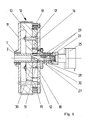
- an electric stepper motor 23 is flanged to the disk 12.
- the output shaft 24 of this stepper motor is rigidly connected to the inner shaft 3 of the camshaft. If the angular position between the control cams 4 and 5 is to remain unchanged during motor operation, the stepper motor is controlled electrically so that it alternately exerts control pulses which rotate in opposite directions on the inner shaft 3, with the result that, with a sufficiently high pulse frequency, practically a rigid connection between the outer and inner shaft 1, 3 is given.
- the stepper motor 23 only has to be controlled so that the output shaft 24 is rotated.
- the planetary gear which corresponds to that of the adjusting device according to FIGS. 1 and 2, can be used to determine the extent to which the control cams 4, 5 are rotated relative to one another by the fixed transmission ratio.
- the translation ver Ratio in particular be chosen such that both types of control cams are adjusted by the same amount in opposite directions.
- the control current for the stepper motor is fed to it via sliding contacts.
- the stepper motor can be controlled via parameters dependent on specific motor operating states, as a result of which certain angular positions of the control cams 4, 5 can be set or regulated in relation to specific motor operating conditions.
- a change in the angular position of the control cams 4, 5 depending on the engine operation is also possible with the adjusting devices to be described below.
- a hydraulic motor 25 fixedly attached to the internal combustion engine is used.
- a bolt 27 is rotatably axially fixed.
- This bolt 27 projects axially into the inner shaft 3, the inner shaft 3 and the bolt 27 being rotatable and displaceable relative to one another.
- the bolt 27 is at the same time in a flange 28 fixedly connected to the disk 12 stores in which it is longitudinally displaceable but not rotatable.
- the bolt 27 is secured against rotation by a tongue and groove connection 29 between the bolt 27 and the flange 28.
- a spindle groove 30 is formed in the bolt 27, into which a ball 31 which is fixedly mounted in the inner shaft 3 engages.
- a compression spring 32 engages, which loads the punch 26 in the direction away from the flange 28.
- the inner shaft 3 is rotated via the ball 31 sliding in the spindle groove 30.
- the same angular position adjustment of the control cams 4, 5 can be achieved with the hydraulic motor 25 during motor operation as with the stepper motor 23 in the adjusting device according to FIG. 5.
- the same control pulses can be supplied to the hydraulic motor 25 as the stepper motor.
- the change in the angular position between the control cams 4, 5 is also adjustable during engine operation as a function of the engine operating data.
- this embodiment does not use a planetary gear.
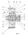
- the adjustment device according to FIG. 7 is constructed in detail as follows.
- a flange 11 is fixedly mounted on the outer shaft 1.
- a disk 12 is rigidly connected to the inner shaft 3 at an axial distance from the flange 11.
- the rigid connection of the disk 12 to the inner shaft 3 takes place via a shaft stub 33 fixedly mounted on the end of the inner shaft 3.
- a guide disk 34 is rotatably mounted on the stub shaft 33 and can be rotated against the flange 11 and the disk 12.
- An externally toothed gear 35 is fastened to the guide disk 34 by means of screws 36.
- guide pieces 37 arranged in a radially movable manner are used in the guide disk 34.
- These guide pieces 37 are cylindrical bodies which can be displaced in a radial bore 38.
- the bores 38 are closed radially on the outside. Radially on the inside, the bores 38 can be acted upon by hydraulic oil, which enters the bores 38 from a pressure source via a ring connection 39 fixedly mounted on the internal combustion engine through the stub shaft 33, which is rotatably supported in the ring connection 39.
- the guide slots 41, 42 must be in one direction run, which lies between a diametrical alignment on the one hand and an alignment in the circumferential direction on the other. This is the only way to rotate the flange 11 or the disk 12 in which they are arranged. If both shafts are not to be rotated at the same time, but rather only one shaft or one shaft is to be adjusted first and the other only subsequently, the guide slot in the flange 11 or the disk 12, in particular in the disk 12, can also be at least partially aligned diametrically.
- the gear 35 by means of which the camshaft is driven by the crankshaft with the aid of a timing belt, transmits the driving forces to the flange 11 and the disk 12 via the driving pins 40. Since the camshaft is supported by the outer shaft 1, it must be carried out on the flange 11 attacking driving pins 40 are transmitted a greater driving torque than by engaging in the disc 12 Driving pins 40. The radial position which the guide pieces 37 assume from the radial inside due to the driving pins 40 and the hydraulic loading is thus determined by the guidance of the driving pin 40 in the flange 11.
- a force plan entered in FIG. 8 with regard to the transmission of force in the guide slot 41 clearly shows the restoring force acting radially inwards on the guide pieces 37.
- F U represents the circumferential force emanating from the driver on the flange 11.
- this circumferential force is divided into two components, namely a normal force F N acting on the slot path and a force F S acting in the longitudinal direction of the slot.
- the force F S causes the guide piece 37 to move radially inward in the direction of rotation of the flange 12 shown in FIG. 8 when there is no hydraulic counterforce. In this consideration, it has initially been disregarded that a centrifugal force counter to the force F S also acts on the guide pieces 37.
- Frictional forces between the driver and the guideway have also been disregarded. If these opposing forces are taken into account, in order to ensure a radially inward movement of the guide pieces, only the force F S has to be greater than the counter forces mentioned, which is regularly the case in practice for camshafts for internal combustion engines.
- Fig. 9 shows the arrangement of the guide slot 42 in the disc 12. Taking into account the direction of rotation of the disc 12 shown in Fig. 9, it can be seen that the guide slot 42 with respect to the direction of rotation of the camshaft has an opposite inclination with respect to the guide slot 41.
- control cams 4 and 5 are rotated by the same amount in opposite directions.
- the course and the interdependency of the timing of the cams 4 and 5 can be varied as desired by different positions and shapes of the guide slots.
- the hydraulic pressure for adjusting and controlling the guide body 37 is determined by a processor on the basis of measured engine operating data.
- the processor emits a proportional current via a power unit, which is used to control an adjustable pressure relief valve with the aid of a proportional magnet.
- the pressure released by the pressure limiting valve on the hydraulic fluid then acts on the guide pieces 37.
- the hydraulic fluid passes through an annular channel 44 in a cap 45 attached to the stub shaft 33, a blind hole 46 in the stub shaft 33, a through hole 47 also in the stub shaft 33, a further ring channel 48 and an inlet hole 49 leading into the hole 38.
Landscapes
- Engineering & Computer Science (AREA)
- Mechanical Engineering (AREA)
- General Engineering & Computer Science (AREA)
- Valve Device For Special Equipments (AREA)
- Valve-Gear Or Valve Arrangements (AREA)
Applications Claiming Priority (2)
| Application Number | Priority Date | Filing Date | Title |
|---|---|---|---|
| DE19863624827 DE3624827A1 (de) | 1986-07-23 | 1986-07-23 | Verstelleinrichtung fuer eine nockenwelle zum steuern der gasein- und auslassventile von verbrennungsmotoren |
| DE3624827 | 1986-07-23 |
Publications (3)
| Publication Number | Publication Date |
|---|---|
| EP0254058A2 true EP0254058A2 (fr) | 1988-01-27 |
| EP0254058A3 EP0254058A3 (en) | 1989-08-09 |
| EP0254058B1 EP0254058B1 (fr) | 1992-09-16 |
Family
ID=6305751
Family Applications (1)
| Application Number | Title | Priority Date | Filing Date |
|---|---|---|---|
| EP87109060A Expired - Lifetime EP0254058B1 (fr) | 1986-07-23 | 1987-06-24 | Arbre à cames pour le réglage des soupapes d'admission et d'échappement d'un moteur à combustion interne |
Country Status (2)
| Country | Link |
|---|---|
| EP (1) | EP0254058B1 (fr) |
| DE (2) | DE3624827A1 (fr) |
Cited By (25)
| Publication number | Priority date | Publication date | Assignee | Title |
|---|---|---|---|---|
| FR2649443A1 (fr) * | 1989-07-04 | 1991-01-11 | Gkn Automotive Ag | Arbre a cames composite, a elements emboites dont le calage angulaire peut etre modifie |
| DE3921923A1 (de) * | 1989-07-04 | 1991-01-17 | Gkn Automotive Ag | Nockenwelle |
| EP0367192B1 (fr) * | 1988-10-29 | 1996-01-03 | Mazda Motor Corporation | Dispositif d'entraînement de soupape pour moteur à combustion interne |
| EP0686754A3 (fr) * | 1994-05-12 | 1996-04-10 | Carraro Spa | Dispositif de distribution à arbre unique, en particulier pour moteurs à combustion interne |
| EP0918142A3 (fr) * | 1997-11-21 | 1999-07-14 | Mazda Motor Corporation | Dispositif pour le contrÔle de la phase angulaire |
| DE4110195C2 (de) * | 1991-03-28 | 2000-02-10 | Schaeffler Waelzlager Ohg | Verstellvorrichtung für eine Nockenwelle |
| EP1043482A3 (fr) * | 1999-03-23 | 2001-09-05 | TCG UNITECH Aktiengesellschaft | Déphaseur d'arbre à cames pour moteur à combustion interne |
| FR2843997A1 (fr) | 2002-08-29 | 2004-03-05 | Renault Sa | Systeme de distribution a calage et etalement variable pour la commande des soupapes d'un moteur a combustion interne |
| WO2005103455A1 (fr) * | 2004-04-20 | 2005-11-03 | Daimlerchrysler Ag | Mecanisme de reglage conçu pour un ensemble arbre a cames |
| WO2006050686A1 (fr) * | 2004-11-09 | 2006-05-18 | Mahle Ventiltrieb Gmbh | Support entre deux arbres a cames coaxiaux destine notamment a des moteurs de vehicules automobiles |
| GB2424258A (en) * | 2005-03-18 | 2006-09-20 | Mechadyne Plc | Camshaft to phaser coupling |
| EP1726789A1 (fr) * | 2005-03-16 | 2006-11-29 | Mechadyne plc | Arbre à cames assemblé |
| WO2007007168A1 (fr) * | 2005-07-13 | 2007-01-18 | Toyota Jidosha Kabushiki Kaisha | Systeme de soupapes a distribution variable pour moteur a combustion interne |
| WO2007052075A1 (fr) * | 2005-11-02 | 2007-05-10 | Mechadyne Plc | Arbre a cames |
| WO2010054915A1 (fr) * | 2008-11-12 | 2010-05-20 | Zf Friedrichshafen Ag | Système de réglage pour arbres à cames d'un moteur à combustion interne |
| US8186319B2 (en) | 2007-07-02 | 2012-05-29 | Borgwarner Inc. | Concentric cam with check valves in the spool for a phaser |
| DE102011120815A1 (de) | 2011-12-10 | 2013-06-13 | Volkswagen Aktiengesellschaft | Verstellbarer Nockenwellenantrieb |
| US8584634B2 (en) | 2008-09-19 | 2013-11-19 | Borgwarner Inc. | Phaser built into a camshaft or concentric camshafts |
| US8893678B2 (en) | 2009-07-28 | 2014-11-25 | Daimler Ag | Valve drive arrangement |
| WO2015078588A1 (fr) * | 2013-11-29 | 2015-06-04 | Thyssenkrupp Presta Teccenter Ag | Arbre à cames réglable |
| DE102014112464A1 (de) | 2014-08-29 | 2016-03-03 | Thyssenkrupp Presta Teccenter Ag | Verstelleinheit für eine Nockenwelle einer Brennkraftmaschine |
| EP3176392A1 (fr) * | 2015-12-02 | 2017-06-07 | Mahle International GmbH | Arbre à cames réglable |
| WO2018050364A1 (fr) | 2016-09-19 | 2018-03-22 | Robert Bosch Gmbh | Déphaseur d'un arbre à cames à protection contre les défaillances |
| WO2018206192A1 (fr) | 2017-05-10 | 2018-11-15 | Robert Bosch Gmbh | Déphaseur d'arbre à cames ainsi qu'arbre à cames et moteur à combustion interne comprenant un déphaseur d'arbre à cames de ce type |
| FR3109797A1 (fr) * | 2020-04-29 | 2021-11-05 | Renault | Arbre à cames à paliers internes. |
Families Citing this family (24)
| Publication number | Priority date | Publication date | Assignee | Title |
|---|---|---|---|---|
| DE3937628A1 (de) * | 1989-11-11 | 1991-05-16 | Audi Ag | Antriebsvorrichtung fuer eine im zylinderkopf einer brennkraftmaschine gelagerten nockenwelle |
| DE3943426C1 (fr) * | 1989-12-22 | 1991-04-11 | Gkn Automotive Ag, 5200 Siegburg, De | |
| DE3943427C1 (fr) * | 1989-12-22 | 1991-04-04 | Gkn Automotive Ag, 5200 Siegburg, De | |
| DE4230074A1 (de) * | 1992-09-09 | 1994-03-10 | Bayerische Motoren Werke Ag | Hubkolben-Brennkraftmaschine mit zwei Gaswechselventilen je Zylinder |
| DE4306606A1 (de) * | 1993-03-03 | 1994-09-08 | Bayerische Motoren Werke Ag | Hubkolben-Brennkraftmaschine mit einer Nockenwellen-Antriebsverstelleinheit |
| US5823152A (en) * | 1995-06-14 | 1998-10-20 | Nippondenso Co., Ltd. | Control apparatus for varying a rotational or angular phase between two rotational shafts, preferably applicable to a valve timing control apparatus for an internal combustion engine |
| DE19733322A1 (de) * | 1997-08-01 | 1999-02-04 | Mwp Mahle J Wizemann Pleuco Gm | Ventilsteuerung einer als Antrieb oder Bremse schaltbaren Brennkraftmaschine |
| CH694812A5 (de) * | 2000-08-18 | 2005-07-29 | Karl Merz | Nockenwellenanordnung mit zwei gegeneinander verstellbaren Nockenwellen |
| DE10054796A1 (de) * | 2000-11-04 | 2002-06-13 | Ina Schaeffler Kg | Vorrichtung zur Drehwinkelverstellung einer Welle gegenüber ihrem Antrieb |
| DE102004020124A1 (de) * | 2004-04-24 | 2005-11-17 | Aft Atlas Fahrzeugtechnik Gmbh | Vorrichtung zur Einstellung von Ventilsteuerzeiten sowie Brennkraftmaschine mit einer derartigen Vorrichtung |
| DE102005014680A1 (de) * | 2005-02-03 | 2006-08-10 | Mahle International Gmbh | Nockenwelle mit gegeneinander verdrehbaren Nocken für insbesondere Kraftfahrzeuge |
| DE102005004976A1 (de) * | 2005-02-04 | 2006-08-10 | Mahle International Gmbh | Nockenwelle mit gegeneinander verdrehbaren Nocken für insbesondere Kraftfahrzeugmotoren |
| DE102006028611B4 (de) | 2006-06-22 | 2014-12-31 | Mahle International Gmbh | Verstellbare Nockenwelle |
| DE202006020694U1 (de) * | 2006-09-07 | 2009-06-18 | Mahle International Gmbh | Verstellbare Nockenwelle |
| DE102007042053A1 (de) * | 2007-09-05 | 2009-03-12 | Mahle International Gmbh | Kolbenmotor |
| US7841311B2 (en) | 2008-01-04 | 2010-11-30 | Hilite International Inc. | Variable valve timing device |
| DE102008033230B4 (de) | 2008-01-04 | 2010-05-27 | Hydraulik-Ring Gmbh | Doppelter Nockenwellenversteller in Schichtaufbau |
| DE102008023098A1 (de) | 2008-05-09 | 2009-12-17 | Hydraulik-Ring Gmbh | Doppelter Nockenwellenversteller in Schichtaufbau |
| US8113163B2 (en) | 2009-03-09 | 2012-02-14 | GM Global Technology Operations LLC | Concentric camshaft and method of assembly |
| DE102010033296A1 (de) | 2010-08-04 | 2012-02-09 | Hydraulik-Ring Gmbh | Nockenwellenversteller, insbesondere mit Nockenwelle |
| DE102011001301B4 (de) | 2011-03-16 | 2017-09-21 | Hilite Germany Gmbh | Schwenkmotorversteller |
| US9366159B2 (en) * | 2011-03-30 | 2016-06-14 | Borgwarner, Inc. | Concentric camshaft phaser torsional drive mechanism |
| DE102012220652A1 (de) | 2012-11-13 | 2014-05-15 | Mahle International Gmbh | Nockenwelle |
| DE102013216567A1 (de) * | 2013-08-21 | 2015-02-26 | Mahle International Gmbh | Ausrichtvorrichtung |
Family Cites Families (16)
| Publication number | Priority date | Publication date | Assignee | Title |
|---|---|---|---|---|
| DE144450C (fr) * | ||||
| DE446744C (de) * | 1927-07-11 | Siemens Schuckertwerke G M B H | Vorrichtung zur mechanischen UEbertragung einer Bewegung von einem relativ feststehenden auf einen relativ bewegten Koerper | |
| DE254135C (de) * | 1910-11-01 | 1912-11-23 | Ruthardt & Co | Federlose, regelnde kupplung für eine treibende und eine konachsiale getriebene welle |
| GB191500889A (en) * | 1914-01-26 | 1915-12-30 | Ferruccio Valobra | Differential Gear Control for Distributing Mechanisms in Reciprocating Engines. |
| GB154543A (en) * | 1919-11-26 | 1921-12-29 | Louis Damblanc | Improvements in and relating to transmission of movement |
| US1527456A (en) * | 1924-02-29 | 1925-02-24 | Woydt Edward | Valve-operating means |
| FR593322A (fr) * | 1925-01-06 | 1925-08-20 | Dispositif différentiel, permettant la mise au point, l'avance ou le retard, de l'admission, de l'allumage et de l'échappement dans les moteurs à explosion | |
| US1957181A (en) * | 1932-02-27 | 1934-05-01 | Edward W Mitchel | Automatic valve timing device |
| US3416502A (en) * | 1965-04-22 | 1968-12-17 | Weiss Joseph | Internal combustion engines |
| US3516394A (en) * | 1968-07-16 | 1970-06-23 | Roy G Nichols | Device for simultaneously advancing intake cam lobes and retarding exhaust cam lobes of an internal combustion engine while the engine is running |
| DE2822147C3 (de) * | 1978-05-20 | 1982-02-11 | Volkswagenwerk Ag, 3180 Wolfsburg | Nockenwellenanordnung, insbesondere für eine Brennkraftmaschine |
| DE3029858A1 (de) * | 1979-08-08 | 1981-02-19 | Denzel Kraftfahrzeug Wolfgang | Nockenwellenantrieb fuer brennkraftmaschinen |
| DE3204841A1 (de) * | 1982-02-11 | 1983-08-18 | Volkswagenwerk Ag, 3180 Wolfsburg | Hubkolben-brennkraftmaschine mit einer vorrichtung zur winkelverstellung der nockenwellen relativ zueinander |
| JPS58162708A (ja) * | 1982-03-24 | 1983-09-27 | Toyota Motor Corp | 内燃機関のバルブタイミング制御装置 |
| DE3247916A1 (de) * | 1982-12-24 | 1984-06-28 | Robert Bosch Gmbh, 7000 Stuttgart | Vorrichtung zur steuerung der ventile einer brennkraftmaschine ueber eine nockenwelle |
| DE3415861A1 (de) * | 1984-04-28 | 1985-10-31 | Pierburg Gmbh & Co Kg, 4040 Neuss | Vorrichtung zur steuerung einer kopplungseinrichtung |
-
1986
- 1986-07-23 DE DE19863624827 patent/DE3624827A1/de not_active Withdrawn
-
1987
- 1987-06-24 DE DE8787109060T patent/DE3781736D1/de not_active Expired - Fee Related
- 1987-06-24 EP EP87109060A patent/EP0254058B1/fr not_active Expired - Lifetime
Cited By (47)
| Publication number | Priority date | Publication date | Assignee | Title |
|---|---|---|---|---|
| EP0367192B1 (fr) * | 1988-10-29 | 1996-01-03 | Mazda Motor Corporation | Dispositif d'entraînement de soupape pour moteur à combustion interne |
| US5577420A (en) * | 1989-07-04 | 1996-11-26 | Riemscheid; Helmut | Cam shaft for internal combustion engine |
| DE3921923A1 (de) * | 1989-07-04 | 1991-01-17 | Gkn Automotive Ag | Nockenwelle |
| JPH03111607A (ja) * | 1989-07-04 | 1991-05-13 | Gkn Automot Ag | カム軸 |
| US5165303A (en) * | 1989-07-04 | 1992-11-24 | Gkn Automotive Ag | Cam shaft for internal combustion engine |
| FR2649443A1 (fr) * | 1989-07-04 | 1991-01-11 | Gkn Automotive Ag | Arbre a cames composite, a elements emboites dont le calage angulaire peut etre modifie |
| DE4110195C2 (de) * | 1991-03-28 | 2000-02-10 | Schaeffler Waelzlager Ohg | Verstellvorrichtung für eine Nockenwelle |
| EP0686754A3 (fr) * | 1994-05-12 | 1996-04-10 | Carraro Spa | Dispositif de distribution à arbre unique, en particulier pour moteurs à combustion interne |
| EP0918142A3 (fr) * | 1997-11-21 | 1999-07-14 | Mazda Motor Corporation | Dispositif pour le contrÔle de la phase angulaire |
| US6129061A (en) * | 1997-11-21 | 2000-10-10 | Mazda Motor Corporation | Apparatus for controlling rotational phase |
| EP1043482A3 (fr) * | 1999-03-23 | 2001-09-05 | TCG UNITECH Aktiengesellschaft | Déphaseur d'arbre à cames pour moteur à combustion interne |
| US6328006B1 (en) | 1999-03-23 | 2001-12-11 | Tcg Unitech Aktiengesellschaft | Device for adjusting the phase angle of a camshaft of an internal combustion engine |
| FR2843997A1 (fr) | 2002-08-29 | 2004-03-05 | Renault Sa | Systeme de distribution a calage et etalement variable pour la commande des soupapes d'un moteur a combustion interne |
| JP2007533906A (ja) * | 2004-04-20 | 2007-11-22 | ダイムラークライスラー・アクチェンゲゼルシャフト | カムシャフトタイミング調整装置 |
| WO2005103455A1 (fr) * | 2004-04-20 | 2005-11-03 | Daimlerchrysler Ag | Mecanisme de reglage conçu pour un ensemble arbre a cames |
| US7377243B2 (en) | 2004-04-20 | 2008-05-27 | Daimler Ag | Adjusting mechanism for a camshaft arrangement |
| WO2006050686A1 (fr) * | 2004-11-09 | 2006-05-18 | Mahle Ventiltrieb Gmbh | Support entre deux arbres a cames coaxiaux destine notamment a des moteurs de vehicules automobiles |
| US7588006B2 (en) | 2004-11-09 | 2009-09-15 | Mahle Ventiltrieb Gmbh | Bearing between two coaxial camshafts for automotive engines in particular |
| EP1726789A1 (fr) * | 2005-03-16 | 2006-11-29 | Mechadyne plc | Arbre à cames assemblé |
| GB2424258B (en) * | 2005-03-18 | 2010-01-20 | Mechadyne Plc | Camshaft to phaser coupling |
| GB2424258A (en) * | 2005-03-18 | 2006-09-20 | Mechadyne Plc | Camshaft to phaser coupling |
| WO2007007168A1 (fr) * | 2005-07-13 | 2007-01-18 | Toyota Jidosha Kabushiki Kaisha | Systeme de soupapes a distribution variable pour moteur a combustion interne |
| US8225762B2 (en) | 2005-11-02 | 2012-07-24 | Mechadyne Plc | Camshaft assembly |
| WO2007052075A1 (fr) * | 2005-11-02 | 2007-05-10 | Mechadyne Plc | Arbre a cames |
| CN101273185B (zh) * | 2005-11-02 | 2010-06-16 | 麦加戴恩公共有限公司 | 凸轮轴组件 |
| US8186319B2 (en) | 2007-07-02 | 2012-05-29 | Borgwarner Inc. | Concentric cam with check valves in the spool for a phaser |
| US8584634B2 (en) | 2008-09-19 | 2013-11-19 | Borgwarner Inc. | Phaser built into a camshaft or concentric camshafts |
| US8651076B2 (en) | 2008-11-12 | 2014-02-18 | Zf Friedrichshafen Ag | Adjusting system for camshafts of an internal combustion engine |
| WO2010054915A1 (fr) * | 2008-11-12 | 2010-05-20 | Zf Friedrichshafen Ag | Système de réglage pour arbres à cames d'un moteur à combustion interne |
| CN102197199B (zh) * | 2008-11-12 | 2013-06-05 | 腓特烈斯港齿轮工厂股份公司 | 用于内燃机凸轮轴的调节系统 |
| CN102197199A (zh) * | 2008-11-12 | 2011-09-21 | 腓特烈斯港齿轮工厂股份公司 | 用于内燃机凸轮轴的调节系统 |
| US8893678B2 (en) | 2009-07-28 | 2014-11-25 | Daimler Ag | Valve drive arrangement |
| US9316127B2 (en) | 2011-12-10 | 2016-04-19 | Volkswagen Aktiengesellschaft | Adjustable camshaft drive |
| DE102011120815A1 (de) | 2011-12-10 | 2013-06-13 | Volkswagen Aktiengesellschaft | Verstellbarer Nockenwellenantrieb |
| WO2013083789A1 (fr) | 2011-12-10 | 2013-06-13 | Volkswagen Aktiengesellschaft | Entraînement d'arbre à cames réglable |
| US9926815B2 (en) | 2013-11-29 | 2018-03-27 | Thyssenkrupp Presta Teccenter Ag | Adjustable camshaft |
| CN105940191A (zh) * | 2013-11-29 | 2016-09-14 | 蒂森克虏伯普利斯坦技术中心股份公司 | 可调节的凸轮轴 |
| WO2015078588A1 (fr) * | 2013-11-29 | 2015-06-04 | Thyssenkrupp Presta Teccenter Ag | Arbre à cames réglable |
| DE102014112464A1 (de) | 2014-08-29 | 2016-03-03 | Thyssenkrupp Presta Teccenter Ag | Verstelleinheit für eine Nockenwelle einer Brennkraftmaschine |
| EP3176392A1 (fr) * | 2015-12-02 | 2017-06-07 | Mahle International GmbH | Arbre à cames réglable |
| CN106837452A (zh) * | 2015-12-02 | 2017-06-13 | 马勒国际有限公司 | 可调节凸轮轴 |
| US10465569B2 (en) | 2015-12-02 | 2019-11-05 | Mahle International Gmbh | Adjustable Camshaft |
| CN106837452B (zh) * | 2015-12-02 | 2020-06-09 | 马勒国际有限公司 | 可调节凸轮轴 |
| WO2018050364A1 (fr) | 2016-09-19 | 2018-03-22 | Robert Bosch Gmbh | Déphaseur d'un arbre à cames à protection contre les défaillances |
| DE102016217860A1 (de) | 2016-09-19 | 2018-03-22 | Robert Bosch Gmbh | Verstellvorrichtung einer Nockenwelle mit Ausfallschutz |
| WO2018206192A1 (fr) | 2017-05-10 | 2018-11-15 | Robert Bosch Gmbh | Déphaseur d'arbre à cames ainsi qu'arbre à cames et moteur à combustion interne comprenant un déphaseur d'arbre à cames de ce type |
| FR3109797A1 (fr) * | 2020-04-29 | 2021-11-05 | Renault | Arbre à cames à paliers internes. |
Also Published As
| Publication number | Publication date |
|---|---|
| EP0254058B1 (fr) | 1992-09-16 |
| DE3781736D1 (de) | 1992-10-22 |
| EP0254058A3 (en) | 1989-08-09 |
| DE3624827A1 (de) | 1988-02-04 |
Similar Documents
| Publication | Publication Date | Title |
|---|---|---|
| DE3624827A1 (de) | Verstelleinrichtung fuer eine nockenwelle zum steuern der gasein- und auslassventile von verbrennungsmotoren | |
| DE19655398B4 (de) | Dreh- oder Winkelphasen-Steuervorrichtung | |
| DE102008021220B4 (de) | Vorrichtung zur Phasenverschiebung des Drehwinkels eines Antriebsrades zu einer Abtriebswelle | |
| DE102007017897B4 (de) | Verstellbare Nockenwelle | |
| DE3810804A1 (de) | Vorrichtung zur relativen winkelverstellung zwischen zwei in antriebsverbindung stehenden wellen | |
| DE69601884T2 (de) | Hydraulischer Drehschlagmechanismus | |
| DE102008050134B4 (de) | Einrichtung zur Nockenwellenverstellung für eine Verbrennungskraftmaschine | |
| DE4133408C2 (de) | Vorrichtung zum Relativverstellen einer Nockenwelle zu einem sie antreibenden Antriebsrad | |
| WO2005061861A1 (fr) | Dispositif de deplacement d'un arbre a cames d'un moteur a combustion interne | |
| EP0469334A1 (fr) | Procédé pour changer la position angulaire des arbres d'un moteur à combustion interne | |
| DE3901076A1 (de) | Einrichtung zum zahnspiel-ausgleich | |
| DE102011082590B4 (de) | Nockenwellenversteller | |
| DE69303972T2 (de) | Hydraulischer Drehimpuls-Erzeuger | |
| DE4038242C2 (fr) | ||
| DE10055334A1 (de) | Vorrichtung zur relativen Drehwinkelverstellung einer Nockenwelle einer Brennkraftmaschine zu einem Antriebsrad | |
| DE4139446C2 (fr) | ||
| EP2132417B1 (fr) | Dispositif de réglage d'arbre à cames pour un moteur à combustion interne | |
| DE2839408A1 (de) | Hilfsgesteuerter fluidmotor mit veraenderlicher verdraengung | |
| DE19541769A1 (de) | Arretierung für einen Kolben einer Nockenwellenverstellung | |
| DE10309651A1 (de) | Hubkolbenmaschine | |
| DE4040486A1 (de) | Vorrichtung bei verbrennungsmotoren zur drehung der nockenwelle relativ zum nockenwellenantriebsrad | |
| DE102014214125B4 (de) | Stelleinrichtung zur Verstellung von Steuerzeiten einer Brennkraftmaschine | |
| DE102013204659A1 (de) | Nockenwellenversteller | |
| DE4036010A1 (de) | Verstellbarer nockenwellenantrieb fuer eine brennkraftmaschine | |
| DE102015214623A1 (de) | Nockenwellenverstellvorrichtung |
Legal Events
| Date | Code | Title | Description |
|---|---|---|---|
| PUAI | Public reference made under article 153(3) epc to a published international application that has entered the european phase |
Free format text: ORIGINAL CODE: 0009012 |
|
| AK | Designated contracting states |
Kind code of ref document: A2 Designated state(s): DE FR GB IT |
|
| PUAL | Search report despatched |
Free format text: ORIGINAL CODE: 0009013 |
|
| AK | Designated contracting states |
Kind code of ref document: A3 Designated state(s): DE FR GB IT |
|
| 17P | Request for examination filed |
Effective date: 19891220 |
|
| 17Q | First examination report despatched |
Effective date: 19900518 |
|
| GRAA | (expected) grant |
Free format text: ORIGINAL CODE: 0009210 |
|
| AK | Designated contracting states |
Kind code of ref document: B1 Designated state(s): DE FR GB IT |
|
| PG25 | Lapsed in a contracting state [announced via postgrant information from national office to epo] |
Ref country code: IT Free format text: LAPSE BECAUSE OF FAILURE TO SUBMIT A TRANSLATION OF THE DESCRIPTION OR TO PAY THE FEE WITHIN THE PRE;WARNING: LAPSES OF ITALIAN PATENTS WITH EFFECTIVE DATE BEFORE 2007 MAY HAVE OCCURRED AT ANY TIME BEFORE 2007. THE CORRECT EFFECTIVE DATE MAY BE DIFFERENT FROM THE ONE RECORDED.SCRIBED TIME-LIMIT Effective date: 19920916 |
|
| REF | Corresponds to: |
Ref document number: 3781736 Country of ref document: DE Date of ref document: 19921022 |
|
| GBT | Gb: translation of ep patent filed (gb section 77(6)(a)/1977) | ||
| ET | Fr: translation filed | ||
| PLBE | No opposition filed within time limit |
Free format text: ORIGINAL CODE: 0009261 |
|
| STAA | Information on the status of an ep patent application or granted ep patent |
Free format text: STATUS: NO OPPOSITION FILED WITHIN TIME LIMIT |
|
| 26N | No opposition filed | ||
| PGFP | Annual fee paid to national office [announced via postgrant information from national office to epo] |
Ref country code: GB Payment date: 19960520 Year of fee payment: 10 |
|
| PGFP | Annual fee paid to national office [announced via postgrant information from national office to epo] |
Ref country code: FR Payment date: 19960604 Year of fee payment: 10 |
|
| PGFP | Annual fee paid to national office [announced via postgrant information from national office to epo] |
Ref country code: DE Payment date: 19960718 Year of fee payment: 10 |
|
| PG25 | Lapsed in a contracting state [announced via postgrant information from national office to epo] |
Ref country code: GB Free format text: LAPSE BECAUSE OF NON-PAYMENT OF DUE FEES Effective date: 19970624 |
|
| GBPC | Gb: european patent ceased through non-payment of renewal fee |
Effective date: 19970624 |
|
| PG25 | Lapsed in a contracting state [announced via postgrant information from national office to epo] |
Ref country code: FR Free format text: LAPSE BECAUSE OF NON-PAYMENT OF DUE FEES Effective date: 19980227 |
|
| PG25 | Lapsed in a contracting state [announced via postgrant information from national office to epo] |
Ref country code: DE Free format text: LAPSE BECAUSE OF NON-PAYMENT OF DUE FEES Effective date: 19980303 |
|
| REG | Reference to a national code |
Ref country code: FR Ref legal event code: ST |
|
| REG | Reference to a national code |
Ref country code: FR Ref legal event code: ST |