EP0254065A2 - Halbleiterspeicher vom Adressenmultiplex-Typ - Google Patents
Halbleiterspeicher vom Adressenmultiplex-Typ Download PDFInfo
- Publication number
- EP0254065A2 EP0254065A2 EP87109120A EP87109120A EP0254065A2 EP 0254065 A2 EP0254065 A2 EP 0254065A2 EP 87109120 A EP87109120 A EP 87109120A EP 87109120 A EP87109120 A EP 87109120A EP 0254065 A2 EP0254065 A2 EP 0254065A2
- Authority
- EP
- European Patent Office
- Prior art keywords
- pair
- signal
- output
- circuit
- strobe signal
- Prior art date
- Legal status (The legal status is an assumption and is not a legal conclusion. Google has not performed a legal analysis and makes no representation as to the accuracy of the status listed.)
- Withdrawn
Links
Images


Classifications
-
- G—PHYSICS
- G11—INFORMATION STORAGE
- G11C—STATIC STORES
- G11C7/00—Arrangements for writing information into, or reading information out from, a digital store
- G11C7/10—Input/output [I/O] data interface arrangements, e.g. I/O data control circuits, I/O data buffers
- G11C7/1051—Data output circuits, e.g. read-out amplifiers, data output buffers, data output registers, data output level conversion circuits
-
- G—PHYSICS
- G11—INFORMATION STORAGE
- G11C—STATIC STORES
- G11C7/00—Arrangements for writing information into, or reading information out from, a digital store
- G11C7/10—Input/output [I/O] data interface arrangements, e.g. I/O data control circuits, I/O data buffers
- G11C7/1048—Data bus control circuits, e.g. precharging, presetting, equalising
-
- G—PHYSICS
- G11—INFORMATION STORAGE
- G11C—STATIC STORES
- G11C7/00—Arrangements for writing information into, or reading information out from, a digital store
- G11C7/22—Read-write [R-W] timing or clocking circuits; Read-write [R-W] control signal generators or management
Definitions
- the present invention relates to a dynamic type semiconductor memory device, and more particularly to the employing address multiplexing - scheme.
- Address multiplexing scheme has been widely utilized in large scale of memory devices in order to reduce number in address input terminals.
- Such memory employing -the address multiplexing - scheme is structured such that row address signals are taken into the memory and held in response to an active level of a row address strobe signal ( RAS ) through a set of address input terminals and column address signals are taken into the memory via the same set of address input terminals in response to an active level of a column strobe signal (CAS ).
- RAS row address strobe signal
- CAS column strobe signal
- the same set of address input terminals are used twice to incorporate both of row address signals and column address signals, and therefore the number of address input terminal can be greatly reduced.
- many timing signals for controlling the respective peripheral circuits and a memory cell array are generated by RAS and CAS in a predetermined manner.
- This PAGE or NIBBLE mode is advantageous in reading a plurality of data stored in the same selected row at a high speed.
- the output circuit controlled to make an output terminal in a high impedance (floating) state immediately.
- a read data is generated to the output terminal through a predetermined delay time necessitated by the operations of the column series circuits.
- an effective period of data output is far shorter than each cycle time of CAS at least by the above predetermined delay time.
- each cycle time of CAS is made shorter to increase access speed, it would be difficult to obtain an enough output width or period.
- It is an object of the present invention is to provide a dynamic memory device which enlarges the effective width of data output even in PAGE or NIBBLE mode .
- the dynamic type memory device is of the address multiplexing type and featured by a data output which latches read-out data from a selected memory cell am outputs the read-out data when both of a row address strobe signal and a column address strobe signal are changed to their active levels from their inactive level, and maintains the read-out data when at least one of the row address strobe signal and the column address signal remains at its active level and is reset when both of the row address strobe signal and the column address strobe signals are changed to their inactive levels from their active levels.
- the output circuit in the PAGE or NIBBLE mode in which the column strobe signal is repeatedly changed between its active level and inactive level under the active level of the row address strobe, the output circuit is not reset but it holds the read-out data already latched therein even when the column strobe signal is changed to its inactive level. Therefore, the read-out data latched at the active period of the column address strobe signal is maintained or held in the subse- - quent inactive period of the column address strobe signal as far as the row address strobe signal is maintained active.
- the effective data width of the read-out data generated by the output circuit can be greatly enlarged.
- FIG. 1 a conventional address multiplex type memory device is explained.
- the memory device includes a memory array 10, a row address buffer 11, a row address decoder 12, a column address buffer 13, a column address decoder 14, a column selection circuit, an output circuit 16, a row series timing generator 17 and a column series timing generator 18.
- the memory array 10 includes a plurality of word lines WL arranged in rows, a plurality pairs of digit lines such as DL, DL arranged in columns and a plurality of memory cells MC.
- the timing generator 17 includes delay circuits T1 to T3 and generates enable signals AR1, AR2 and AR3 sequentially when a row address strobe signal RAS is changed to its active (low) level and generates reset signals PR1, PR2 and PR3 in a predetermined order in response to change of RAS to its inactive (high) level.
- the timing generator 18 includes delay circuits T4 to T6 and generates enable signals AC1, AC2, ⁇ CA in sequence in response to change of a column address strobe signal ( CAS ) to its active (low) level under the active level of RAS , and generates reset signals PC1, PC2 and ⁇ CR when at least one of RAS and CAS changes to its inactive level.
- the enable signal AR1 is applied to the timing generator 18, but another enable signal such as AR3 from the generator 17 may be utilized similarly.
- the row address buffer 11 latches row address signals applied to a set of address input terminals Ac to An in response to the enable signal AR1 generated in response to the active level of RAS and then the row decoder 12 selects one of the word lines in accordance with the latched row address signals in response to the enable signal AR3. Thereafter, sense amplifiers (not shown) in the array are energized in response to the enable signal AR3.
- the column address buffer 13 latches column address signals applied at the same set of address terminals Ao to An in response to the enable signal AC1 generated when CAS changes to the active level with the active level of RAS . Then the column address decoder 14 controls the column selection circuit 15 so that one pair of digit lines are electrically connected to a pair of bus lines D and D coupled to the output circuit 16 in response to the enable signal AC2, and then the output circuit 16 amplifies a signal difference on the bus lines D and D and outputs data at a data output terminal D OUT in response to the enable signal ⁇ CA .
- the column address buffer 13, the column decoder 14 and the output circuit 16 are reset in response to the reset signals PC1, PC2 and 0 cR , respectively.
- the reset signals PR1, PR2 and PR3 are generated and therefore the row address buffer 11, the row address decoder 12 and the memory array 10 are reset or precharged.
- RAS is changed to a low active level and row address data is taken in, and thereamer CAS is changed to the low active level, column address data is taken. Then a read the D OUT is produced after a row access time t RAc from the change of RAS to the active level and after a column access time t cAc from the change of CAS to the active level.
- a minimum value of the active width tRAsof RAS is equal to a maximum value of the row access time tRA ⁇ . Therefore, if the time in which the output Dour is produced is controlled by . CAS only, the effective width Tv of Dour is determined substantially by CAS only.
- FIG. 3 Another access method called PAGE mode or NIBBLE mode is illustrated in Fig. 3.
- RAS is first changed to the active level, and then CAS is repeatedly activated to the active level in successive manner so that the memory cells of a selected row in response to the active level of RAS are successively selected for read each time when CAS is activated.
- This mode makes it possible to obtain a data rate of high speed as compared with an ordinary random access.
- the access time t CAC from CAS is usually equal to a minimum value t CAS of the active width of CA S .
- the output is controlled by CAS only and, hence, the output D ouT assumes a high-impedance condition if CAS is inactivated immediately after the access time. Therefore, the effective time T v of data is too short.
- the active width of CAS must be comprised of an access time and a required effective time T v of data, making it difficult to sufficiently draw the performance of the memory.
- the cycle time may be as fast as 40 ns. However, if the effective data time T v is selected to be 20 ns, the effective cycle time becomes 60 ns, which is an increase of 1.5 times.
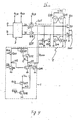
- the memory device according to the present embodiment is obtained by replacing the output circuit 16 of the memory of Fig. 1 with the output circuit 16' of Fig. 4. Therefore, in the following, explanation is given to the output circuit 16'.
- the output circuit 16' includes a pre-driver circuit 3 which is enabled by ⁇ CA and reset by ⁇ CR , a latch circuit 2 for holding data at a pair of signal lines OUT and OUT , a pair of N-channel transfer gate transistors Q 17 and Q 18 coupled between OUT, OUT and outputs D1 and D1 of the circuit 3, a push-pull output circuit composed of N-channel transistors Q 11 and Q 12 , and a latch control circuit 1.
- the latch control circuit 1 is composed of N-channel transistors Q 21 to Q 28 and have the signals ⁇ CA , CA S , and ⁇ RAS .
- the ⁇ RAS is the signal of the same phase as RAS and may be RAS itself or PR1 in Fig. 1.
- the control circuit 1 generates an output-off signal ⁇ OFF of level "1" when RAS and CAS are both at their inactive (high, "1") levels, and generates ⁇ OFF of level "0" when both of RAS and CAS are active (low level) and when one of RAS and CAS is maintained active after the active states of both RAS and CAS .
- the output terminal Dour is connected to the transistors Q 1 . and Q 12 , and the signal lines OUT and OUT are connected to the gates of the transistors Q 11 and Q 12 .
- the signal lines OUT and OUT are both of the level "0"
- the transistors Q 11 and O 12 are rendered nonconductive, and therefore the output terminal Dour assumes a high-impedance condition.
- either one of the output lines OUT and OUT assumes the level "1 ", either one of the transistors Q 11 and Q 12 is rendered conductive correspondingly to produce the output "1" " or "0" at Dour.
- the circuit 3 is inactivated or reset by the signal ⁇ CR , activated by an activating signal ⁇ CA , and produces outputs D 1 and D 1 in response to data at the bus lines D and D from the memory cell.
- the signal ⁇ CA has the level "1”
- the outputs D 1 , D 1 are transmitted to the signal lines OUT and OUT through the transistors Q 17 and Q 18 , so that either one of the output transistors Q 11 and Q 12 is rendered conductive with the other nonconductive.
- N-channel transistors Q 13 and Q 14 constitute a flip-flop for latching the signals of signal lines OUT and OUT , and work to stabilize the level "0" at the output D ouT .
- N-channel transistors Q 15 and Q 16 work as switches so that the signal lines OUT and OUT both are clamped to the level "0" whtn the output-off signal ⁇ OFF is of "1" level.
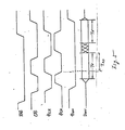
- Fig. 5 is a diagram of signal waveforms for explaining the operation of the embodiment.
- the signals RAS and CAS are under the activated condition when they have the level "0" according to the customary manner.
- the signal RAS is activated and then the signel CAS is activated
- the signal ⁇ CR changes from “1” to “0”
- the signal ⁇ OFF changes from “1” to “0”.
- the signal ⁇ CA changes from "0” to "1”
- the outputs D 1 and D 1 of the circuit 3 are transmitted to the signal lines OUT and to determine the output signal Dour.
- the signal ⁇ CR assumes the level "0"
- the signal ⁇ CA assumes the level "1”
- the data of the previous cycle is destroyed as the signal lines OUT and OUT are connected to the output terminals D 1 and D 1 of the circuit 3. Since the signal ⁇ CA assumes the level "1”, the data appears after a predetermined access time has passed. Thereafter, as the signal RAS is inactivated, the enable signals all change into the inactivated state. Therefore, the signal ⁇ CA changes into the level "0” and the reset signal ⁇ CR changes into the level "1” separately from the control of the signal C AS However, since the output-off signal ⁇ OFF maintains the level "0", the output continues to maintain the same data at Dour.
- the output Dour assumes a high-impedance condition.
- the internal enable signals generated from GAS are all inactivated when the RAS is inactivated irrespective of whether the CAS is activated or inactivated. This is to decrease the consumption of electric power since there is no need of carrying out the input or output operation when there is no access to the memory cell. Therefore, as the signal RAS is inactivated, the signal ⁇ CA assumes the level "0", and the signal ⁇ RAS assumes the level "1 ".
- the transistors Q 25 and 0 27 are rendered nonconductive and the signal CAS assumes the condition "1" (i.e., inactivated condition)
- the transistor Q 26 is rendered conductive and the transistor Q 28 is rendered conductive, so that nodes N2 and N3 assume the level "0".
- a node N1 i.e., the output-off signal ⁇ OFF assumes the level "1" due to the load circuit consisting of transistors Q 21 , Q 22 and a boot capacity C.
- the signal ⁇ CA maintains the level "0” even when the signal CAS of the level "0" is input from the external unit.
- the node N2 therefore is not allowed to assume the level "1”
- the output-off signal ⁇ OFF maintains the level "1” so that the output terminal Dour is maintained under a high-impedance condition.
- the CAS from the external unit assumes the level "0" as a matter of course, the signal ⁇ RAS assumes the level "0", the signal ⁇ CA assumes the level “1”, the nodes N2 and N3 both assumes the level “1”, and the output-off signal ⁇ OFF assumes the level "0".
- the signal CAS becomes inactive again, the node N2 assumes the level "0".
- the node N3 maintains the level "1” and the output-off signal ⁇ OFF maintains the level "0".
- the node N2 maintains the level "1 no matter when the signal RAS is inactivated and the node N3 assumes the level "0".
- the output-off signal maintains the level “0” until the signal CA S of the level "1 " is input from the external unit, and the output-off signal ⁇ OFF of a predetermined waveform is obtained as shown in Fig. 2.
- the output-off signal ⁇ OFF of the level "1" is produced when the signals RAS and CAS are both under the inactivated condition, and the latch circuit 2 is disenabled.
- the output-off signal 0 OFF of the level "0" is produced to enable the latch circuit 2 and the output data is latched therein.
- the output data continues to be latched even when both of these signals assume different conditions, because the output-off signal ⁇ OFF is in the "0" level at that time. Therefore, effective time of output can be extended, and high-speed operation can be carried out, while maintaining compatibility with the existing random access memory.
Landscapes
- Dram (AREA)
- Static Random-Access Memory (AREA)
Applications Claiming Priority (2)
| Application Number | Priority Date | Filing Date | Title |
|---|---|---|---|
| JP150353/86 | 1986-06-25 | ||
| JP61150353A JPS637591A (ja) | 1986-06-25 | 1986-06-25 | アドレスマルチプレクス型半導体メモリ |
Publications (2)
| Publication Number | Publication Date |
|---|---|
| EP0254065A2 true EP0254065A2 (de) | 1988-01-27 |
| EP0254065A3 EP0254065A3 (de) | 1990-07-04 |
Family
ID=15495134
Family Applications (1)
| Application Number | Title | Priority Date | Filing Date |
|---|---|---|---|
| EP87109120A Withdrawn EP0254065A3 (de) | 1986-06-25 | 1987-06-25 | Halbleiterspeicher vom Adressenmultiplex-Typ |
Country Status (2)
| Country | Link |
|---|---|
| EP (1) | EP0254065A3 (de) |
| JP (1) | JPS637591A (de) |
Cited By (2)
| Publication number | Priority date | Publication date | Assignee | Title |
|---|---|---|---|---|
| DE19539682A1 (de) * | 1994-11-30 | 1996-06-05 | Mitsubishi Electric Corp | Halbleiterspeicher mit erweiterter Datenausgabefunktion |
| EP0755539A4 (de) * | 1994-04-11 | 1997-11-12 | Intel Corp | Verbessertes preis-/leistungs-speichereinheitssystem mit einem dynamischen ram-speicher mit ausgebreitetem datenausgang |
Families Citing this family (2)
| Publication number | Priority date | Publication date | Assignee | Title |
|---|---|---|---|---|
| JPH02198095A (ja) * | 1989-01-26 | 1990-08-06 | Hitachi Ltd | ダイナミックramおよびその制御方法 |
| JPH0438793A (ja) * | 1990-06-04 | 1992-02-07 | Toshiba Corp | データ転送制御回路およびこれを用いたダイナミック型半導体記憶装置 |
Family Cites Families (5)
| Publication number | Priority date | Publication date | Assignee | Title |
|---|---|---|---|---|
| JPS5625290A (en) * | 1979-08-07 | 1981-03-11 | Nec Corp | Semiconductor circuit |
| JPS59207091A (ja) * | 1983-05-10 | 1984-11-24 | Toshiba Corp | ダイナミツクメモリのデ−タ出力回路 |
| EP0125699A3 (de) * | 1983-05-17 | 1986-10-08 | Kabushiki Kaisha Toshiba | Datenausgabeanordnung für einen dynamischen Speicher |
| US4567579A (en) * | 1983-07-08 | 1986-01-28 | Texas Instruments Incorporated | Dynamic memory with high speed nibble mode |
| JPS60117492A (ja) * | 1983-11-29 | 1985-06-24 | Fujitsu Ltd | 半導体記憶装置 |
-
1986
- 1986-06-25 JP JP61150353A patent/JPS637591A/ja active Pending
-
1987
- 1987-06-25 EP EP87109120A patent/EP0254065A3/de not_active Withdrawn
Cited By (3)
| Publication number | Priority date | Publication date | Assignee | Title |
|---|---|---|---|---|
| EP0755539A4 (de) * | 1994-04-11 | 1997-11-12 | Intel Corp | Verbessertes preis-/leistungs-speichereinheitssystem mit einem dynamischen ram-speicher mit ausgebreitetem datenausgang |
| DE19539682A1 (de) * | 1994-11-30 | 1996-06-05 | Mitsubishi Electric Corp | Halbleiterspeicher mit erweiterter Datenausgabefunktion |
| DE19539682C2 (de) * | 1994-11-30 | 2000-05-18 | Mitsubishi Electric Corp | Halbleiterspeicher mit erweiterter Datenausgabefunktion |
Also Published As
| Publication number | Publication date |
|---|---|
| EP0254065A3 (de) | 1990-07-04 |
| JPS637591A (ja) | 1988-01-13 |
Similar Documents
| Publication | Publication Date | Title |
|---|---|---|
| US4685089A (en) | High speed, low-power nibble mode circuitry for dynamic memory | |
| US4567579A (en) | Dynamic memory with high speed nibble mode | |
| US4586167A (en) | Semiconductor memory device | |
| US4429375A (en) | Consecutive addressing of a semiconductor memory | |
| EP0214180B1 (de) | Integrierter RAM-Speicher | |
| KR940000148B1 (ko) | 듀얼포트 반도체 기억장치 | |
| US4344156A (en) | High speed data transfer for a semiconductor memory | |
| KR100247873B1 (ko) | 반도체 기억 장치와 데이터 독출 및 기록 방법 | |
| EP0143647B1 (de) | Halbleiterspeicheranordnung | |
| US4222112A (en) | Dynamic RAM organization for reducing peak current | |
| US4817057A (en) | Semiconductor memory device having improved precharge scheme | |
| EP0056240B1 (de) | Speicheranordnung | |
| EP0128499A2 (de) | MOS-Speicher | |
| US4754433A (en) | Dynamic ram having multiplexed twin I/O line pairs | |
| EP0145488A2 (de) | Halbleiterspeicheranordnung | |
| US5088062A (en) | Memory device having common data lines for reading and writing | |
| US4281401A (en) | Semiconductor read/write memory array having high speed serial shift register access | |
| US4831590A (en) | Semiconductor memory including an output latch having hysteresis characteristics | |
| US4797573A (en) | Output circuit with improved timing control circuit | |
| US4354259A (en) | Semiconductor memory device having improved column selection structure | |
| KR880013070A (ko) | 디지탈 신호처리장치 | |
| EP0254065A2 (de) | Halbleiterspeicher vom Adressenmultiplex-Typ | |
| US4875189A (en) | Random access memory device with nibble mode operation | |
| US5561639A (en) | Semiconductor memory device with high speed detect function | |
| EP0162234A2 (de) | Speicheranordnung |
Legal Events
| Date | Code | Title | Description |
|---|---|---|---|
| PUAI | Public reference made under article 153(3) epc to a published international application that has entered the european phase |
Free format text: ORIGINAL CODE: 0009012 |
|
| 17P | Request for examination filed |
Effective date: 19870625 |
|
| AK | Designated contracting states |
Kind code of ref document: A2 Designated state(s): DE FR GB |
|
| PUAL | Search report despatched |
Free format text: ORIGINAL CODE: 0009013 |
|
| AK | Designated contracting states |
Kind code of ref document: A3 Designated state(s): DE FR GB |
|
| 17Q | First examination report despatched |
Effective date: 19911024 |
|
| STAA | Information on the status of an ep patent application or granted ep patent |
Free format text: STATUS: THE APPLICATION HAS BEEN WITHDRAWN |
|
| 18W | Application withdrawn |
Withdrawal date: 19920103 |
|
| RIN1 | Information on inventor provided before grant (corrected) |
Inventor name: WATANABE, HIROSHI |