EP0254281A2 - Machine pour le traitement de plumes de volaille ou similaire - Google Patents
Machine pour le traitement de plumes de volaille ou similaire Download PDFInfo
- Publication number
- EP0254281A2 EP0254281A2 EP87110569A EP87110569A EP0254281A2 EP 0254281 A2 EP0254281 A2 EP 0254281A2 EP 87110569 A EP87110569 A EP 87110569A EP 87110569 A EP87110569 A EP 87110569A EP 0254281 A2 EP0254281 A2 EP 0254281A2
- Authority
- EP
- European Patent Office
- Prior art keywords
- drum
- tube
- machine according
- air
- machine
- Prior art date
- Legal status (The legal status is an assumption and is not a legal conclusion. Google has not performed a legal analysis and makes no representation as to the accuracy of the status listed.)
- Granted
Links
- 210000003746 feather Anatomy 0.000 title claims abstract description 14
- 244000144977 poultry Species 0.000 title claims abstract description 13
- 238000001816 cooling Methods 0.000 claims abstract description 17
- 238000010438 heat treatment Methods 0.000 claims description 7
- 239000000645 desinfectant Substances 0.000 claims description 2
- 238000007873 sieving Methods 0.000 claims 1
- 238000001035 drying Methods 0.000 abstract description 8
- 238000005406 washing Methods 0.000 description 4
- 238000004140 cleaning Methods 0.000 description 2
- 230000000249 desinfective effect Effects 0.000 description 2
- 238000010410 dusting Methods 0.000 description 2
- 238000007689 inspection Methods 0.000 description 2
- 238000000034 method Methods 0.000 description 2
- 238000011144 upstream manufacturing Methods 0.000 description 2
- 239000004480 active ingredient Substances 0.000 description 1
- 239000013543 active substance Substances 0.000 description 1
- 238000010276 construction Methods 0.000 description 1
- 230000002349 favourable effect Effects 0.000 description 1
- 238000002156 mixing Methods 0.000 description 1
- 238000012216 screening Methods 0.000 description 1
- 230000035945 sensitivity Effects 0.000 description 1
- 238000005507 spraying Methods 0.000 description 1
Images
Classifications
-
- B—PERFORMING OPERATIONS; TRANSPORTING
- B68—SADDLERY; UPHOLSTERY
- B68G—METHODS, EQUIPMENT, OR MACHINES FOR USE IN UPHOLSTERING; UPHOLSTERY NOT OTHERWISE PROVIDED FOR
- B68G3/00—Treating materials to adapt them specially as upholstery filling
- B68G3/08—Preparation of bed feathers from natural feathers
- B68G3/10—Cleaning or conditioning of bed feathers
Definitions
- the invention relates to a machine of the type specified in the preamble of claim 1.
- Such a machine serves to cool the already dried, still hot springs, which are sucked in by means of a blower and blown into the drum through one of the tubes serving as the hollow axis. After switching on the suction side, cooling air is pressed into the drum using the same fan. The cooling air escapes through a screening device which is arranged in the same end wall of the drum into which the cooling air inlet also opens. The cooled springs are sucked off via the other tube serving as the hollow axis with the aid of a further fan. Disadvantages are the unfavorable cooling air flow, which requires a long cooling time, and the fact that the poultry springs are conveyed through a fan both for loading and unloading and are therefore partially damaged.
- a machine for drying poultry feathers is known from EP 0 181 270 A1, which consists of a drum rotating in an airtight housing with a drum casing designed as a sieve, through which hot air flows from bottom to top.
- the continuous drum shaft is hollow and serves as a line for spraying the springs with certain active ingredients. This makes loading and unloading the drum difficult, since at least one of the drum end walls must be provided with an additional opening serving this purpose.
- the air flow is not particularly favorable with this machine either.
- Treatment of poultry feathers or the like includes washing, disinfecting, drying, cooling and dusting the feathers.
- a special washing machine is used for washing.
- the subsequent treatment steps currently require three different devices or machines, namely a machine for disinfecting and drying the washed feathers, an upstream silo, since the capacity of the drying machine is only about a third of the washing machine capacity, and a machine for cooling and dusting. These three units naturally take up a lot of space.
- the invention has for its object to reduce this space requirement and for this purpose to design a machine of the type specified in the introduction such that it not only permits the treatment of a substantially larger amount of spring by an improved air guidance (and thus makes an upstream silo unnecessary) but also the gentle one All of the aforementioned treatment processes can be carried out.
- the above object is achieved in that the drum is surrounded by an airtight housing which is connected to the suction side of a blower and has a closable air inlet opening, that the drum jacket is designed as a sieve, and that one of the pipes is connected to a heating register for generating warm air via a switching element.
- This design achieves a very high drying capacity and an equally high cooling capacity, since the warm air or (after switching) the cold air reaches and flushes practically all parts of the inside of the drum, because the air flow spreads radially from the drum axis.
- a further improvement of the air flow is achieved by the training according to claim 2.
- the feature of claim 3 improves the mixing of the poultry feathers and thus shortens the treatment time.
- the claims 4, 5, 8 and 9 relate to structurally preferred embodiments of the air duct outside the drum or the housing.
- the embodiment according to claim 10 describes a drum drive which makes it possible to make the drum relatively light in spite of its generally considerable size, without this being necessary the resulting twist sensitivity is noticeably noticeable.
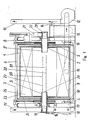
- the drum 1 is rotatably mounted on bushes 2 on fixed tubes 3 and 3 'serving as the hollow axis.
- the tubes 3, 3 ⁇ rest on trestles 4.
- the drum 1 can be driven by an electric motor 8 which is arranged on the trestle 4 on the right in FIG. 1 and drives a common drive shaft 7, which is also mounted on the trestles 4, and which drives in turn, two belt pulleys 5 are set in rotation via drive belts, which are connected in a rotationally fixed manner to the bushes 2 and consequently also to the drum 1.
- This drive construction avoids torsion and asymmetrical loads on the drum, which usually has a considerable diameter (for example up to 4 meters).
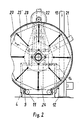
- the drum 1 is located in an essentially airtight housing 6, which is pivotable about a certain angle about the axis formed by the tubes 3 and 3 ⁇ .
- the housing 6 is mounted on the bushes 2 via bearing bushes between the drum end walls and the belt pulleys 5.
- the housing 6 has a housing base 9 which can be lowered via the working cylinder 10.
- the working cylinders 10 are supported against the trestles 4. When the housing 6 is pivoted, its base 9 thus remains stationary.
- connection 11 opens out, which is connected via a tube to the suction side of a blower 12, on the pressure side of which an exhaust air tube 13 is connected to a branch 14 for circulating air.
- the circulating air flows through a filter 15 and a circulating air pipe 16 to a heating register 17 which is equipped with an adjustable flap 18 for the admixture of fresh air.
- the pipes 3 and. 3 ⁇ are completed at their outer ends by rotary valves 19 and 29.
- the tube 3 can be connected either to the heating register 17 or to a cooling air tube 22.
- the tube 3 ⁇ can optionally be connected to a loading tube 20 or an unloading tube 21.
- Both tubes 3 and 3 ⁇ are connected to the inside of the drum 1 via end openings 26.
- two pipes 30, 31, only indicated schematically, are led through the pipe 3 into the interior of the drum 1 and end in nozzles 27 and 28, respectively.
- the jacket of the drum 1 is formed by jacket screens 23.
- the end walls of the drum 1 are predominantly formed by end wall screens 24.
- the machine works as follows: The electric motor 8 and the blower 12 are switched on and the rotary slide valve 29 establishes the connection between the loading tube 23 and the drum 1 via pipe 3 ⁇ in order to suck in the wet poultry springs. After loading, the rotary valve 29 is closed and the rotary valve 19 now connects the drum 1 to the heating register 17, so that warm air is sucked in through the pipe 3 and sucked out through the blower 12. In the meantime, a disinfectant can be sprayed in via the nozzles 28 and further active substances can be sprayed in via the nozzles 29. After the springs have dried, the rotary valve 19 is switched over and now connects the drum 1 to the cooling air tube 22 for cooling the springs.
- the rotary valve 19 For unloading, the rotary valve 19 is closed, the rotary valve 29 is brought into the position connecting the tube 3 'with the unloading tube 21 and the fan 12 is switched off.
- the poultry feathers can now be sucked out of the inside of the drum 1 by means of a bagging system.
- the housing base 9 is lowered by the working cylinder 10. The air then flows through the sieves in the opposite direction and frees them from adhering poultry feathers.
- the housing base 9 When the housing base 9 is lowered, the housing 6 can be pivoted into any angular position.
- the large opening in the housing that is freed up in this way allows convenient inspection, possibly also cleaning or replacement of the screens.
Landscapes
- Engineering & Computer Science (AREA)
- Mechanical Engineering (AREA)
- Housing For Livestock And Birds (AREA)
- Meat, Egg Or Seafood Products (AREA)
- Drying Of Solid Materials (AREA)
- Chemical Or Physical Treatment Of Fibers (AREA)
Priority Applications (1)
| Application Number | Priority Date | Filing Date | Title |
|---|---|---|---|
| AT87110569T ATE64728T1 (de) | 1986-07-21 | 1987-07-21 | Maschine zum behandeln von gefluegelfedern oder dergleichen. |
Applications Claiming Priority (2)
| Application Number | Priority Date | Filing Date | Title |
|---|---|---|---|
| DE3624613 | 1986-07-21 | ||
| DE19863624613 DE3624613A1 (de) | 1986-07-21 | 1986-07-21 | Maschine zum behandeln von gefluegelfedern oder dergl. |
Publications (3)
| Publication Number | Publication Date |
|---|---|
| EP0254281A2 true EP0254281A2 (fr) | 1988-01-27 |
| EP0254281A3 EP0254281A3 (en) | 1988-10-19 |
| EP0254281B1 EP0254281B1 (fr) | 1991-06-26 |
Family
ID=6305634
Family Applications (1)
| Application Number | Title | Priority Date | Filing Date |
|---|---|---|---|
| EP19870110569 Expired - Lifetime EP0254281B1 (fr) | 1986-07-21 | 1987-07-21 | Machine pour le traitement de plumes de volaille ou similaire |
Country Status (3)
| Country | Link |
|---|---|
| EP (1) | EP0254281B1 (fr) |
| AT (1) | ATE64728T1 (fr) |
| DE (2) | DE3624613A1 (fr) |
Cited By (5)
| Publication number | Priority date | Publication date | Assignee | Title |
|---|---|---|---|---|
| GR890100119A (el) * | 1989-02-24 | 1991-06-28 | Denaxas Georgios E E | Μηχάνημα καθαρισμού γουνών και απορροφήσεως υπολειμμάτων με ρελέαναστροφής κάδου και χρονοδιακόπτη. |
| FR2702642A1 (fr) * | 1993-03-18 | 1994-09-23 | Mimouni Hubert | Procédé d'obtention d'une nappe à rembourrage de laine soufflée, nappe ainsi obtenue, et sac de couchage constitué de telles nappes. |
| CN101328656B (zh) * | 2008-07-19 | 2011-08-31 | 徐州腾宇羽绒设备有限公司 | 羽绒洗脱机 |
| CN109140587A (zh) * | 2018-08-20 | 2019-01-04 | 刘真林 | 空气消毒净化器 |
| CN113145557A (zh) * | 2021-04-07 | 2021-07-23 | 六安市富成羽毛制品有限公司 | 一种羽毛球生产用洗毛设备 |
Family Cites Families (2)
| Publication number | Priority date | Publication date | Assignee | Title |
|---|---|---|---|---|
| DE570358C (de) * | 1934-12-11 | 1933-02-15 | Akt Ges Maschf | Maschine zum Reinigen, Waschen, Daempfen und Trocknen von Bettfedern |
| DE3502496C1 (de) * | 1985-01-25 | 1986-04-10 | Heinz Ing.(grad.) 8600 Bamberg Herbertz | Wasch- und Schleudermaschine fuer Bettfedern und aehnliches Waschgut |
-
1986
- 1986-07-21 DE DE19863624613 patent/DE3624613A1/de not_active Withdrawn
-
1987
- 1987-07-21 EP EP19870110569 patent/EP0254281B1/fr not_active Expired - Lifetime
- 1987-07-21 AT AT87110569T patent/ATE64728T1/de not_active IP Right Cessation
- 1987-07-21 DE DE8787110569T patent/DE3771011D1/de not_active Expired - Lifetime
Cited By (6)
| Publication number | Priority date | Publication date | Assignee | Title |
|---|---|---|---|---|
| GR890100119A (el) * | 1989-02-24 | 1991-06-28 | Denaxas Georgios E E | Μηχάνημα καθαρισμού γουνών και απορροφήσεως υπολειμμάτων με ρελέαναστροφής κάδου και χρονοδιακόπτη. |
| FR2702642A1 (fr) * | 1993-03-18 | 1994-09-23 | Mimouni Hubert | Procédé d'obtention d'une nappe à rembourrage de laine soufflée, nappe ainsi obtenue, et sac de couchage constitué de telles nappes. |
| CN101328656B (zh) * | 2008-07-19 | 2011-08-31 | 徐州腾宇羽绒设备有限公司 | 羽绒洗脱机 |
| CN109140587A (zh) * | 2018-08-20 | 2019-01-04 | 刘真林 | 空气消毒净化器 |
| CN113145557A (zh) * | 2021-04-07 | 2021-07-23 | 六安市富成羽毛制品有限公司 | 一种羽毛球生产用洗毛设备 |
| CN113145557B (zh) * | 2021-04-07 | 2024-02-02 | 六安市富成羽毛制品有限公司 | 一种羽毛球生产用洗毛设备 |
Also Published As
| Publication number | Publication date |
|---|---|
| DE3624613A1 (de) | 1988-01-28 |
| ATE64728T1 (de) | 1991-07-15 |
| EP0254281A3 (en) | 1988-10-19 |
| DE3771011D1 (de) | 1991-08-01 |
| EP0254281B1 (fr) | 1991-06-26 |
Similar Documents
| Publication | Publication Date | Title |
|---|---|---|
| DE2918762C2 (de) | Vorrichtung zum Überziehen bzw. Kandieren von körnigem Gut | |
| DE60304948T2 (de) | Wäschetrommeltrockner mit Abluft | |
| CH625720A5 (fr) | ||
| EP0217263B1 (fr) | Machine pour le traitement par la chaleur | |
| EP0254281B1 (fr) | Machine pour le traitement de plumes de volaille ou similaire | |
| DE60211410T2 (de) | Maschine zur Reinigung einer Plane | |
| DE19623959B4 (de) | Verfahren zum Betreiben eines Wäschetrockners und Wäschetrockner mit einer drehbar gelagerten Wäschetrommel | |
| DE69616503T2 (de) | Vorrichtung zur Trockenbehandlung eines Gewebes | |
| DE1460709B2 (de) | Siebtrommeltrockner | |
| DE68902294T2 (de) | Vorrichtung zur beschichlung von pulverigen oder koernigen stoffen. | |
| DE69417256T2 (de) | Trocknungsvorrichtung für eine beschichtungsmaschine | |
| EP0166190A2 (fr) | Dispositif de nettoyage pour un échangeur de chaleur de régénération | |
| DE4321869C2 (de) | Vorrichtung zum Entfernen von sich auf Textilmaschinen absetzendem Flug | |
| DE2513660A1 (de) | Trommelmaschine zum behandeln von stueckgut | |
| EP0744212A2 (fr) | Tambour pour enrober | |
| DE69120451T2 (de) | Umfüllvorrichtung für Material in Turmmälzereien | |
| DE10064548A1 (de) | Wasch- und Trocknermaschine | |
| DE4244038C1 (de) | Vorrichtung zum streifen- oder tropfenförmigen Ausbringen fließfähiger Massen | |
| DE3516207A1 (de) | Vorrichtung zum behandeln von tabak | |
| DE373722C (de) | Baumwoll-Transportanlage | |
| DE10202375C2 (de) | Verfahren und Vorrichtung zum Trocknen von Fahrzeugen | |
| DE3607850A1 (de) | Vorrichtung zum desinfizieren, trocknen, kuehlen und entstauben von gefluegelfedern oder dergl. | |
| DE9208292U1 (de) | Trocknungsvorrichtung | |
| EP0853691B1 (fr) | Ouvreuse de matieres fibreuses en flocons | |
| DE423573C (de) | Vorrichtung zum Kuehlen von geschmolzenen Fettmassen oder Emulsionen |
Legal Events
| Date | Code | Title | Description |
|---|---|---|---|
| PUAI | Public reference made under article 153(3) epc to a published international application that has entered the european phase |
Free format text: ORIGINAL CODE: 0009012 |
|
| AK | Designated contracting states |
Kind code of ref document: A2 Designated state(s): AT BE CH DE FR GB IT LI LU NL SE |
|
| PUAL | Search report despatched |
Free format text: ORIGINAL CODE: 0009013 |
|
| AK | Designated contracting states |
Kind code of ref document: A3 Designated state(s): AT BE CH DE FR GB IT LI LU NL SE |
|
| 17P | Request for examination filed |
Effective date: 19881007 |
|
| 17Q | First examination report despatched |
Effective date: 19901030 |
|
| GRAA | (expected) grant |
Free format text: ORIGINAL CODE: 0009210 |
|
| AK | Designated contracting states |
Kind code of ref document: B1 Designated state(s): AT BE CH DE FR GB IT LI LU NL SE |
|
| PG25 | Lapsed in a contracting state [announced via postgrant information from national office to epo] |
Ref country code: SE Effective date: 19910626 Ref country code: NL Effective date: 19910626 Ref country code: FR Effective date: 19910626 Ref country code: BE Effective date: 19910626 |
|
| REF | Corresponds to: |
Ref document number: 64728 Country of ref document: AT Date of ref document: 19910715 Kind code of ref document: T |
|
| PG25 | Lapsed in a contracting state [announced via postgrant information from national office to epo] |
Ref country code: AT Effective date: 19910721 |
|
| PG25 | Lapsed in a contracting state [announced via postgrant information from national office to epo] |
Ref country code: LU Free format text: LAPSE BECAUSE OF NON-PAYMENT OF DUE FEES Effective date: 19910731 Ref country code: LI Effective date: 19910731 Ref country code: CH Effective date: 19910731 |
|
| REF | Corresponds to: |
Ref document number: 3771011 Country of ref document: DE Date of ref document: 19910801 |
|
| ITF | It: translation for a ep patent filed | ||
| EN | Fr: translation not filed | ||
| RAP2 | Party data changed (patent owner data changed or rights of a patent transferred) |
Owner name: L.H. LORCH AG MASCHINENFABRIK |
|
| RIN2 | Information on inventor provided after grant (corrected) |
Free format text: HERBERTZ, HEINZ |
|
| ITPR | It: changes in ownership of a european patent |
Owner name: CESSIONE;L.H. LORCH AKTIENGESELLSCHAFT |
|
| NLV1 | Nl: lapsed or annulled due to failure to fulfill the requirements of art. 29p and 29m of the patents act | ||
| BECN | Be: change of holder's name |
Effective date: 19910626 |
|
| GBV | Gb: ep patent (uk) treated as always having been void in accordance with gb section 77(7)/1977 [no translation filed] | ||
| REG | Reference to a national code |
Ref country code: GB Ref legal event code: 777A |
|
| REG | Reference to a national code |
Ref country code: CH Ref legal event code: PL |
|
| PLBE | No opposition filed within time limit |
Free format text: ORIGINAL CODE: 0009261 |
|
| STAA | Information on the status of an ep patent application or granted ep patent |
Free format text: STATUS: NO OPPOSITION FILED WITHIN TIME LIMIT |
|
| GBT | Gb: translation of ep patent filed (gb section 77(6)(a)/1977) | ||
| REG | Reference to a national code |
Ref country code: GB Ref legal event code: 777B Ref country code: GB Ref legal event code: 732 |
|
| 26N | No opposition filed | ||
| PGFP | Annual fee paid to national office [announced via postgrant information from national office to epo] |
Ref country code: GB Payment date: 19920713 Year of fee payment: 6 |
|
| PGFP | Annual fee paid to national office [announced via postgrant information from national office to epo] |
Ref country code: DE Payment date: 19920930 Year of fee payment: 6 |
|
| PG25 | Lapsed in a contracting state [announced via postgrant information from national office to epo] |
Ref country code: GB Effective date: 19930721 |
|
| GBPC | Gb: european patent ceased through non-payment of renewal fee |
Effective date: 19930721 |
|
| PG25 | Lapsed in a contracting state [announced via postgrant information from national office to epo] |
Ref country code: DE Effective date: 19940401 |
|
| PG25 | Lapsed in a contracting state [announced via postgrant information from national office to epo] |
Ref country code: IT Free format text: LAPSE BECAUSE OF NON-PAYMENT OF DUE FEES;WARNING: LAPSES OF ITALIAN PATENTS WITH EFFECTIVE DATE BEFORE 2007 MAY HAVE OCCURRED AT ANY TIME BEFORE 2007. THE CORRECT EFFECTIVE DATE MAY BE DIFFERENT FROM THE ONE RECORDED. Effective date: 20050721 |