EP0254285A2 - Speicherung von Information mit hoher Dichte auf einer Speicherplatte - Google Patents
Speicherung von Information mit hoher Dichte auf einer Speicherplatte Download PDFInfo
- Publication number
- EP0254285A2 EP0254285A2 EP87110594A EP87110594A EP0254285A2 EP 0254285 A2 EP0254285 A2 EP 0254285A2 EP 87110594 A EP87110594 A EP 87110594A EP 87110594 A EP87110594 A EP 87110594A EP 0254285 A2 EP0254285 A2 EP 0254285A2
- Authority
- EP
- European Patent Office
- Prior art keywords
- disc
- pit
- information
- pits
- reference signal
- Prior art date
- Legal status (The legal status is an assumption and is not a legal conclusion. Google has not performed a legal analysis and makes no representation as to the accuracy of the status listed.)
- Withdrawn
Links
Images

Classifications
-
- G—PHYSICS
- G11—INFORMATION STORAGE
- G11B—INFORMATION STORAGE BASED ON RELATIVE MOVEMENT BETWEEN RECORD CARRIER AND TRANSDUCER
- G11B20/00—Signal processing not specific to the method of recording or reproducing; Circuits therefor
- G11B20/10—Digital recording or reproducing
- G11B20/10009—Improvement or modification of read or write signals
- G11B20/10037—A/D conversion, D/A conversion, sampling, slicing and digital quantisation or adjusting parameters thereof
-
- G—PHYSICS
- G11—INFORMATION STORAGE
- G11B—INFORMATION STORAGE BASED ON RELATIVE MOVEMENT BETWEEN RECORD CARRIER AND TRANSDUCER
- G11B19/00—Driving, starting, stopping record carriers not specifically of filamentary or web form, or of supports therefor; Control thereof; Control of operating function ; Driving both disc and head
- G11B19/02—Control of operating function, e.g. switching from recording to reproducing
-
- G—PHYSICS
- G11—INFORMATION STORAGE
- G11B—INFORMATION STORAGE BASED ON RELATIVE MOVEMENT BETWEEN RECORD CARRIER AND TRANSDUCER
- G11B20/00—Signal processing not specific to the method of recording or reproducing; Circuits therefor
- G11B20/10—Digital recording or reproducing
- G11B20/10009—Improvement or modification of read or write signals
-
- G—PHYSICS
- G11—INFORMATION STORAGE
- G11B—INFORMATION STORAGE BASED ON RELATIVE MOVEMENT BETWEEN RECORD CARRIER AND TRANSDUCER
- G11B20/00—Signal processing not specific to the method of recording or reproducing; Circuits therefor
- G11B20/10—Digital recording or reproducing
- G11B20/10009—Improvement or modification of read or write signals
- G11B20/10222—Improvement or modification of read or write signals clock-related aspects, e.g. phase or frequency adjustment or bit synchronisation
-
- G—PHYSICS
- G11—INFORMATION STORAGE
- G11B—INFORMATION STORAGE BASED ON RELATIVE MOVEMENT BETWEEN RECORD CARRIER AND TRANSDUCER
- G11B7/00—Recording or reproducing by optical means, e.g. recording using a thermal beam of optical radiation by modifying optical properties or the physical structure, reproducing using an optical beam at lower power by sensing optical properties; Record carriers therefor
- G11B7/004—Recording, reproducing or erasing methods; Read, write or erase circuits therefor
-
- G—PHYSICS
- G11—INFORMATION STORAGE
- G11B—INFORMATION STORAGE BASED ON RELATIVE MOVEMENT BETWEEN RECORD CARRIER AND TRANSDUCER
- G11B7/00—Recording or reproducing by optical means, e.g. recording using a thermal beam of optical radiation by modifying optical properties or the physical structure, reproducing using an optical beam at lower power by sensing optical properties; Record carriers therefor
- G11B7/007—Arrangement of the information on the record carrier, e.g. form of tracks, actual track shape, e.g. wobbled, or cross-section, e.g. v-shaped; Sequential information structures, e.g. sectoring or header formats within a track
- G11B7/00745—Sectoring or header formats within a track
-
- G—PHYSICS
- G11—INFORMATION STORAGE
- G11B—INFORMATION STORAGE BASED ON RELATIVE MOVEMENT BETWEEN RECORD CARRIER AND TRANSDUCER
- G11B7/00—Recording or reproducing by optical means, e.g. recording using a thermal beam of optical radiation by modifying optical properties or the physical structure, reproducing using an optical beam at lower power by sensing optical properties; Record carriers therefor
- G11B7/08—Disposition or mounting of heads or light sources relatively to record carriers
- G11B7/09—Disposition or mounting of heads or light sources relatively to record carriers with provision for moving the light beam or focus plane for the purpose of maintaining alignment of the light beam relative to the record carrier during transducing operation, e.g. to compensate for surface irregularities of the latter or for track following
- G11B7/0938—Disposition or mounting of heads or light sources relatively to record carriers with provision for moving the light beam or focus plane for the purpose of maintaining alignment of the light beam relative to the record carrier during transducing operation, e.g. to compensate for surface irregularities of the latter or for track following servo format, e.g. guide tracks, pilot signals
-
- H—ELECTRICITY
- H04—ELECTRIC COMMUNICATION TECHNIQUE
- H04N—PICTORIAL COMMUNICATION, e.g. TELEVISION
- H04N5/00—Details of television systems
- H04N5/76—Television signal recording
- H04N5/84—Television signal recording using optical recording
- H04N5/85—Television signal recording using optical recording on discs or drums
-
- H—ELECTRICITY
- H04—ELECTRIC COMMUNICATION TECHNIQUE
- H04N—PICTORIAL COMMUNICATION, e.g. TELEVISION
- H04N5/00—Details of television systems
- H04N5/76—Television signal recording
- H04N5/91—Television signal processing therefor
- H04N5/92—Transformation of the television signal for recording, e.g. modulation, frequency changing; Inverse transformation for playback
Definitions
- the invention relates to optical data and information storage systems, especially systems using lasers for encoding and reading.
- the invention relates to a system for encoding and reading samples of analog information on an optical disc, in a manner that achieves high density and high precision.
- One important feature of the invention is the ability to achieve optical information storage at sufficient density that a video picture can be stored and generated in one revolution of a compact optical disc, with a 2 ⁇ inner diameter for recording.
- a second feature is the ability to sample at a bandwidth greater than 10 MHz to obtain a high resolution video picture.
- Optical data storage systems involve encoding of information by burning pits or exposing photoresist into the surface of a data storage medium, which may be a rotatable disc.
- the pits can either burn through the medium or create holes in a developed photoresist, creating a light transmissive opening which is read from the other side of the medium, or simply make a reflective medium surface nonreflective at the location of the pit, in systems which read reflected light.
- the pits usually generated by a laser beam, can carry information either by digital storage encoding or analog encoding. In digital encoding, at each reading location there is either a pit or no pit. In analog systems, information can be represented by the length of a pit, or the distance between pits, or both.
- analog information was contained in the length of each pit, and also repeated by the length between pits, FM modulation.
- the object was to reduce noise, by making a double encoding and a double reading of each sample, then averaging the two in the reading mode in order to reproduce the information more precisely.
- Such systems have been effective in reducing noise, they have been inefficient in the sense that additional space is required for the double recording of each bit of information on the disc.
- video discs for example, this has led to the need for a 12 ⁇ disc, with accurate encoding only possible beginning at about 4 ⁇ of diameter and extending outwardly.
- one revolution of the disc is used to generate a video picture, or frame, in the CAV mode (constant angular velocity), and with the prior encoding systems there was not sufficient storage space available in a revolution inside the 4 ⁇ diameter line.
- U.S. Patent No. 4,175,270 issued to George Zenzefilis discloses an information storage system which utilizes a series of magnetic reference signals encoded on the magnetic medium and dividing up the storage medium, and which involves encoding of information in such a way as to straddle a magnetic reference signal located on the inner portion of the disc. (See, e.g., Figure 5A).
- This is in the context of magnetic storage, not optical storage.
- the magnetic storage domain for each bit of information takes up considerably more medium space than does optical storage, presenting different considerations.
- the patent discloses a photographically-encoded embodiment, but not one using laser encoding and reading, especially of reflective surfaces.
- Zenzefilis encodes his "clock track" of reference signals at an inner location on a video disc, near the center, and his system requires two pickup heads, one in fixed radial position for detecting the clock track signals, and one positioned outwardly and radially movable for picking up the video information. Still further, in Zenzefilis' system each segment or sample of information is associated with an element of the video display, i.e., a pixel containing chroma and luminance information, and all segments are arrayed in radial lines along the clock signals so that discrete segments from circumferential path to path corresponding to a particular element or pixel are located at generally the same angular position from the center of rotation.
- an element of the video display i.e., a pixel containing chroma and luminance information
- high density, low noise optical data storage is achieved by using a series of precisely timed electronic reference signals, dividing each revolution of an optical storage disc into a large number of spaces or references.
- Each pit written on the optical storage medium is synchronized to one of the electronic reference signals.
- the electronic reference signals are generated by a phase lock loop oscillator that is synchronized with reading of the disc, and this synchronization occurs during a time or portion of the disc wherein no information is being read. For the video signals this time represents the vertical and horizontal retrace times.
- the electronic reference signal forms an end of each sample of analog information stored on the medium.
- this is accomplished by writing each pit across an electronic reference signal, such that the pit contains two samples of information: the length of the pit from its leading edge to the location of the reference signal represents one sample, while the length of the pit from the reference to the pit's trailing edge represents a different sample.
- a further feature of the invention is that a reference frequency is stored in pits on the disc, so that regardless of motor speed variation the samples around the circumferential paths will be correlated to prevailing motor speed.
- These reference pits are located in the vertical retrace interval on each path, or in both vertical retrace intervals with the conventional two fields per frame.
- each pit does not contain both chroma and luminance information, i.e., a pixel or picture element. Rather, both ends of a given pit contain either chroma and luminance, as part of a curve that carries chroma and luminance. This is in contrast to the prior art Zenzefilis system.
- a further feature of the invention is that the reference frequency of the electronic reference signal is stored in pits on the disc, so that regardless of motor speed variation the samples around the circumferential paths will be correlated to the prevailing motor speed, at least at the start of a revolution.
- these frequency reference pits are located in the vertical retrace interval on each track, or in both vertical retrace intervals with the conventional two fields per frame. In other data storage applications they can be located in any selected interval.
- the electronic reference signal in accordance with preferred embodiments of the invention is generated by a crystal controlled sync generator in the recording mode, and by a phase lock loop in the reading mode.
- the phase lock loop in association with the demodulator, picks up the frequency of the frequency reference pits, and adjusts to that frequency and sets oscillation at that frequency, until another series of frequency reference pits are encountered, in the next field.
- each pit does not contain both chroma and luminance information, i.e., a pixel or picture element. Rather, both ends of a given pit contain either chroma and luminance, as part of a curve that carries chroma and luminance. This is in contrast to the prior art Zenzefilis system.
- the synchronous signal for each horizontal line is encoded just before the chroma and luminance information.
- the FM signal must be decoded to obtain the sync signal. If the FM signal is weak it may not be decoded and the sync signal will be lost.
- the sync signal is stripped from the video signal, and encoded as a simple digital signal ta the end of the horizontal retrace time.
- the sync signal is easily read without demodulation being necessary.
- the chroma and luminance signals are demodulated and added to a regenerated sync signal to obtain a standard NTSC video signal.
- a further objective is the mixing of video information, digital information, and digital audio information on the same disc.
- the discs will normally spin at 1800 RPM in CAV mode and at 800 RPM to 1800 RPM in constant linear velocity mode.
- Figure 1 shows a WRITE or RECORD system 10 in accordance with the principles of the invention, in block diagram form.
- an optical disc 12 is driven by a motor 14 while being encoded by a write head 16, preferably a laser write head.
- the motor is connected to a motor controller 18 which receives a signal from a crystal controlled sync generator 20.
- a video signal is being encoded on the optical disc 12.
- a video tape player 22 may be the source of the video signal, and it is connected to a video signal processor 24 and to the sync generator 20, there being synchronizing reference signals on the tape being encoded.
- Reference numbers are associated with each frame to permit random interactive access to each frame.
- Each frame can be video, digital or audio data. The intial samples of information identify each track and direct the electronic signals to the appropriate decoding electronics.
- a modulator 26 modulates the fisnal from the signal processor 24 to a form which enables the write head 16 to encode the video signal data in the form of pits on the disc 12 in accordance with the invention.
- the sync generator 20 is also connected to the modulator 26 to control the timing of the modulation and encoding of data onto the disc.
- FIG 2 shows a READ subsystem 30 of the invention, for decoding the information encoded on the disc 12 and for feeding the information to a video monitor 32.
- a laser read head 34 picks up information from pits encoded on the disc 12, the disc being driven by a motor 36.
- the motor speed is controlled by a phase lock loop including a motor controller 38 fed a signal by a crystal oscillator 40, with feedback to the controller 38 from the read head 34.
- the read head picks up sync signals from the disc 12 and these are fed back to the motor controller 38 to as nearly as possible keep the disc 12 rotating at the prescribed speed.
- a demodulator 42 of the system accordingly includes a phase lock loop for setting an oscillation in accordance with sensed prevailing motor speed, thereby creating an electronic reference signal which can be precisely timed to the pits encoded in accordance with this invention, as further explained below.
- the phase locked loop may be altered by changing its characteristics from a low "Q" or resonance momentum for setting the frequency to a higher "Q” or resonance momentum for maintaining a constant frequency during a horizontal line time sequence.
- the referenced equipment and circuitry is known to those skilled in the art and does not form a specific part of this invention.
- Figure 3 shows the disc 12 and the location of the pits 41 for setting the reference signal frequency. These are located in the area or time of the vertical retrace interval.
- the pits are uniform and at a frequency of 5.35 MHz for high density encoding or at a frequency of 10.7 MHz for high resolution encoding.
- the information pits 43 contain the double samples of information.
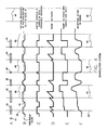
- Figure 4 shows the demodulation system as associated with individual pits and the electronically generated reference signals.
- An electronic ramp voltage is started at the beginning of each pit and at the electronic reference signal 48.
- the sample and hold is turned on at the time of the reference signal and at the end of each pit.
- the final regenerator wave form may contain the synchronous signal, the chroma signal and the luminance, or the synchronous signal may be transferred digitally since it is a single pulse and only the chroma and luminance transferred in analog manner.
- a video wave form is shown but other wave forms may be used that require transfer and timing.
- the system of this invention may be used for other types of data storage, although this preferred embodiment is illustrated and described in connection with video.
Landscapes
- Engineering & Computer Science (AREA)
- Signal Processing (AREA)
- Multimedia (AREA)
- Optical Recording Or Reproduction (AREA)
- Signal Processing For Digital Recording And Reproducing (AREA)
- Signal Processing Not Specific To The Method Of Recording And Reproducing (AREA)
Applications Claiming Priority (2)
| Application Number | Priority Date | Filing Date | Title |
|---|---|---|---|
| US890705 | 1986-07-25 | ||
| US06/890,705 US4736258A (en) | 1986-07-25 | 1986-07-25 | High density storage of information on a compact disc |
Publications (2)
| Publication Number | Publication Date |
|---|---|
| EP0254285A2 true EP0254285A2 (de) | 1988-01-27 |
| EP0254285A3 EP0254285A3 (en) | 1989-07-12 |
Family
ID=25397037
Family Applications (1)
| Application Number | Title | Priority Date | Filing Date |
|---|---|---|---|
| EP87110594A Withdrawn EP0254285A3 (en) | 1986-07-25 | 1987-07-22 | High density storage of information on a compact disc |
Country Status (4)
| Country | Link |
|---|---|
| US (1) | US4736258A (de) |
| EP (1) | EP0254285A3 (de) |
| JP (1) | JPS6379278A (de) |
| CA (1) | CA1296424C (de) |
Families Citing this family (10)
| Publication number | Priority date | Publication date | Assignee | Title |
|---|---|---|---|---|
| NL8701632A (nl) * | 1987-07-10 | 1989-02-01 | Philips Nv | Systeem voor het optekenen en/of uitlezen van een informatiesignaal, een registratiedrager, een opteken en/of uitleesinrichting voor toepassing in een dergelijk systeem, en een inrichting en werkwijze voor het vervaardigen van een dergelijke registratiedrager. |
| US5321672A (en) * | 1989-04-19 | 1994-06-14 | Hitachi, Ltd. | Method of an apparatus for magneto-optically recording information by changing the position or shape or controlling the diameter of reversed domains |
| JP3173839B2 (ja) * | 1992-01-17 | 2001-06-04 | パイオニア株式会社 | 記録媒体用情報再生装置及び再生方法 |
| US5652824A (en) * | 1993-10-29 | 1997-07-29 | Tokyo Shibaura Electric Co | Multilingual recording medium and reproducing apparatus with automatic selection of substitutes and languages based on frequency of selections |
| EP0836192A1 (de) * | 1993-10-29 | 1998-04-15 | Kabushiki Kaisha Toshiba | Aufzeichnungsmedium für Mehrfachszenen, und Verfahren und Vorrichtung zur Wiedergabe von Daten davon |
| US5764846A (en) * | 1993-10-29 | 1998-06-09 | Kabushiki Kaisha Toshiba | Multi-scene recording medium and apparatus for reproducing data therefrom |
| US5850500A (en) * | 1995-06-28 | 1998-12-15 | Kabushiki Kaisha Toshiba | Recording medium comprising a plurality of different languages which are selectable independently of each other |
| US5721720A (en) * | 1994-12-28 | 1998-02-24 | Kabushiki Kaisha Toshiba | Optical recording medium recording pixel data as a compressed unit data block |
| US6009202A (en) * | 1994-12-28 | 1999-12-28 | Kabushiki Kaisha Toshiba | Image information encoding/decoding system |
| US5784519A (en) * | 1995-06-15 | 1998-07-21 | Kabushiki Kaisha Toshiba | Multi-scene recording medium and apparatus for reproducing data therefrom |
Family Cites Families (4)
| Publication number | Priority date | Publication date | Assignee | Title |
|---|---|---|---|---|
| US4175270A (en) * | 1970-03-27 | 1979-11-20 | Zenzefilis George E | Method and apparatus for recording and reproducing video |
| US4161752A (en) * | 1977-06-28 | 1979-07-17 | International Business Machines Corporation | High density video disk having two pit depths |
| JPS57198546A (en) * | 1981-05-29 | 1982-12-06 | Fuji Xerox Co Ltd | Optical information recording and reproducing method |
| US4428075A (en) * | 1981-12-21 | 1984-01-24 | Burroughs Corporation | Methods of preformatting an optical disk |
-
1986
- 1986-07-25 US US06/890,705 patent/US4736258A/en not_active Expired - Fee Related
-
1987
- 1987-07-22 EP EP87110594A patent/EP0254285A3/en not_active Withdrawn
- 1987-07-24 JP JP62183767A patent/JPS6379278A/ja active Pending
- 1987-07-24 CA CA000542981A patent/CA1296424C/en not_active Expired - Lifetime
Also Published As
| Publication number | Publication date |
|---|---|
| JPS6379278A (ja) | 1988-04-09 |
| EP0254285A3 (en) | 1989-07-12 |
| CA1296424C (en) | 1992-02-25 |
| US4736258A (en) | 1988-04-05 |
Similar Documents
| Publication | Publication Date | Title |
|---|---|---|
| US5297131A (en) | Eccentricity detection and compensation of a disk by a preformatted encoding pattern | |
| US5148422A (en) | Optical recording medium having a data recording track with offset data storing regions | |
| US5459710A (en) | Apparatus for recording information in data sections having number of bytes which increases with increase in circumference of tracks on medium | |
| KR100378646B1 (ko) | 광학식기록매체,및이것으로부터신호를기록하고재생하는방법 | |
| US5448545A (en) | System for reproducing digital information in a pulse-length modulation format | |
| US5233589A (en) | Method for recording/reproducing information having a function of correcting variations in the interval in reproduced data and apparatus for realizing same | |
| US4688205A (en) | Data demodulation apparatus | |
| US20070291615A1 (en) | Optical disc and physical address format | |
| JPS60106073A (ja) | 記録再生装置 | |
| JPH01224929A (ja) | 光学的に読み出し可能な書込可能型記録担体及びそのような記録担体を製造する方法及びそのような記録担体を用いて情報の記録/再生を行う装置 | |
| JPH01220126A (ja) | 情報信号を記録する方法及び装置 | |
| US4736258A (en) | High density storage of information on a compact disc | |
| EP1519379A1 (de) | Optisches aufzeichnungsmedium, informationsverarbeitungseinrichtung mit dem aufzeichnungsmedium und datenaufzeichnungsverfahren | |
| JPS634476A (ja) | 情報記録装置 | |
| EP0397354A2 (de) | Gerät zur Ermittlung des Übersprechniveaus eines optischen Lesesignales | |
| EP0425475B1 (de) | System zur Übertragung und Erkennung von Daten | |
| US5592457A (en) | System for recording digital information in a pulse-length modulation format | |
| US4205339A (en) | Frame storage and retrieval wherein the frame fields are quadrature amplitude modulated on a single carrier | |
| US4491877A (en) | Cross-talk detector in information-carrying disc player | |
| JPS604631B2 (ja) | 回転記録媒体に対するテレビジヨン信号の記録方式 | |
| JPH06290465A (ja) | 光ディスク記録媒体 | |
| JPS59144289A (ja) | 静止画像信号再生装置 | |
| JP2615564B2 (ja) | データ記録方法 | |
| NL8003482A (nl) | Werkwijze en inrichting voor het coderen en decoderen van gegevenssignalen, die op een informatiedrager zijn geregistreerd. | |
| JP3089497B2 (ja) | 記録再生装置及び再生装置 |
Legal Events
| Date | Code | Title | Description |
|---|---|---|---|
| PUAI | Public reference made under article 153(3) epc to a published international application that has entered the european phase |
Free format text: ORIGINAL CODE: 0009012 |
|
| AK | Designated contracting states |
Kind code of ref document: A2 Designated state(s): DE FR GB NL |
|
| PUAL | Search report despatched |
Free format text: ORIGINAL CODE: 0009013 |
|
| AK | Designated contracting states |
Kind code of ref document: A3 Designated state(s): DE FR GB NL |
|
| 17P | Request for examination filed |
Effective date: 19900108 |
|
| 17Q | First examination report despatched |
Effective date: 19920421 |
|
| STAA | Information on the status of an ep patent application or granted ep patent |
Free format text: STATUS: THE APPLICATION IS DEEMED TO BE WITHDRAWN |
|
| 18D | Application deemed to be withdrawn |
Effective date: 19960201 |