EP0254458B1 - Apparat und Verfahren zum Umwickeln von Rollen von druckempfindlichem Material - Google Patents
Apparat und Verfahren zum Umwickeln von Rollen von druckempfindlichem Material Download PDFInfo
- Publication number
- EP0254458B1 EP0254458B1 EP87306112A EP87306112A EP0254458B1 EP 0254458 B1 EP0254458 B1 EP 0254458B1 EP 87306112 A EP87306112 A EP 87306112A EP 87306112 A EP87306112 A EP 87306112A EP 0254458 B1 EP0254458 B1 EP 0254458B1
- Authority
- EP
- European Patent Office
- Prior art keywords
- rolls
- wrapping
- shafts
- winder
- wrapped
- Prior art date
- Legal status (The legal status is an assumption and is not a legal conclusion. Google has not performed a legal analysis and makes no representation as to the accuracy of the status listed.)
- Expired - Lifetime
Links
- 239000000463 material Substances 0.000 title claims abstract description 51
- 238000000034 method Methods 0.000 title claims description 9
- 239000006261 foam material Substances 0.000 claims abstract description 39
- 238000004804 winding Methods 0.000 claims abstract description 20
- 239000006260 foam Substances 0.000 claims description 14
- 239000000853 adhesive Substances 0.000 claims 1
- 230000001070 adhesive effect Effects 0.000 claims 1
- 239000003292 glue Substances 0.000 description 18
- 238000010276 construction Methods 0.000 description 11
- 125000006850 spacer group Chemical group 0.000 description 7
- 230000008878 coupling Effects 0.000 description 6
- 238000010168 coupling process Methods 0.000 description 6
- 238000005859 coupling reaction Methods 0.000 description 6
- 239000000123 paper Substances 0.000 description 4
- 230000009977 dual effect Effects 0.000 description 3
- 230000007246 mechanism Effects 0.000 description 3
- 241000282472 Canis lupus familiaris Species 0.000 description 2
- 229910000760 Hardened steel Inorganic materials 0.000 description 1
- 239000004698 Polyethylene Substances 0.000 description 1
- 229910000831 Steel Inorganic materials 0.000 description 1
- 230000000712 assembly Effects 0.000 description 1
- 238000000429 assembly Methods 0.000 description 1
- 238000006073 displacement reaction Methods 0.000 description 1
- 238000012986 modification Methods 0.000 description 1
- 230000004048 modification Effects 0.000 description 1
- NJPPVKZQTLUDBO-UHFFFAOYSA-N novaluron Chemical compound C1=C(Cl)C(OC(F)(F)C(OC(F)(F)F)F)=CC=C1NC(=O)NC(=O)C1=C(F)C=CC=C1F NJPPVKZQTLUDBO-UHFFFAOYSA-N 0.000 description 1
- 238000004806 packaging method and process Methods 0.000 description 1
- 210000000006 pectoral fin Anatomy 0.000 description 1
- 239000004033 plastic Substances 0.000 description 1
- 229920003023 plastic Polymers 0.000 description 1
- -1 polyethylene Polymers 0.000 description 1
- 229920000573 polyethylene Polymers 0.000 description 1
- 239000010959 steel Substances 0.000 description 1
- 239000002699 waste material Substances 0.000 description 1
Images



Classifications
-
- B—PERFORMING OPERATIONS; TRANSPORTING
- B65—CONVEYING; PACKING; STORING; HANDLING THIN OR FILAMENTARY MATERIAL
- B65B—MACHINES, APPARATUS OR DEVICES FOR, OR METHODS OF, PACKAGING ARTICLES OR MATERIALS; UNPACKING
- B65B11/00—Wrapping, e.g. partially or wholly enclosing, articles or quantities of material, in strips, sheets or blanks, of flexible material
- B65B11/04—Wrapping, e.g. partially or wholly enclosing, articles or quantities of material, in strips, sheets or blanks, of flexible material the articles being rotated
Definitions
- This invention relates to apparatus and a method for wrapping rolls of pressure sensitive sheet material, for example, carbonless copying paper has to be carefully wrapped so that any external pressures do not cause marking of the paper and the present invention is particularly applicable to rolls of such pressure sensitive material. It is known to wrap material of this kind with a foam material, for example polyethylene packaging foam and the present invention is intended to provide apparatus and a method for wrapping rolls of pressure sensitive sheet material in a limited amount of space and with a minimum amount of manual handling.
- European Patent Application EP-A 0 054 903 discloses apparatus for wrapping a roll of pressure sensitive material with, for example, a paper wrapper.
- the roll is first wound on a hollow core and its dimensions are monitored.
- the inner core is used by a lifting device provided with clamping heads which engage on this hollow core.
- the lifting device places the roll in position for wrapping at a winding station.
- This earlier construction merely shows a means for winding a single roll of material at a time, the follow core of the roll being used to move and rotate it.
- apparatus for winding and wrapping rolls of pressure sensitive sheet material includes means (26) for winding two or more rolls (20) of pressure sensitive material on the same or separate removable winder shafts (24), transfer means (19),(28),(30) for moving the wound rolls to a rapping location where they are wrapped with sheet foam, and wrapping means (34) including slitter means (76) for slitting a sheet of foam material (21) into separate widths appropriate to the width of each roll (20) to be wrapped and for simultaneously wrapping said widths of foam material onto each of said rolls (20) whilst they are rotated on their winder shaft or shafts (24).
- the transfer means act to move said rolls (20) from a winder unit (26) to the wrapping location by their winder shaft or shafts (24).
- the transfer means may include a movable support on which the rolls are wrapped and which is movable from a loading position in which the rolls are received to the wrapping position in which the rolls are wrapped by said wrapping means.
- the movable support includes means for rotating the roll thereon when in the wrapping location.
- the movable support may conveniently be in the form of a cart.
- the wrapping means is preferably movable from an inoperative position above the rolls when in the wrapping location of the transfer means to an operative wrapping position adjacent the rolls to be wrapped.
- the movable support means can be provided with means for raising the wrapped rolls to permit removal of their winder shaft or shafts and means can also be included for removing the winder shaft from the rolls after wrapping.
- Means may be included for winding separate rolls on two or more separate parallel winder shafts, the wrapping means being between the rolls when in the operative wrapping position.
- Means may be included on the movable support for supporting and rotating the rolls when in the wrapping position and for adjusting the distance between their winder shafts.
- the said separate rolls are located at the wrapping location with their axes substantially parallel but unaligned in their axial directions.
- each winder shaft can be arranged to carry two or more axially spaced apart rolls.
- the wrapping means can include means for cutting the foam wrapping material after a predetermined length has been supplied together with means for securing the tail end of the length of material in position on the wrapped roll.
- the invention also includes a method of wrapping rolls of pressure sensitive sheet material which includes winding two or more rolls (20) of pressure sensitive material on the same or separate winder shafts (24), transferring the wound rolls to a wrapping location, slitting a sheet of foam material (21) into separate widths appropriate to the width of each roll (20) to be wrapped and simultaneously wrapping said widths of foam material onto each of said rolls (20) whilst they are rotated on their winder shaft or shafts (24).
- Advantages of the apparatus over other proposed systems include a minimal amount of travel for naked (unwrapped) rolls of pressure sensitive material. Once the material has been foam wrapped it can be rolled and handled as a non-pressure sensitive roll of material. Moreover, operators of the machine will be in close proximity to all the functions as they occur. All the rolls on both winder shafts, if two or more are used, are wrapped simultaneously from one full width of sheet foam material and the apparatus has the ability to handle dual yardage demands. Due to the efficiency of this system, there is a minimal amount of foam material waste and a much smaller amount of space is required than in conventional systems.
- the apparatus comprises a winder unit 26 on which two winder core shafts 24 are positioned in bearings. Each winder core shaft 24 receives thereon a roll of pressure sensitive material indicated by reference numeral 20.
- Transfer means for moving the wound rolls includes a bi-directional hoist 28 which is provided with six hooks 19 arranged in two rows of three. The hooks 19 can engage the winder shafts 24, lift them and transfer them to a transfer cart 30.
- the bi-directional hoist 28 is arranged above the winder unit 26 and can move from that position, which is indicated by broken line 16, to the position shown in full lines in Figure 1, movement of the hoist 28 is indicated by arrow 18.
- the transfer cart 30 also forms part of the transfer means and acts as a movable support from a loading position indicated by broken lines 17 adjacent the winder unit 26 to a wrapping location where it is shown in full lines.
- a retractable wrapping unit 34 is located above the wrapping position and can move downwards to the position shown in full lines in Figure 1.
- Foam wrapping material 21 is supplied from a roll 15, over a plurality of guides 36 to the wrapping unit 34.
- a number (two are shown) of removal carts 32 are provided to receive foam material wrapped pressure sensitive rolls 22 which have been wrapped, to transfer them to a remote location.
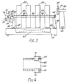
- the construction of the transfer cart 30 is shown more clearly in Figure 2, 3 and 4 and comprises a base platform 31 mounted on rollers or wheels 33.
- Two pairs of roll pedestals 38 are carried on lead screws 42 so that the distance between the pedestals and therefore between the roll centres of the rolls when carried on them can be adjusted.
- two scissor-lift tables 40 which can be raised from a lowered position on the base 31 to the raised positions indicated by broken lines 35.
- the roll pedestals 38 carry suitable bearings, not shown, to receive the winder shafts 24.
- each of the core shafts 24 is provided with keyways 37 and these are engaged by a clutch/drive coupling 62 which is connected to an air motor 56 carried on a sliding mounting 39.
- the mounting is located on one of the pair of roll supports 38 and an air cylinder 54 is provided to move the carriage 39 in the direction of the arrow 41 to cause the clutch/drive coupling 62 to engage the keyways 37 in the end of the winder shaft 24.
- the clutch/drive coupling 62 comprises a sleeve 66 provided with resiliently loaded pivotted dogs 68 which are held inwardly by a garter spring 70. The dogs engage in the keyways 37 when the clutch/drive coupling is moved into position by the air ram 54. Operation of the air motor 56 will now cause the winder shaft 24 to rotate.
- a winder shaft puller 46 In order to remove the rolls 20 when wrapped a winder shaft puller 46 is provided.
- the end of the winder shaft 24 remote from the end carrying the keyways 37 is provided with an enlarged portion 44.
- the core shaft puller 46 is movable in the direction of the arrows 43 and is provided with a recessed portion 52 which can receive the enlarged portion 44 of the drive shaft therein and securing mechanism 48 which fastens over the raised portion 44 by rotating about a hinge 50.
- the scissor lift table 40 When the winding operation has been finished the scissor lift table 40 is raised to the position shown in broken lines 35 in Figure 2 and so that the portion 44 of the winder shaft 24 is aligned with the recess 52 of the shaft puller.
- the shaft puller is now moved and locked in position and then withdrawn, taking the winder shaft 24 with it.
- the wound rolls are now left standing on the table 40 which can subsequently be lowered to allow them to be rolled off and onto the carts 32.
- the spacers 60 and cores 64 are arranged on each of the two winder shafts 24 so that the rolls on one shaft are unaligned with the rolls on the other.
- the rolls on the shaft which is not shown in Figure 3 will be spaced so that they align with the spacers 60 on the winder shaft 24 which is shown.
- the transfer cart when loaded and in the wrapping position has two rows of axially spaced apart rolls, one set of rolls being unaligned with the other but being aligned with the spaces between the other set of rolls.
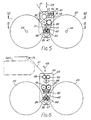
- the wrapping means 34 comprises end supports 43 between which are arranged various rollers and other mechanisms which extend across the full width of the set of rolls to be wrapped.
- the sheet of foam material 21 is received from the full width sheet roll and is fed through an idler roll 72 which presses it against a hardened anvil backing roll 74 which co-operates with a slitter 76.
- the slitter 76 acts to slit the full width of the foam material 21 into predetermined widths and is controlled by a computorised slitting system incorporated in the slitter construction and which is not shown in detail. This control system instructs the slitter cutters to provide the required widths corresponding to the widths of the pressure sensitive rolls 20.
- the foam material now passes between a rubber covered roll 78 which is geared to a knife ejector roll 82.
- the roll 82 is also controlled to cut the foam material into the required lengths to cover the rolls 20 and a selective glue system 80 applies glue to the tail end of the cut lengths.
- the apparatus 80 incorporates deflector means (described in more detail in Figures 9 and 10) which acts to deflect alternate widths of foam material in opposite directions and over a splitter or deflector 45 so that the widths of foam material are deflected alternately towards appropriate rolls on each of the two roll shafts 24.
- a pair of rider rolls 84 which are movable in the direction shown by arrows 47 act to apply a minimum nip pressure against the pressure sensitive rolls.
- core shafts are driven to provide the desired number of foam wraps and a trim pick-up hopper 86 is provided to catch any excess length of foam.
- the wrapper means 34 is retractable from a position above the rolls 20, the general direction of movement being indicated by arrows 49.
- Figure 6 shows an alternative construction of wrapper means in which the same reference numerals are used to indicate similar parts.
- the full width foam material 21 passes through dual rubber covered hold back rolls 90 and through a slitting system indicated by reference numeral 88.
- a rubber covered backing roll 78 and rubber covered knife ejector roll 83 act to determine the length of foam material being passed therethrough when a predetermined portion has been wrapped around pressure sensitive rolls 20.
- a selective glue system 80 applies glue to the tail end of the material at the completion of the wrapping procedure.
- Deflection means are again incorporated in the system 80 so that the widths of material diverted over the deflector 45 and once again a pair of rider rolls 84 provide a minimum amount of nip pressure against the pressure sensitive rolls 20.
- the rider rolls 84 when in position against the foam material and against the rolls 20 also aid in rotation of the rolls.
- a trim pick-up hopper 86 once again collects the scraps left from the foam material. It will be appreciated that the rider rolls 84 are driven.
- Figure 7 shows the pull roll/knife roll combination of the unit shown in Figure 5.
- Covered roll 78 and knife ejector roll 82 are located in position between a set of six rolls 20 which have been loaded onto core shafts 24.
- the core sleeves 64 and spacers 60 are also shown.
- the cores 64 can typically be of cardboard and be about 3 inches in diameter by 4.32 inches outer diameter and are approximately the width of the roll 20.
- the spacers 60 are typically again, about 3 inches in diameter by 4 inches outer diameter and of various lengths of steel or plastics material. It will be seen from this Figure that when a full width of web of foam material 21 is slit into predetermined widths every other roll is wound upon the opposite shaft.
- the pressure sensitive material has, of course, previously been wound upon the cardboard core 64 at the winder unit 26.
- Figure 8 shows the backing roll 74 and parts of the slitter unit 76.
- the hardened steel backing roll 74 is positioned adjacent the slitter 76 which has a plurality of slitter assemblies 76a which cut the foam into the desired predetermined widths.
- the slitter holder may be of the kind commercially available as a Tidland Corporation No. EK-30 Knife Holder with necessary modifications to adapt it to the present invention. If automatic slitter positioning is utilised, two Festo Corporation DGO Rodless Cylinders and a Temposonics Incorporated Linear Displacement Transducer can be utilised.
- Figure 9 shows the location of the rider rolls 84. These rolls are retractable towards each other as shown by arrows 46 in Figures 5 and 6 and they are positioned between the plurality of pressure sensitive rolls as shown in Figure 9.
- the rider rolls 84 are driven in order to assist in turning the rolls 20 on their shafts and they act to press the widths of foam material against the rolls 20 so that they are wrapped around the circumference thereof.
- FIG 10 is a diagrammatic view of the air dividers and glue nozzles incorporated in apparatus 80, and Figure 11 is a cross-section through this apparatus.
- the air diverters are indicated by reference numeral 92 in Figure 10 and selective glue nozzles are indicated by reference numeral 94.
- These devices are positioned parallel to the lengths of the core shafts 24 and are arranged so that when the divided widths of foam material are delivered from the knife ejector roll 83 they are selectively deflected by the air diverters towards an appropriate roll 20 with glue being applied to the tail end of each piece.
- the glue nozzles also act to apply glue to the front end of each width of material.
- reference numeral 96 indicates selective air headers for assisting in the selective application of glue to the widths of material, indicated by reference numeral 21 and it will be appreciated that the various glue applicators and air nozzles are arranged in groups on either side of the foam material 21 to divert appropriate widths of material.
- one diverted length of material is indicated by reference numeral 51 and the other by reference numeral 53.
- empty core shafts 24 are set up on the winder 26 with appropriate spacers 60 and cores 64 for the required number of rolls. These empty shafts are collected from the transfer cart 30 where they have been previously placed. They are placed in position by the hoist 28. The rolls of pressure sensitive material are rolled on the winder apparatus 26 and when completed the hoist 28 is moved over the winder to the position indicated by reference numeral 16 so that the completed rolls can be raised on their shafts 24. The hoist is moved to the position shown in full lines in Figure 1 and the shafts are deposited on the roll pedestals 38 on the transfer cart 30 which has been moved to the position indicated by broken line 17. If desired empty roll shafts 24 can be carried on the base of the cart 30 so that when full rolls 20 are loaded onto the cart the empty shafts 24 can be taken from the cart and placed in position on the winder 26 so that it can again immediately commence operation in winding further rolls.
- the roll widths and diameters (which are different if there is a dual yardage) are set up on the applicator unit and the transfer cart 30 is now moved approximately six feet from the loading position to the winding location beneath the winding means 34.
- the winding apparatus is set in motion and control apparatus operates to provide the following automatic actions.
- the apparatus is now operated, preferably by electrical control, so that a mere push button is possible, and this starts the foam wrapping material sequence so that the packng and knife ejector rolls, which are stepping motor controlled, are operated to metre the feed of the web of foam material into the wrapping unit.
- the control slitting system After the material has been slit into appropriate widths by the control slitting system it is moved downwardly so that the leading edge of each width is in line with the selective glue nozzles 92.
- the nozzles are arranged appropriately in groups to apply glue to the appropriate side of the widths of material and these nozzles now shoot glue onto whichever side of material is necessary to adhere to its respective roll of pressure sensitive material.
- the selective air nozzles 94 then operate and the foam material is then advanced until the glued leading edges are deflected and the widths of material more past the rider rolls 84.
- the rider rolls now move outwardly to apply a minimum amount of nip pressure against the rolls 20 and the foam drive rolls, core shafts and rider rolls are now operated so that the rolls 20 are rotated to provide the desired number of wrappings of foam material, after which the slitters disengage and reset to the next roll width and re-engage. It will be appreciated that this second roll width will have already been inserted into the control mechanism.
- the foam material has been advanced to where the "slit overlap" would be in the driving nip upon which the knife ejecter severs the foam.
- the selective glue nozzles then apply glue to the tail end of each width of foam material and the core shafts are again driven to pull the tail end from the nip and onto the finished rolls.
- the rider rolls 84 are now retracted and the roll pedestals 38 are returned to their original position by means of the lead screws 42.
- the foam material wrapping unit 34 now retracts to its position above the rolls.
- a second series of operations is now commenced, again electrically operated, which acts to move the wrapped rolls, indicated by reference numeral 22 in Figure 1, from the cart 30.
- the lift tables 40 are now actuated on the transfer cart 30 to lift each roll, and its winder shaft 24, from the roll pedestals 38 until they are aligned with the floor mounted core shaft puller 45.
- a single puller is shown but it will be appreciated that a double puller could be provided which will simultaneously engage both shafts.
- the pullers are locked into position and then moved in the direction of the arrows 43 to withdraw the winder shafts 24 from both the rolls.
- the spacers 60 will automatically disengage themselves as the shafts are withdrawn and will be collected for further use.
- the wrapped rolls 22 are now rolled onto the carts 32, the rolls being weaved as they are moved so that they are close together.
- the core shaft puller returns the empty winder shaft 24 to the roll pedestals and in order to assist this operation the roll pedestal 38 nearest to the winder 26 can be provided with an additional winder shaft support indicated by reference numeral 57 in Figure 2.
- the transfer cart 30 is now returned to its loading position indicated by reference numeral 17 ready to recommence operations.
- the apparatus of the present invention is unique in that it combines standard and non-standard equipment to handle a delicate application of foam material to rolls of pressure sensitive material.
- the movable support in the form of the transfer cart 30 in the arrangement described above can be used to move the rolls 20 to the area beneath the wrapping means and can be operated with existing hoists 28 which are usually provided with winder units 26.
Landscapes
- Engineering & Computer Science (AREA)
- Mechanical Engineering (AREA)
- Replacement Of Web Rolls (AREA)
- Basic Packing Technique (AREA)
- Treatment Of Fiber Materials (AREA)
- Laminated Bodies (AREA)
- Nitrogen And Oxygen Or Sulfur-Condensed Heterocyclic Ring Systems (AREA)
- Pharmaceuticals Containing Other Organic And Inorganic Compounds (AREA)
- Medicines Containing Plant Substances (AREA)
- Winding Of Webs (AREA)
- Rolls And Other Rotary Bodies (AREA)
Claims (17)
- Vorrichtung zum Aufwickeln und Verpacken von Rollen aus druckempfindlichem Material, beinhaltend Mittel (26) zum Aufwickeln von zwei oder mehr Rollen (20) aus druckempfindlichem Material auf die gleichen oder verschiedene entfernbare Wickelschäfte (24), Transportmittel (19), (28), (30) zum Transfer der gewickelten Rollen zu einer Verpackungsstelle, wo diese mit geschäumter Folie verpackt werden, und Verpackungsmittel (34), beinhaltend eine Rollenschneidemaschine (76) zum Schneiden eines Bogens aus Schaummaterial (21) in verschiedene Breiten, welche zu den Breiten jeder zu verpackenden Rolle (20) passen und zum gleichzeitigen Verpacken der genannten Rollen (20) mit den genannten Breiten aus Schaummaterial, während die Rollen sich auf ihrem Wickelschaft oder ihren Wickelschäften (24) drehen.
- Vorrichtung gemäß Anspruch 1, in welcher das genannte Transportmittel (19), (28), (30) wirkt, indem es die genannten Rollen (20) durch ihren Wickelschaft oder ihre Wickelschäfte (24) von einer Wickeleinheit (26) zu der Verpackungsstelle bringt.
- Vorrichtung gemäß Anspruch 2, in welcher das genannte Transportmittel (19) (28) (30) eine bewegliche Auflage (30) beinhaltet, auf welcher die Rollen (20) verpackt werden und welche beweglich ist von einer Ladestellung (17), in welcher die Rollen (20) empfangen werden zu genannter Verpackungsstelle, wo die Rollen (20) durch die genannten Verpackungsmittel (34) verpackt werden.
- Vorrichtung gemäß Anspruch 3, bei welcher die genannte bewegliche Auflage (30) Mittel zur Drehung der Rollen darauf beinhaltet, wenn sie in der genannten Verpackungsstellung ist.
- Vorrichtung gemäß Anspruch 4, bei der die genannte bewegliche Auflage (30) Mittel (56) (62) beinhaltet zur Rotation des Wickelschafts oder der Wickelschäfte (24), auf welchen sich die Rollen (20) befinden.
- Vorrichtung gemäß eines der Ansprüche 3 bis 5, bei welcher die genannte bewegliche Auflage als Karren (30) ausgebildet ist.
- Vorrichtung gemäß eines der Ansprüche 1 bis 6, bei der das genannte Verpackungsmittel (34) beweglich ist von einer Ruheposition über den Rollen (20), wenn das Transportmittel (19) (28) (30) am Verpackungsort ist, zu einer Arbeitsstellung anliegend an die zu verpackenden Rollen (20).
- Vorrichtung gemäß eines der Ansprüche 2 bis 7, bei welcher die bewegliche Auflage (30) mit Mitteln (40) zum Anheben der verpackten Rollen (20) versehen ist, um die Entfernung ihres Wickelschafts der ihrer Wickelschäfte (24) zu ermöglichen.
- Vorrichtung gemäß Anspruch 8, beinhaltend Mittel zur Entfernung des Wickelschafts oder der Wickelschäfte (24) von den Rollen (20) nach dem Verpackungsvorgang.
- Vorrichtung gemäß eines der Ansprüche 3 bis 9, bei der das Transportmittel (19) (28) (30) Hebezeuge (19) zur Bewegung der Rollen (20) von dem Wickelmittel (26) zu der beweglichen Auflage (30) beinhaltet.
- Vorrichtung gemäß eines der voranstehenden Ansprüche, welche Mittel zur Aufwicklung verschiedener Rollen (20) auf zwei oder mehr separate parallele Wickelschäfte (24) beinhaltet, wobei das genannte Verpackungsmittel (34) in seiner Arbeitsstellung zwischen den Rollen (20) ist.
- Vorrichtung gemäß Anspruch 11, bei welcher die bewegliche Auflage (30) Mittel (38) (42) (56) (62) beinhaltet zum Tragen und Rotieren der Rollen (20), wenn sie in ihrer Verpackungsstellung ist, und zum Einstellen der Entfernung zwischen den Wickelschäften (24).
- Vorrichtung gemäß eines der Ansprüche 11 oder 12, bei der die genannten separaten Rollen (20) am Verpackungsort mit im wesentlichen parallelen Achsen, aber in ihrer axialen Richtung unausgerichtet, plaziert sind.
- Vorrichtung gemäß eines der Ansprüche 11 oder 12, bei der jeder Wickelschaft (24) zwei oder mehr axial voneinander getrennte Rollen (20) trägt.
- Vorrichtung gemäß eines der voranstehenden Ansprüche, bei der das genannte Wickelmittel (34) Mittel (82) beinhaltet zum Schneiden des genannten geschäumten Verpackungsmaterials (21), nachdem eine vorbestimmte Länge abgewickelt wurde und Mittel (92) zur Sicherung des hinteren Endes der Länge des Materials auf den verpackten Rollen.
- Verfahren zum Aufwickeln und Verpacken von Rollen aus druckempfindlichem Material, beinhaltend die Aufwicklung von zwei oder mehreren Rollen (20) aus druckempfindlichem Material auf diesselben oder verschiedene Wickelschäfte (24), Transport der gewickelten Rollen zu einer Verpackungsstelle, Schneiden eines Bogens aus geschäumtem Material (21) in getrennte Breiten, welche zu der Breite jeder zu verpackenden Rolle (20) passen und gleichzeitiges Einwickeln jeder der genannten Rollen (20) mit genannten Breiten des geschäumten Materials, während diese Rollen auf ihrem Wickelschaft oder ihren Wickelschäften (24) gedreht werden.
- Verfahren gemäß Anspruch 16, welches folgende Schritte beinhaltet:(a) Anbringen des geschäumten Materials (21) an die Rollen (20) und Drehung der Rollen um eine vorbestimmte Anzahl an Umdrehungen, um eine vorbestimmte Anzahl von Schichten des geschäumten Materials (21) aufzubringen,(b) Zerteilen der genannten Breiten des geschäumten Materials (21) nachdem eine vorbestimmte Länge auf die Rolle (20) aufgewickelt wurde,(c) Anbringung eines Klebebandes an das hintere Ende der vorbestimmten Länge des Materials, um es festzukleben und damit den Verpackungsvorgang zu beenden.
Priority Applications (1)
| Application Number | Priority Date | Filing Date | Title |
|---|---|---|---|
| AT87306112T ATE68146T1 (de) | 1986-07-17 | 1987-07-10 | Apparat und verfahren zum umwickeln von rollen von druckempfindlichem material. |
Applications Claiming Priority (2)
| Application Number | Priority Date | Filing Date | Title |
|---|---|---|---|
| US06/886,432 US4707968A (en) | 1986-07-17 | 1986-07-17 | Method and apparatus for wrapping pressure sensitive rolls of material |
| US886432 | 1986-07-17 |
Publications (3)
| Publication Number | Publication Date |
|---|---|
| EP0254458A2 EP0254458A2 (de) | 1988-01-27 |
| EP0254458A3 EP0254458A3 (en) | 1989-02-01 |
| EP0254458B1 true EP0254458B1 (de) | 1991-10-09 |
Family
ID=25389041
Family Applications (1)
| Application Number | Title | Priority Date | Filing Date |
|---|---|---|---|
| EP87306112A Expired - Lifetime EP0254458B1 (de) | 1986-07-17 | 1987-07-10 | Apparat und Verfahren zum Umwickeln von Rollen von druckempfindlichem Material |
Country Status (9)
| Country | Link |
|---|---|
| US (1) | US4707968A (de) |
| EP (1) | EP0254458B1 (de) |
| JP (1) | JPS6333210A (de) |
| AT (1) | ATE68146T1 (de) |
| AU (1) | AU594794B2 (de) |
| CA (1) | CA1284944C (de) |
| DE (1) | DE3773569D1 (de) |
| FI (1) | FI81315C (de) |
| ZA (1) | ZA874927B (de) |
Families Citing this family (5)
| Publication number | Priority date | Publication date | Assignee | Title |
|---|---|---|---|---|
| JPS59204532A (ja) * | 1983-05-09 | 1984-11-19 | 王子製袋株式会社 | 袋の製造方法 |
| US4884385A (en) * | 1987-03-04 | 1989-12-05 | Appleton Papers Inc. | Interleaved spiral wrapping of foam product and stretch film for packaging carbonless paper rolls |
| SE9001334D0 (sv) * | 1990-04-12 | 1990-04-12 | Ulf Lindstrand | Kabeltrumma |
| US6895732B2 (en) * | 2002-09-09 | 2005-05-24 | Sealed Air Corporation (Us) | Packaging apparatus and method |
| US8490252B2 (en) | 2006-02-03 | 2013-07-23 | Stover Equipment Co., Inc. | Technique for removing a cover from cylindrical modules |
Citations (1)
| Publication number | Priority date | Publication date | Assignee | Title |
|---|---|---|---|---|
| GB932151A (en) * | 1961-05-15 | 1963-07-24 | Du Pont | Method and apparatus for winding a continuous web |
Family Cites Families (10)
| Publication number | Priority date | Publication date | Assignee | Title |
|---|---|---|---|---|
| US3521424A (en) * | 1967-05-02 | 1970-07-21 | Mobay Chemical Corp | Method of packaging foam articles |
| US3718302A (en) * | 1971-01-29 | 1973-02-27 | Midland Ross Corp | Coil and mandrel separating machinery |
| US4055313A (en) * | 1973-09-04 | 1977-10-25 | Nishimura Seisakusho Co., Ltd. | Apparatus for exchanging rewound rolls in a roll slitting and rewinding machine |
| US3924375A (en) * | 1974-05-23 | 1975-12-09 | Beloit Corp | Automatic crimper |
| DE2649431A1 (de) * | 1976-10-29 | 1978-05-03 | Saint Gobain | Mit einer aeusseren umhuellung versehene hohlzylinderfoermige spule oder packung aus aufgewickeltem fadenmaterial, insbesondere glasfaeden, mit innenabzug |
| JPS53115308A (en) * | 1977-03-04 | 1978-10-07 | Tokyo Kikai Seisakushiyo Kk | Device for automatically supplying rolled paper in rotary press |
| EP0044627B1 (de) * | 1980-06-25 | 1986-04-09 | Encomech Product Development Limited | Vorrichtung zum Verpacken einer Rolle von Folien- oder Bandmetall |
| FI811789L (fi) * | 1980-07-18 | 1982-01-19 | Jagenberg Werke Ag | Anordning foer separat upplindning av laengsgaoende banor |
| DE3049096C2 (de) * | 1980-12-24 | 1986-05-28 | Kleinewefers Gmbh, 4150 Krefeld | Verpackungseinrichtung für Rollen mit Innenhülse |
| DE3314289C2 (de) * | 1983-04-20 | 1987-01-02 | Grünzweig + Hartmann und Glasfaser AG, 6700 Ludwigshafen | Verfahren zum Umwickeln eines sich drehenden Ballens aus Wickelmaterial, insbesondere aus einer kaschierten Mineralfaserbahn, mit einer Schutzbahn zur Verpackung, sowie Vorrichtung zur Durchführung des Verfahrens |
-
1986
- 1986-07-17 US US06/886,432 patent/US4707968A/en not_active Expired - Lifetime
-
1987
- 1987-06-02 CA CA000538587A patent/CA1284944C/en not_active Expired - Lifetime
- 1987-07-03 FI FI872961A patent/FI81315C/fi not_active IP Right Cessation
- 1987-07-06 AU AU75261/87A patent/AU594794B2/en not_active Expired - Fee Related
- 1987-07-07 ZA ZA874927A patent/ZA874927B/xx unknown
- 1987-07-10 EP EP87306112A patent/EP0254458B1/de not_active Expired - Lifetime
- 1987-07-10 AT AT87306112T patent/ATE68146T1/de not_active IP Right Cessation
- 1987-07-10 DE DE8787306112T patent/DE3773569D1/de not_active Expired - Lifetime
- 1987-07-17 JP JP62178843A patent/JPS6333210A/ja active Pending
Patent Citations (1)
| Publication number | Priority date | Publication date | Assignee | Title |
|---|---|---|---|---|
| GB932151A (en) * | 1961-05-15 | 1963-07-24 | Du Pont | Method and apparatus for winding a continuous web |
Also Published As
| Publication number | Publication date |
|---|---|
| US4707968A (en) | 1987-11-24 |
| AU7526187A (en) | 1988-01-21 |
| CA1284944C (en) | 1991-06-18 |
| EP0254458A3 (en) | 1989-02-01 |
| FI872961L (fi) | 1988-01-18 |
| ZA874927B (en) | 1988-01-19 |
| FI872961A0 (fi) | 1987-07-03 |
| EP0254458A2 (de) | 1988-01-27 |
| AU594794B2 (en) | 1990-03-15 |
| JPS6333210A (ja) | 1988-02-12 |
| FI81315B (fi) | 1990-06-29 |
| FI81315C (fi) | 1990-10-10 |
| ATE68146T1 (de) | 1991-10-15 |
| DE3773569D1 (de) | 1991-11-14 |
Similar Documents
| Publication | Publication Date | Title |
|---|---|---|
| US4541583A (en) | Continuous layon roller film winder | |
| CA1073424A (en) | Output unit of web treating machines, as for example printing machines and the like | |
| US5909856A (en) | Duplex slitter/rewinder with automatic splicing and surface/center winding | |
| US8016223B2 (en) | Process and apparatus for loading and unloading an unwinding machine | |
| EP1380526B9 (de) | Verfahren zum Wickeln einer Bahn und Vorrichtung dafür | |
| KR19990021906A (ko) | 종이 웨브 감기용 감기 장치 | |
| US4964585A (en) | Slitting and rewiding machine | |
| EP1438232B1 (de) | Vorrichtung und verfahren zur rollenverpackung komprimierbarer materialien | |
| US4848059A (en) | Apparatus for packing a cylindrical stack of disk-like workpieces | |
| US4951900A (en) | Core loading device for web-slitting machines | |
| JPH07112753B2 (ja) | 自己接着性付箋紙ブロツクを造るための方法および装置 | |
| EP0299180B1 (de) | Abwickelvorrichtung für Papier- oder Kartonbahn | |
| US5031498A (en) | Apparatus for stacking and cutting rolls of paper | |
| JPH0154256B2 (de) | ||
| EP0276174B1 (de) | Apparat und Verfahren für das Umwickeln einer Rolle aus druckempfindlichem Blattmaterial | |
| EP0254458A2 (de) | Apparat und Verfahren zum Umwickeln von Rollen von druckempfindlichem Material | |
| EP0959009B1 (de) | Vorrichtung und Verfahren zum Entfernen des Verpackungsmaterials von einer Materialbahnrolle | |
| US4588344A (en) | Roll transfer robot | |
| US5240196A (en) | Cutting and feeding apparatus for webs of material on winding machines | |
| JPS6055416B2 (ja) | ウエブ巻取装置 | |
| JP4195187B2 (ja) | ロールを形成するためのシート状連続製品の巻き取り装置 | |
| JP3423089B2 (ja) | 帯状材料の供給,貼付け方法 | |
| JPH0725437B2 (ja) | 繰り出されるウエブ材料の終端部を第二のウエブ材料の始端部に接合するための方法と装置 | |
| JP3943915B2 (ja) | ウエブの巻き取り巻き戻し装置及びこれを備えた製紙設備 | |
| GB2566694B (en) | Roll winding apparatus |
Legal Events
| Date | Code | Title | Description |
|---|---|---|---|
| PUAI | Public reference made under article 153(3) epc to a published international application that has entered the european phase |
Free format text: ORIGINAL CODE: 0009012 |
|
| AK | Designated contracting states |
Kind code of ref document: A2 Designated state(s): AT BE CH DE ES FR GB IT LI SE |
|
| PUAL | Search report despatched |
Free format text: ORIGINAL CODE: 0009013 |
|
| AK | Designated contracting states |
Kind code of ref document: A3 Designated state(s): AT BE CH DE ES FR GB IT LI SE |
|
| 17P | Request for examination filed |
Effective date: 19890223 |
|
| 17Q | First examination report despatched |
Effective date: 19900308 |
|
| GRAA | (expected) grant |
Free format text: ORIGINAL CODE: 0009210 |
|
| AK | Designated contracting states |
Kind code of ref document: B1 Designated state(s): AT BE CH DE ES FR GB IT LI SE |
|
| PG25 | Lapsed in a contracting state [announced via postgrant information from national office to epo] |
Ref country code: SE Effective date: 19911009 Ref country code: LI Effective date: 19911009 Ref country code: CH Effective date: 19911009 Ref country code: BE Effective date: 19911009 Ref country code: AT Effective date: 19911009 |
|
| REF | Corresponds to: |
Ref document number: 68146 Country of ref document: AT Date of ref document: 19911015 Kind code of ref document: T |
|
| ITF | It: translation for a ep patent filed | ||
| REF | Corresponds to: |
Ref document number: 3773569 Country of ref document: DE Date of ref document: 19911114 |
|
| ET | Fr: translation filed | ||
| PG25 | Lapsed in a contracting state [announced via postgrant information from national office to epo] |
Ref country code: ES Free format text: LAPSE BECAUSE OF FAILURE TO SUBMIT A TRANSLATION OF THE DESCRIPTION OR TO PAY THE FEE WITHIN THE PRESCRIBED TIME-LIMIT Effective date: 19920120 |
|
| REG | Reference to a national code |
Ref country code: CH Ref legal event code: PL |
|
| PLBE | No opposition filed within time limit |
Free format text: ORIGINAL CODE: 0009261 |
|
| STAA | Information on the status of an ep patent application or granted ep patent |
Free format text: STATUS: NO OPPOSITION FILED WITHIN TIME LIMIT |
|
| 26N | No opposition filed | ||
| REG | Reference to a national code |
Ref country code: GB Ref legal event code: IF02 |
|
| PGFP | Annual fee paid to national office [announced via postgrant information from national office to epo] |
Ref country code: FR Payment date: 20050614 Year of fee payment: 19 |
|
| PGFP | Annual fee paid to national office [announced via postgrant information from national office to epo] |
Ref country code: GB Payment date: 20050615 Year of fee payment: 19 |
|
| PGFP | Annual fee paid to national office [announced via postgrant information from national office to epo] |
Ref country code: DE Payment date: 20050617 Year of fee payment: 19 |
|
| PG25 | Lapsed in a contracting state [announced via postgrant information from national office to epo] |
Ref country code: GB Free format text: LAPSE BECAUSE OF NON-PAYMENT OF DUE FEES Effective date: 20060710 |
|
| PGFP | Annual fee paid to national office [announced via postgrant information from national office to epo] |
Ref country code: IT Payment date: 20060731 Year of fee payment: 20 |
|
| PG25 | Lapsed in a contracting state [announced via postgrant information from national office to epo] |
Ref country code: DE Free format text: LAPSE BECAUSE OF NON-PAYMENT OF DUE FEES Effective date: 20070201 |
|
| GBPC | Gb: european patent ceased through non-payment of renewal fee |
Effective date: 20060710 |
|
| REG | Reference to a national code |
Ref country code: FR Ref legal event code: ST Effective date: 20070330 |
|
| PG25 | Lapsed in a contracting state [announced via postgrant information from national office to epo] |
Ref country code: FR Free format text: LAPSE BECAUSE OF NON-PAYMENT OF DUE FEES Effective date: 20060731 |