EP0254518A2 - Aide de programmation pour interrupteur horaire programmable - Google Patents
Aide de programmation pour interrupteur horaire programmable Download PDFInfo
- Publication number
- EP0254518A2 EP0254518A2 EP87306407A EP87306407A EP0254518A2 EP 0254518 A2 EP0254518 A2 EP 0254518A2 EP 87306407 A EP87306407 A EP 87306407A EP 87306407 A EP87306407 A EP 87306407A EP 0254518 A2 EP0254518 A2 EP 0254518A2
- Authority
- EP
- European Patent Office
- Prior art keywords
- bar code
- timer recording
- program timer
- bits
- program
- Prior art date
- Legal status (The legal status is an assumption and is not a legal conclusion. Google has not performed a legal analysis and makes no representation as to the accuracy of the status listed.)
- Withdrawn
Links
Images




Classifications
-
- G—PHYSICS
- G11—INFORMATION STORAGE
- G11B—INFORMATION STORAGE BASED ON RELATIVE MOVEMENT BETWEEN RECORD CARRIER AND TRANSDUCER
- G11B15/00—Driving, starting or stopping record carriers of filamentary or web form; Driving both such record carriers and heads; Guiding such record carriers or containers therefor; Control thereof; Control of operating function
- G11B15/02—Control of operating function, e.g. switching from recording to reproducing
-
- G—PHYSICS
- G06—COMPUTING OR CALCULATING; COUNTING
- G06K—GRAPHICAL DATA READING; PRESENTATION OF DATA; RECORD CARRIERS; HANDLING RECORD CARRIERS
- G06K19/00—Record carriers for use with machines and with at least a part designed to carry digital markings
- G06K19/06—Record carriers for use with machines and with at least a part designed to carry digital markings characterised by the kind of the digital marking, e.g. shape, nature, code
- G06K19/06009—Record carriers for use with machines and with at least a part designed to carry digital markings characterised by the kind of the digital marking, e.g. shape, nature, code with optically detectable marking
- G06K19/06018—Record carriers for use with machines and with at least a part designed to carry digital markings characterised by the kind of the digital marking, e.g. shape, nature, code with optically detectable marking one-dimensional coding
- G06K19/06028—Record carriers for use with machines and with at least a part designed to carry digital markings characterised by the kind of the digital marking, e.g. shape, nature, code with optically detectable marking one-dimensional coding using bar codes
-
- G—PHYSICS
- G04—HOROLOGY
- G04G—ELECTRONIC TIME-PIECES
- G04G15/00—Time-pieces comprising means to be operated at preselected times or after preselected time intervals
- G04G15/006—Time-pieces comprising means to be operated at preselected times or after preselected time intervals for operating at a number of different times
-
- G—PHYSICS
- G11—INFORMATION STORAGE
- G11B—INFORMATION STORAGE BASED ON RELATIVE MOVEMENT BETWEEN RECORD CARRIER AND TRANSDUCER
- G11B15/00—Driving, starting or stopping record carriers of filamentary or web form; Driving both such record carriers and heads; Guiding such record carriers or containers therefor; Control thereof; Control of operating function
- G11B15/02—Control of operating function, e.g. switching from recording to reproducing
- G11B15/023—Control of operating function, e.g. switching from recording to reproducing remotely controlled
Definitions
- the present invention generally relates to a programming member for program timer recording, and particularly relates to a programming member for program timer recording which is useful, for example, in a video tape recorder (hereinafter abbreviated to VTR) having a programmed timer recording function in which a power supply is automatically turned on to record a predetermined television broadcasting program when a predetermined time has come and the power supply is turned off to terminate the recording after a predetermined time period has elapsed from the initiation of the recording, particularly in the case where such programmed timer recording is carried out by using an optical bar code reader.
- VTR video tape recorder
- timer recording in a VTR is performed by reading out the content of a bar-coded program by using a bar code reader.
- reference numeral l0l designates a VTR in which a desired channel for recording, a date (a day of the week), a recording start time, and a recording end time can be timer-programmed.
- a television receiver l02 is connected to the VTR l0l.
- Reference numerals l03A, l03B, l03C and l03D designate programming members for program timer recording (hereinafter generally referred to as a program sheet l03) which have respective programs, such as a desired channel for recording, a date (a day of the week), a recording start time, and a recording end time printed thereon in a bar-coded style.
- Reference numeral l04 designates an optical bar code reader which is used to read a bar code for a desired program from the program sheet l03 and to input data for program timer recording into the VTR l0l through a cord l05.
- Fig. 2 is a pattern diagram showing an example of a bar code in the above-mentioned prior art program sheet l03.
- start bits lll are provided at the beginning of the whole bar code ll4.
- the bar code reader l04 shown in Fig. l is designed to read the data following the start bits lll when it scans the start bits lll.
- Numeral ll2 designates data bits ll2 having coded a program content which is to be inputted into the VTR l0l through the bar code reader l04.
- the data bits ll2 are followed by stop bits ll3 which are specified bits for indicating the end of a series of bar codes starting from the start bits lll.
- the above-mentioned prior art bar code structure has a disadvantage that it is impossible to discriminate between a plurality of data, each of which has the same data length l , as data having attributes different from each other. Accordingly, in order to discriminate data in view of their attributes, it is necessary to make the data length different from each other between data having different attributes, or to insert a code representing the attribute of data into bar code data.
- the prior art bar code structure has defects such that the overall length of the bar code ll4 increases, a printing area of the bar code ll4 becomes broad, and the redundancy of data increases.
- the prior art bar code structure has problems such that, when making television program timer recording by using a bar code, if it is required to display information relating to the program timer recording start time and the program timer recording end time, it becomes necessary to provide information indicating figures representing time as well as information indicating attributes of the program timer recording such as the start, end, etc., and therefore the data length l of a bar code increases.
- a bar code cancel code
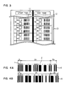
- Fig. 3 is a plan view showing a main part of a programming member for program timer recording of a first embodiment of the present invention.
- a programming member for program timer recording for use in a VTR will be described by way of example.
- a bar code ll representing START TIME of the program timer recording and a bar code l2 representing END TIME of the program timer recording are printed on a programming member for program timer recording l3 (hereinafter referred to simply as a program sheet l3) according to the present invention.
- Figs. 4A and 4B are enlarged pattern diagrams showing an example of bar codes printed on the above-mentioned program sheet l3.
- each of the bar codes contains start bits l having a length l1 and data bits 2 which have a length l2 and represent time.
- the data bits 2 in Fig. 4A represent 9:00, and the data bits 2 in Fig. 4B represent 9:30.
- Reference numeral l4 designates stop bits having a length l3 which represent the completion of a series of bar codes starting from the start bits l in Fig. 4A, and, at the same time, the stop bits l4 indicate the fact that the time represented by the data bits 2 in Fig. 4A is START TIME.
- Reference numeral l5 designates stop bits having a length l4 which represent the completion of a series of bar codes starting from the start bits l in Fig. 4B, and, at the same time, the stop bits l5 indicate the fact that the time represented by the data bits 2 in Fig. 4B is END TIME. That is, the attributes, such as the start time and the end time, of the numerical information represented by the data bits 2 are indicated by the stop bits l4 and l5, respectively. Therefore, the length of the bar codes ll and l2 shown in Fig. l3 becomes shorter than the length l of the conventional bar code shown in Fig. 2.
- each of the bar codes ll and l2 shown in Fig. 3 which respectively represent START TIME and END TIME is formed by coding a four-digit number and therefore the bar codes ll and l2 have the same code length
- the stop bits l4 of the bar code ll representing START TIME and the stop bits l5 of the bar code l2 representing END TIME are different in code from each other, so that a bar code reader (which will be described later) judges whether the time represented by the bar codes ll and l2 is the start time or the end time on the basis of the stop bits l4 and l5 and stores the respective program timer recording data, namely, the start time 9:00 and the end time 9:30, in respective storage areas of a storage circuit.
- the bar code reader can judge whether a read-out bar code represents start time data or end time data on the basis of the stop bits l4 and l5 and stores the read-out bar code in the respective storage areas of the storage circuit. Further, at the same time, the stop bits l4 and l5 make it possible to decide whether a series of bar code has completed or not.
- stop bits indicate the fact that the time represented by the data bits is the start time or the end time
- start bits it is also possible to use the start bits in order to indicate the fact that the time represented by the data bits is the start time or the end time.
- the data bits 2 may be used to represent not only numerical information indicative of time, but also numerical information indicative of a channel number of a TV as shown in Fig. 5A.
- Fig. 5A shows a bar code containing start bits l having a length l1 and data bits 20 which have a length l5 and which represent "3" in this example.
- Reference numeral 2l designates stop bits having a length l6, and the stop bits 2l simultaneously represent an attribute of numerical information of the data bits 20, namely, the stop bits 2l indicate that the data bits 20 represent a channel number.
- Fig. 5B shows an example in which the data bits represent date.
- numeral l designates start bits l having a length l1
- numeral 22 designates data bits which have a length l7 and which represent "4" in this example.
- Numeral 23 designates stop bits which have a length l8 and which simultaneously represent an attribute of numerical information of the data bits 22, namely, the stop bits 23 indicate that the data bits 22 represent a date. Therefore, Figs. 5A and 5B represent the third channel and the fourth day, respectively.
- Fig. 6 is a plan view showing a main part of a program sheet of a second embodiment of the present invention.
- numeral 30 designates a program sheet which corresponds to the program sheet l3 shown in Fig. 3 and which may be a sheet of a specific page of a magazine in which TV programs are printed.
- Reference numeral 3l designates names of broadcasting stations, 32 designates channel number, and 33 designates titles of programs, all of which are printed on the program sheet 30.
- the program sheet 30 shown in Fig. 6 is different from the program sheet l3 shown in Fig.
- the former contains the bar code 34 which includes a series of bar codes representing a channel position, date, start time and end time, and in that one channel position is assigned to one broadcasting station in all the country to thereby standardize the broadcasting program code.
- the former case there is necessarily one-to-one correspondence between the channel positions and the broadcasting stations, so that no erroneous channel selection takes place, but in the latter case, there is a possibility such that the same channel position is bar-coded with respect to a plurality of different broadcasting stations, which are listed on a program timer recording table but which have respective different reception frequencies, so that it becomes impossible to perform program timer recording of the program of a broadcasting station having a reception frequency different from that of the channel position.
- the bar code 34 formed of a series of codes including the channel position, date, start time and end time, it is made possible to complete program timer recording by performing a single time of scanning with a bar code reader. Further, if the channel position of a bar code 34 is alloted to each individual broadcasting station, it is possible to prevent erroneous channel selection from occurring while program timer recording is performed.
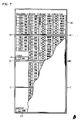
- Fig. 7 is a plan view showing a program sheet of a third embodiment of the present invention.
- a program sheet 40 made of a synthetic resin is able to be folded, for example, respectively along an A-A line, a B-B line and a C-C line shown in Fig. 7, and respective columns, CHANNEL, DATE, START TIME and END TIME, are provided in sequence from the left to the right on one surface of the sheet 40, and respective corresponding bar codes are printed in those columns.
- a bar code 4l for canceling (or resetting) program information which has once been registered (or stored), and a bar code 42 for performing image recording every day are provided on this program sheet 40.
- a rectangular mark provided on the left side of each of the bar codes is a start mark indicating a position on which a bar code reader should be placed before each bar code is scanned by the bar code reader.
- the stop bits may be provided with an attribute of each program timer recording, whereby it becomes possible to suppress a defect such that an area occupied by printing becomes large due to a possible redundant length of each bar code.
- the following table shows the relationship between the respective codes of start bits, data bits and stop bits, and various items of CHANNEL, DATE, START TIME and END TIME in the above-described embodiments of the present invention.
- Fig. 8 is a perspective view showing an example of an optical bar code reader for reading the program sheet 40 according to the present invention which is partly shown in the drawing.
- a part of the bar code sheet 40 having bar codes printed thereon is shown exaggeratedly as compared with the size of the bar code reader.
- a pen-type bar code reader 50 suitable for gripping is provided at its one end with a bar code reading section 5l comprising a light emitting section and a light receiving section, and it is provided at its opposite end with an infrared ray transmitting section 52 for emitting an infrared ray for transmitting the information, which has been read and processed by the bar code reading section 5l, into a VTR, which comprises a program timer recording subject control section, as input program timer recording information by way of a wireless system.
- the bar code reader 50 further comprises a transmission switch button 53 which is actuated when depressed to cause the infrared ray transmitting section 52 to emit an infrared ray, a power on/off switch 54 for switching on and off a battery for energizing the bar code reader 50, and a battery accommodating cover 55 for accommodating the battery within a casing of the bar code reader 50.
- the bar code reading section 5l of the bar code reader 50 having the switch 54 turned on is made to abut vertically on a start mark (designated by reference numeral 56 in Fig. 8) in the channel column 4 on the program sheet 40 in Fig. 7, and then the bar code reading section 5l is made to trace or scan a bar code 57 in the direction of an arrow F in Fig. 8, while maintaining the bar code reading section 5l to be in contact with the program sheet 40.
- the bar code 57 representing CHANNEL 4 is photoelectrically converted by the bar code reading section 5l, and the thus converted bar code is stored in a storage circuit (designated by reference numeral 58 in Fig. l0) installed in the bar code reader 50.
- DATE, START TIME and END TIME for the desired image recording are selected from the program sheet 40 and are stored in the bar code reader 50.
- the transmission switch button 53 is depressed while maintaining the infrared ray transmitting section 52 of the bar code reader 50 to face an infrared ray signal receiving section 6l of a VTR 60, as shown in Fig. 9. Then, the program timer image recording information stored in the storage circuit 58 is converted into an infrared ray signal and it is transmitted from the infrared ray transmitting section 52 to the infrared ray signal receiving section 6l of the VTR 60. In the VTR 60, the broadcasting date and the start time in the program timer image recording information transmitted to the VTR 60 are compared with the present time counted by a timer (designated by reference numeral 62 in Fig.
- a VTR control circuit (designated by reference numeral 64 in Fig. l0) is caused to select the channel position indicated by the transmitted program timer image recording information and to set the VTR 60 to the image recording mode and to control the VTR 60 to continue the program timer image recording until the program end time is reached.
- program timer recording information which has once been stored in the storage circuit 58 of the bar code reader 50 can be canceled when the storage circuit 58 is reset upon reading the bar code 4l, which is illustrated in Fig. 7 by way of example, by using the bar code reader 50.
Landscapes
- Physics & Mathematics (AREA)
- General Physics & Mathematics (AREA)
- Engineering & Computer Science (AREA)
- Theoretical Computer Science (AREA)
- Electric Clocks (AREA)
- Television Signal Processing For Recording (AREA)
- Indexing, Searching, Synchronizing, And The Amount Of Synchronization Travel Of Record Carriers (AREA)
- Circuits Of Receivers In General (AREA)
Applications Claiming Priority (4)
| Application Number | Priority Date | Filing Date | Title |
|---|---|---|---|
| JP171263/86 | 1986-07-21 | ||
| JP61171264A JPS6327128A (ja) | 1986-07-21 | 1986-07-21 | 放送番組記録機器の予約装置 |
| JP171264/86 | 1986-07-21 | ||
| JP61171263A JPS6326791A (ja) | 1986-07-21 | 1986-07-21 | バ−コ−ド形成方法 |
Publications (2)
| Publication Number | Publication Date |
|---|---|
| EP0254518A2 true EP0254518A2 (fr) | 1988-01-27 |
| EP0254518A3 EP0254518A3 (fr) | 1989-09-06 |
Family
ID=26494056
Family Applications (1)
| Application Number | Title | Priority Date | Filing Date |
|---|---|---|---|
| EP87306407A Withdrawn EP0254518A3 (fr) | 1986-07-21 | 1987-07-20 | Aide de programmation pour interrupteur horaire programmable |
Country Status (4)
| Country | Link |
|---|---|
| EP (1) | EP0254518A3 (fr) |
| KR (1) | KR900005591B1 (fr) |
| CN (1) | CN1018138B (fr) |
| AU (1) | AU7579887A (fr) |
Cited By (5)
| Publication number | Priority date | Publication date | Assignee | Title |
|---|---|---|---|---|
| WO1993008542A1 (fr) * | 1991-10-23 | 1993-04-29 | Yuen Henry C | Matrice a code barres pour grille de programmes de television |
| GB2295714A (en) * | 1994-11-22 | 1996-06-05 | Hashimoto Corp | Controlling video recorders to record and playback a preset schedule of broadcast programmes |
| GB2360114A (en) * | 2000-02-08 | 2001-09-12 | Jonathan Storbeck | Ergonomic remote control handset |
| WO2006013349A3 (fr) * | 2004-08-06 | 2006-04-20 | David Griffth | Dispositif de controle de temporisation |
| EP1016953B1 (fr) * | 1998-12-31 | 2019-07-24 | Xerox Corporation | Méthodes de sélection multi-niveau et dispositif utilisant l'identification de contexte |
Families Citing this family (1)
| Publication number | Priority date | Publication date | Assignee | Title |
|---|---|---|---|---|
| US4841132A (en) * | 1986-07-21 | 1989-06-20 | Matsushita Electric Industrial Co., Ltd. | Program recording scheduling apparatus using an optical reader |
Family Cites Families (1)
| Publication number | Priority date | Publication date | Assignee | Title |
|---|---|---|---|---|
| GB2109598B (en) * | 1981-11-04 | 1985-07-10 | Sony Corp | Controlling electronic devices |
-
1987
- 1987-07-17 AU AU75798/87A patent/AU7579887A/en not_active Abandoned
- 1987-07-20 EP EP87306407A patent/EP0254518A3/fr not_active Withdrawn
- 1987-07-21 KR KR1019870007870A patent/KR900005591B1/ko not_active Expired
- 1987-07-21 CN CN87105677A patent/CN1018138B/zh not_active Expired
Cited By (6)
| Publication number | Priority date | Publication date | Assignee | Title |
|---|---|---|---|---|
| WO1993008542A1 (fr) * | 1991-10-23 | 1993-04-29 | Yuen Henry C | Matrice a code barres pour grille de programmes de television |
| GB2295714A (en) * | 1994-11-22 | 1996-06-05 | Hashimoto Corp | Controlling video recorders to record and playback a preset schedule of broadcast programmes |
| EP1016953B1 (fr) * | 1998-12-31 | 2019-07-24 | Xerox Corporation | Méthodes de sélection multi-niveau et dispositif utilisant l'identification de contexte |
| GB2360114A (en) * | 2000-02-08 | 2001-09-12 | Jonathan Storbeck | Ergonomic remote control handset |
| GB2360114B (en) * | 2000-02-08 | 2004-12-29 | Jonathan Storbeck | New style remotes |
| WO2006013349A3 (fr) * | 2004-08-06 | 2006-04-20 | David Griffth | Dispositif de controle de temporisation |
Also Published As
| Publication number | Publication date |
|---|---|
| CN87105677A (zh) | 1988-02-10 |
| EP0254518A3 (fr) | 1989-09-06 |
| KR900005591B1 (ko) | 1990-07-31 |
| KR880002156A (ko) | 1988-04-29 |
| AU7579887A (en) | 1988-01-28 |
| CN1018138B (zh) | 1992-09-02 |
Similar Documents
| Publication | Publication Date | Title |
|---|---|---|
| US5307173A (en) | Apparatus and method using compressed codes for television program record scheduling | |
| US5974222A (en) | Apparatus and method using compressed codes for scheduling broadcast information recording | |
| US5970206A (en) | Television calendar and method for creating same | |
| EP0254517B1 (fr) | Dispositif pour l'enregistrement de programmes pour appareils électroniques | |
| US6137950A (en) | Bar code matrix television calendar | |
| US6049652A (en) | Apparatus and method using compressed codes for recorder preprogramming | |
| JPS624731B2 (fr) | ||
| GB2034995A (en) | Control of broadcast radio and television receivers | |
| CN1066357A (zh) | 盒式磁带录象机频道变换表的记录删除 | |
| CN1067147A (zh) | 带多通道及单通道信号源的盒式磁带录像机的简化设定 | |
| CN1038973C (zh) | 对盒式磁带录象机进行程序设定的自适应菜单 | |
| EP0619058B1 (fr) | Appareil et methode mettant en oeuvre des codes comprimes pour la programmation d'un enregistrement d'informations diffusees | |
| KR900005591B1 (ko) | 프로그램예약용 프로그램구성체 | |
| ATE354254T1 (de) | Empfänger für fernsehsignale mit einer elektronischen programmauswahl von verfügbaren fernsehprogrammen | |
| JPS6327128A (ja) | 放送番組記録機器の予約装置 | |
| CN1067148A (zh) | 带单通道信号源的盒式磁带录像机的简化设定 | |
| NZ243976A (en) | Video recorder remote controller transmits in at least two directions | |
| KR0178264B1 (ko) | 비데오 카셋트 레코더의 녹화 예약코드 입력방법 | |
| JPH06300871A (ja) | 情報記録装置および番組予約装置 |
Legal Events
| Date | Code | Title | Description |
|---|---|---|---|
| PUAI | Public reference made under article 153(3) epc to a published international application that has entered the european phase |
Free format text: ORIGINAL CODE: 0009012 |
|
| AK | Designated contracting states |
Kind code of ref document: A2 Designated state(s): DE FR GB NL |
|
| PUAL | Search report despatched |
Free format text: ORIGINAL CODE: 0009013 |
|
| AK | Designated contracting states |
Kind code of ref document: A3 Designated state(s): DE FR GB NL |
|
| 17P | Request for examination filed |
Effective date: 19891123 |
|
| 17Q | First examination report despatched |
Effective date: 19901024 |
|
| STAA | Information on the status of an ep patent application or granted ep patent |
Free format text: STATUS: THE APPLICATION IS DEEMED TO BE WITHDRAWN |
|
| 18D | Application deemed to be withdrawn |
Effective date: 19910305 |
|
| RIN1 | Information on inventor provided before grant (corrected) |
Inventor name: KAJITANI, MASAHIKO Inventor name: ISONO, KOJI Inventor name: TAKEDA, KIYOSHI |