EP0254594A2 - Zufuhrapparat mit Beschleunigungsmesser zur Ermittlung äusserer Störungen - Google Patents
Zufuhrapparat mit Beschleunigungsmesser zur Ermittlung äusserer Störungen Download PDFInfo
- Publication number
- EP0254594A2 EP0254594A2 EP87306590A EP87306590A EP0254594A2 EP 0254594 A2 EP0254594 A2 EP 0254594A2 EP 87306590 A EP87306590 A EP 87306590A EP 87306590 A EP87306590 A EP 87306590A EP 0254594 A2 EP0254594 A2 EP 0254594A2
- Authority
- EP
- European Patent Office
- Prior art keywords
- weight
- signal
- accelerometer
- feed rate
- acceleration
- Prior art date
- Legal status (The legal status is an assumption and is not a legal conclusion. Google has not performed a legal analysis and makes no representation as to the accuracy of the status listed.)
- Withdrawn
Links
Images

Classifications
-
- G—PHYSICS
- G01—MEASURING; TESTING
- G01G—WEIGHING
- G01G23/00—Auxiliary devices for weighing apparatus
- G01G23/18—Indicating devices, e.g. for remote indication; Recording devices; Scales, e.g. graduated
- G01G23/38—Recording and/or coding devices specially adapted for weighing apparatus
- G01G23/46—Devices preventing recording until the weighing mechanism has come to rest
-
- G—PHYSICS
- G01—MEASURING; TESTING
- G01G—WEIGHING
- G01G11/00—Apparatus for weighing a continuous stream of material during flow; Conveyor belt weighers
- G01G11/08—Apparatus for weighing a continuous stream of material during flow; Conveyor belt weighers having means for controlling the rate of feed or discharge
- G01G11/086—Apparatus for weighing a continuous stream of material during flow; Conveyor belt weighers having means for controlling the rate of feed or discharge of the loss-in-weight feeding type
-
- G—PHYSICS
- G01—MEASURING; TESTING
- G01G—WEIGHING
- G01G13/00—Weighing apparatus with automatic feed or discharge for weighing-out batches of material
- G01G13/24—Weighing mechanism control arrangements for automatic feed or discharge
- G01G13/248—Continuous control of flow of material
-
- G—PHYSICS
- G01—MEASURING; TESTING
- G01G—WEIGHING
- G01G23/00—Auxiliary devices for weighing apparatus
Definitions
- the present invention is a loss-in-weight weigh feeding system including novel means for detecting extraneous disturbances impinging on such systems and preventing them from adversely affecting the feed rate.
- the present invention is an alternative system for accomplishing the result achieved by inventions disclosed in several patents assigned to the assignee of the present invention, for example and without limitation, United States Reissue Patents Nos. 30,967, 32,101 and 32,102.
- Precise metering or feeding of solids and liquids is a task encountered in a myriad of industrial processes. Wherever material is continuously fed from a supply vessel of some sort into a production line, whether the product being manufactured is a pharmaceutical, an explosive, a food, a plastic, etc., the rate at which material is supplied must be controlled.
- a number of different types of continuous metering systems have been known for many years. Fundamentally, these are of two types: volumetric feeding systems and gravimetric feeding systems.
- a volumetric system is one that dispenses material by volume.
- Volumetric systems employ a displacement mechanism of some sort operating at a set speed (for example, an auger or a pump mounted below a supply vessel and rotating at a fixed number of revolutions per minute) which dispenses a fixed volume of material per revolution.
- Volumetric feeding systems do not monitor the actual feed rate or compare it to the desired feed rate and do not have any feedback system to correct for whatever difference might exist between those two values. If the density of the material being fed remains constant and if the material never sticks to the critical components, always moves freely and does not exhibit any other flow or handling problems, a volumetric feeder can provide reasonable accuracy. However, if actual conditions are not close to these idealized conditions, volumetric feeders can not be relied upon to produce good results. Also, since volumetric feeding systems do not detect feed rate, they are not suitable in situations where, for some reason, operational feed rate data is required.
- Gravimetric systems control the feeding of material by weight , thereby compensating for changes of density and poor product flow characteristics (e.g., stickiness, clumping, etc.). For this reason, they can provide much higher accuracy than volumetric feeders.
- Gravimetric feeding systems are of three general types: weigh-belt; weigh-auger; and loss-in-weight.
- Typical weigh-belt and weigh-auger gravimetric feeding systems measure the weight flowing across a belt or through an auger during operation, that is, while it is feeding material, and compare that weight to an expected or “set” weight, using the difference between the two to generate a control signal. While such systems offer good accuracy for many uses, material sometimes accumulates on the belt, auger or other critical components of the weighing mechanism and thereby "fools" the control system into decreasing the feed rate improperly. As will be appreciated, the problem is even worse if this accumulation builds up and falls off the belt intermittently. In short, this type of gravimetric system, while using feedback principles to offer some control, has substantial limitations that can seriously impair the accuracy-producing capabilities of the device.
- a loss-in-weight system is a weigh feeding system in which the gradual decrease in weight of the system caused by the constant release of material from its supply vessel is monitored and compared to an expected decrease in weight to assess performance. Unlike the weigh-belt and weigh-auger gravimetric systems, loss-in-weight systems are not affected by material adhering to the hopper or feed auger, since the entire system is weighed continuously. In loss-in-weight systems, a control system continually (or with great frequency) monitors a signal indicating the decreasing weight of the feed supply vessel and associated feed mechanism and adjusts the feed rate to maintain an even rate of weight loss over time.
- a loss-in-weight system For example, if a loss-in-weight system is intended to feed 60 pounds of material per hour, it should lose weight at a rate of 1 pound per minute or 7.56 grams per second. If a weight loss amount over a given time period is larger than expected as sensed by the control system, it commands the feeding mechanism to slow down. Similarly, if the weight detected becomes too high, indicating that the weight loss has been less than expected, the control system orders an increase in the material flow rate to cause the system to "catch up" with the expected feed.
- the few loss-in-weight systems that were used prior to the inventions identified above included a type of flow rate monitor generally referred to in the industry as a deviation alarm.
- a deviation alarm Such alarms, as disclosed for example in the 1951 Harkenrider patent No. 2,544,155 or the 1969 Marhauer patent No. 3,481,509, do not detect abrupt disturbances when they occur and sometimes do not detect even their aftermaths.
- a deviation alarm instead watches for long-term deviations in the flow rate (such as might be caused by the supply of material in the supply vessel running out). Such an alarm notifies the operator only after a flow rate deviation has occurred and, consequently, after material has been delivered at an improper rate, often with serious effects to the process.
- ACRILOK extraneous disturbances
- the ACRILOK technique relies on the weight signal, the same signal which had long been used in loss-in-weight systems to control the feed rate; however, it uses that weight signal in a way never before used, to solve a longstanding problem never before solved, despite its importance.
- Reissue Patent No. 30,967 discloses an analog circuit for monitoring the weight signal to detect an extraneous disturbance before it causes the discharge rate of the feeder to be distorted (that is, before the feed rate has been adjusted in a misplaced attempt to correct for the disturbance to the weight signal) and for locking the feed rate at a value independent of the disturbance until the disturbance has subsided. This timely detection and locking is accomplished, according to that patent, by monitoring the signal of weight versus time and locking the feed rate when an acceleration of that signal having a value greater than some predetermined threshold value is detected.
- the present invention is a loss-in-weight weigh feeding system in which, contrary to the systems disclosed in, for example, Reissue Patents Nos. 30,967, 32,101 and 32,102, the weight signal is not monitored to detect extraneous disturbances. Instead, according to the present invention, a separate means is used to detect an acceleration of the system indicating an extraneous disturbance and initiate a locking or other planned control of the feed rate.
- the present invention may be employed instead of the systems disclosed in the patents identified above which are assigned to the assignee of the present invention whenever, for some reason, use of the weight signal is not feasible or desirable.
- the present invention detects extraneous disturbances without monitoring the weight signal.
- an accelerometer is mounted on the loss-in-weight scale in an orientation suitable for detecting a vertical acceleration of the weighing system in either an upward or downward direction.
- the accelerometer would be mounted so that it detected an abnormal acceleration of that system in whatever direction it sensed weight changes. When such an acceleration occurs, the accelerometer output changes rapidly in response, and that output change can be detected and used to trigger a locking or other special control of the feed rate.
- FIG. 1 shows schematically a loss-in-weight weigh feeding system including an auger type feed mechanism 10 mounted on a flexure weighing system 20 like that disclosed in United States Patent No. 4,449,597.
- Feed mechanism 10 includes a dry solids hopper 11 which leads into a feed chamber 12 connected beneath it, and discharge cylinder 14 connected to the feed chamber 12 and containing within it a feed auger 13 which is driven by motor 15. Material to be metered in a controlled fashion is placed in hopper 11. Under the influence of gravity or gravity assisted by mechanical agitation, the material flows into the feed chamber 12. When motor 15 is operating, auger 13 rotates so that material is pushed from feed chamber 12 through and then out the end of the discharge cylinder 14. As indicated, the hopper and feeding mechanism are all mounted through mounting studs 24 on a weight sensing device or scale 20, here a split-beam type flexure-based system.
- the weighing device 20 is a so-called split beam type flexure scale system such as the system disclosed in Patent No. 4,449,597, which disclosure is herein incorporated by reference.
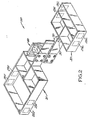
- the weighing mechanism 20 includes a balance assembly 30 comprised of upper and lower beams 31 and 32 which are joined by a flexure linkage assembly 40.
- Upper beam 31 is connected to the frame of the device by flexures shown schematically at 25U, which act as fulcrums
- lower beam 32 is similarly connected to the frame by flexures shown schematically at 25L, which also act as fulcrums.
- the weight on the scale is transmitted to the beams by studs 24 shown in Figure 1 which are connected to beam 31 through flexures shown at 26U and to beam 32 through flexures shown at 26L.
- the interconnected ends of the load-bearing beams 31 and 32 in the flexure weighing system rise as weight is applied to the system and fall when weight is removed as is described in detail in that patent and the rise and fall of beam 31 is detected by weight sensor 70 as also described in that patent. If an accelerometer 50 is mounted on beam 31 as shown, it will sense any vertical acceleration of that beam caused by an extraneous disturbance.
- accelerometer 50 is mounted on the scale in an orientation suitable for detecting a vertical acceleration of the system in either an upward or downward direction.
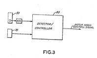
- the output signal from the accelerometer 50 is then monitored for deviation beyond limits expected in normal, undisturbed operation by detector/controller 60 which can operate in either analog or digital fashion.
- detector/controller 60 triggers a locking of the speed of motor 15 and hence, a locking of the feed rate output.
- the invention may be utilized on other weighing devices than the split beam type of flexure scale system.
- it could be used in conjunction with the flexure system disclosed in Patent No. 4,042,051 in which the weight sensor is a deflection sensing device attached near one end of a beam remote from the supply vessel.
- accelerometers are linear devices, that is, they detect accelerations along a particular axis. It is important that the accelerometer be chosen and mounted so that components of extraneous disturbances acting along the same axis as the weight sensing device are effectively detected, since it is those components of such disturbances which affect the perceived weight. While, in the present embodiment, the accelerometer is mounted so that it detects extraneous disturbances along a vertical axis - the axis of the weight sensing device employed in this embodiment - other axes might be employed.
- accelerometer 50 is mounted on the upper beam 31 close to the position of the weight sensor 70.
- the present embodiment uses a Schaevitz LSB Linear accelerometer having a range of ⁇ 1.0 g, a nominal natural frequency of 100 Hz, and a nominal output impedance of 5 kilohms, all as measured at 20 degrees Centigrade. As noted above, it has a 1-g bias so that it will sense either an upward or a downward force as is necessary with the particular weighing system discussed.
- the full-range open circuit output voltage of this device is ⁇ 5.0 volts DC giving a range of 10 volts.
- the threshold level has been found most satisfactory when set at ⁇ 2.5% of the full range voltage; in other words, the system is adjusted so that an output voltage swing of less than ⁇ 0.25 volts from the normal level does not lock the feed rate.
- the functioning of the detector/controller 60 in the present system is illustrated in Figure 3.
- the output from accelerometer 50 is first converted to digital form in an analog-to-digital convertor (ADC). Then, the resulting digital signal is compared against the preset ⁇ limits. If the signal is within the threshold limits, the system permits normal feedback control of the feed rate to continue. If, however, the signal is outside the limits, the motor updating is stopped and consequently the feed rate is locked. This locked condition persists until a comparison of the accelerometer signal with the preset limits shows that the acceleration has decreased beneath the threshold, at which point a settling timer contained within detector/controller 60 is started.
- ADC analog-to-digital convertor
- an array of three orthogonally mounted accelerometers, with their output signals suitable combined, could be installed on a system to detect accelerations in any direction including a direction indicating an extraneous disturbance affecting the weight signal relied upon for control purposes.
- accelerometers devices commonly referred to as accelerometers are described herein, that term as used in the specification and specifically the claims herein is also intended to encompass other means - not connected to the weight sensing means - for detecting accelerations.
- a laser beam associated with the weigh feeding system could be aimed at one or more reflecting surfaces separate from the system, and the reflected light could be monitored to detect accelerations of the system without departing from the scope of the present invention.
Landscapes
- Physics & Mathematics (AREA)
- General Physics & Mathematics (AREA)
- Weight Measurement For Supplying Or Discharging Of Specified Amounts Of Material (AREA)
- Feeding Of Articles To Conveyors (AREA)
- Mechanical Treatment Of Semiconductor (AREA)
- Valve Device For Special Equipments (AREA)
- Control Of The Air-Fuel Ratio Of Carburetors (AREA)
Applications Claiming Priority (2)
| Application Number | Priority Date | Filing Date | Title |
|---|---|---|---|
| US889471 | 1986-07-25 | ||
| US06/889,471 US4722456A (en) | 1986-07-25 | 1986-07-25 | With accelerometer for detecting extraneous disturbances weigh feeder |
Publications (2)
| Publication Number | Publication Date |
|---|---|
| EP0254594A2 true EP0254594A2 (de) | 1988-01-27 |
| EP0254594A3 EP0254594A3 (de) | 1989-06-28 |
Family
ID=25395171
Family Applications (1)
| Application Number | Title | Priority Date | Filing Date |
|---|---|---|---|
| EP87306590A Withdrawn EP0254594A3 (de) | 1986-07-25 | 1987-07-24 | Zufuhrapparat mit Beschleunigungsmesser zur Ermittlung äusserer Störungen |
Country Status (4)
| Country | Link |
|---|---|
| US (1) | US4722456A (de) |
| EP (1) | EP0254594A3 (de) |
| JP (1) | JPS6375522A (de) |
| CA (1) | CA1274604A (de) |
Cited By (1)
| Publication number | Priority date | Publication date | Assignee | Title |
|---|---|---|---|---|
| EP2159554A1 (de) * | 2008-08-29 | 2010-03-03 | Mettler-Toledo AG | Verfahren zur Zustandsüberwachung einer Kraftmessvorrichtung, Kraftmessvorrichtung und Kraftmessmodul |
Families Citing this family (11)
| Publication number | Priority date | Publication date | Assignee | Title |
|---|---|---|---|---|
| US4804111A (en) * | 1987-02-20 | 1989-02-14 | Acrison, Inc. | Mechanism for metering solid materials which flow in a manner similar to liquids |
| US5260880A (en) * | 1987-08-04 | 1993-11-09 | Accurate, Inc. | Loss-in-weight feeder system |
| DE3812567A1 (de) * | 1988-04-15 | 1989-10-26 | Basf Ag | Verfahren zur herstellung pharmazeutischer mischungen |
| DE3938898A1 (de) * | 1989-11-24 | 1991-05-29 | Sartorius Gmbh | Verfahren und vorrichtung zum pulsationsfreien kontinuierlichen gravimetrischen dosieren |
| DE4116331C2 (de) * | 1991-05-17 | 1994-07-07 | Schenck Ag Carl | Dosiervorrichtung für Schüttgüter und Flüssigkeiten |
| US20020084293A1 (en) | 2001-01-02 | 2002-07-04 | Liad Weighing And Control Systems Ltd. | System for feeding portions of material to an injection molding machine |
| FR2874211B1 (fr) * | 2004-08-10 | 2006-10-20 | Movidis Sa | Dispositif de transfert et de dosage de matiere pulverulente ou granuleuse contenue dans une tremie |
| US7534970B2 (en) * | 2006-06-15 | 2009-05-19 | Schenck Accurate, Inc. | Counterbalanced dispensing system |
| US7660648B2 (en) * | 2007-01-10 | 2010-02-09 | Halliburton Energy Services, Inc. | Methods for self-balancing control of mixing and pumping |
| US10288472B2 (en) * | 2016-11-15 | 2019-05-14 | Digi-Star, Llc | Method and apparatus for compensation of wind effects on measured weights |
| DE102020209530A1 (de) * | 2020-07-29 | 2022-02-03 | Ford Global Technologies, Llc | Lagersystem für einen Laderaum eines Nutzkraftwagens und Verfahren zum Überwachen einer Stückzahl und/oder eines Volumens eines in einer Aufnahmeeinheit in einem Nutzkraftwagen befindlichen Guts |
Family Cites Families (10)
| Publication number | Priority date | Publication date | Assignee | Title |
|---|---|---|---|---|
| US32102A (en) * | 1861-04-16 | James dodge | ||
| US30967A (en) * | 1860-12-18 | Improvement in gang-plows | ||
| US32101A (en) * | 1861-04-16 | Beehive | ||
| USRE30967E (en) | 1972-07-25 | 1982-06-15 | Acrison, Inc. | Automatically controlled weigh feeding apparatus |
| US3889848A (en) * | 1972-07-25 | 1975-06-17 | Ronald J Ricciardi | Automatically controlled weigh feeding apparatus |
| USRE32102E (en) | 1976-04-19 | 1986-04-01 | Acrison, Inc. | Weigh feeding apparatus |
| USRE32101E (en) | 1976-12-07 | 1986-04-01 | Acrison, Inc. | Weigh feeding apparatus |
| US4449597A (en) * | 1982-04-23 | 1984-05-22 | Acrison, Incorporated | Flexure weighing system |
| DE3230998C2 (de) * | 1982-08-20 | 1986-10-02 | Mettler-Waagen Gmbh, 6300 Giessen | Wägezelle |
| JPS6011119A (ja) * | 1983-06-30 | 1985-01-21 | Shimadzu Corp | 電子天びん |
-
1986
- 1986-07-25 US US06/889,471 patent/US4722456A/en not_active Expired - Fee Related
-
1987
- 1987-07-21 CA CA000542575A patent/CA1274604A/en not_active Expired - Fee Related
- 1987-07-24 EP EP87306590A patent/EP0254594A3/de not_active Withdrawn
- 1987-07-25 JP JP62184705A patent/JPS6375522A/ja active Pending
Cited By (3)
| Publication number | Priority date | Publication date | Assignee | Title |
|---|---|---|---|---|
| EP2159554A1 (de) * | 2008-08-29 | 2010-03-03 | Mettler-Toledo AG | Verfahren zur Zustandsüberwachung einer Kraftmessvorrichtung, Kraftmessvorrichtung und Kraftmessmodul |
| WO2010023287A1 (de) * | 2008-08-29 | 2010-03-04 | Mettler-Toledo Ag | Verfahren zur zustandsüberwachung einer kraftmessvorrichtung, kraftmessvorrichtung und kraftmessmodul |
| RU2503933C2 (ru) * | 2008-08-29 | 2014-01-10 | Меттлер-Толедо Аг | Способ контроля устройства измерения силы, устройство измерения силы и модуль измерения силы |
Also Published As
| Publication number | Publication date |
|---|---|
| US4722456A (en) | 1988-02-02 |
| EP0254594A3 (de) | 1989-06-28 |
| CA1274604A (en) | 1990-09-25 |
| JPS6375522A (ja) | 1988-04-05 |
Similar Documents
| Publication | Publication Date | Title |
|---|---|---|
| US4722456A (en) | With accelerometer for detecting extraneous disturbances weigh feeder | |
| US4762252A (en) | Adaptation to major or sporadic disturbance error in weigh feeding apparatus | |
| US4867343A (en) | Wild-flow loss-in-weight weighing system | |
| US5533392A (en) | System and method for sensing material level within a container | |
| US4210963A (en) | Weigh feeder system | |
| US4320855A (en) | Weigh feeding apparatus | |
| EP0631115B1 (de) | Differentialdosierwaage mit Messung der Schüttdichte durch Füllstandsbestimmung | |
| USRE32101E (en) | Weigh feeding apparatus | |
| US4418773A (en) | Conveyor calibration technique | |
| US4843579A (en) | Weighing and filling method and apparatus | |
| KR910005301B1 (ko) | 연속 계량기에 의한 연속 벌크물질 생산량의 자동측정장치 | |
| US5938074A (en) | Metering method and metering device for powder materials | |
| EP0279353A1 (de) | Dosiereinrichtung für feste Stoffe, die wie Flüssigkeiten strömen | |
| USRE32102E (en) | Weigh feeding apparatus | |
| CA1275863C (en) | Apparatus and method for feeding particulate material such as coal and other bulk materials | |
| JPH06502913A (ja) | バルク材料のための重力式計量装置 | |
| EP0092410A2 (de) | Zyklisches Wiegen von Festkörpermaterial | |
| CN212923627U (zh) | 一种用于水泥熟料一卡通装车系统 | |
| US20040002789A1 (en) | Loss-in-weight feeder with discharge pressure compensator | |
| CA1094039A (en) | Weigh feeder system | |
| DE19739712A1 (de) | Verfahren und Vorrichtung zur kontinuierlichen, gravimetrischen Dosierung | |
| US4750576A (en) | Continuous flow weighing apparatus | |
| CN104874332B (zh) | 一种化工生产用自动加料系统 | |
| CN221025672U (zh) | 配煤计量系统 | |
| US1397932A (en) | Feeding apparatus for weighing-machines and the like |
Legal Events
| Date | Code | Title | Description |
|---|---|---|---|
| PUAI | Public reference made under article 153(3) epc to a published international application that has entered the european phase |
Free format text: ORIGINAL CODE: 0009012 |
|
| AK | Designated contracting states |
Kind code of ref document: A2 Designated state(s): CH DE FR GB IT LI NL |
|
| PUAL | Search report despatched |
Free format text: ORIGINAL CODE: 0009013 |
|
| RHK1 | Main classification (correction) |
Ipc: G01G 11/08 |
|
| AK | Designated contracting states |
Kind code of ref document: A3 Designated state(s): CH DE FR GB IT LI NL |
|
| 17P | Request for examination filed |
Effective date: 19891222 |
|
| 17Q | First examination report despatched |
Effective date: 19901214 |
|
| STAA | Information on the status of an ep patent application or granted ep patent |
Free format text: STATUS: THE APPLICATION IS DEEMED TO BE WITHDRAWN |
|
| 18D | Application deemed to be withdrawn |
Effective date: 19920317 |
|
| RIN1 | Information on inventor provided before grant (corrected) |
Inventor name: RICCIARDI, RONALD J. Inventor name: LAIDLAW, JOHN Inventor name: KAHN, STEPHEN D. |