EP0254708A2 - Appareil ménager avec dispositif électrique de freinage - Google Patents
Appareil ménager avec dispositif électrique de freinage Download PDFInfo
- Publication number
- EP0254708A2 EP0254708A2 EP87890109A EP87890109A EP0254708A2 EP 0254708 A2 EP0254708 A2 EP 0254708A2 EP 87890109 A EP87890109 A EP 87890109A EP 87890109 A EP87890109 A EP 87890109A EP 0254708 A2 EP0254708 A2 EP 0254708A2
- Authority
- EP
- European Patent Office
- Prior art keywords
- motor
- braking
- frequency converter
- direct current
- brake
- Prior art date
- Legal status (The legal status is an assumption and is not a legal conclusion. Google has not performed a legal analysis and makes no representation as to the accuracy of the status listed.)
- Withdrawn
Links
Images
Classifications
-
- D—TEXTILES; PAPER
- D06—TREATMENT OF TEXTILES OR THE LIKE; LAUNDERING; FLEXIBLE MATERIALS NOT OTHERWISE PROVIDED FOR
- D06F—LAUNDERING, DRYING, IRONING, PRESSING OR FOLDING TEXTILE ARTICLES
- D06F37/00—Details specific to washing machines covered by groups D06F21/00 - D06F25/00
- D06F37/30—Driving arrangements
- D06F37/304—Arrangements or adaptations of electric motors
-
- Y—GENERAL TAGGING OF NEW TECHNOLOGICAL DEVELOPMENTS; GENERAL TAGGING OF CROSS-SECTIONAL TECHNOLOGIES SPANNING OVER SEVERAL SECTIONS OF THE IPC; TECHNICAL SUBJECTS COVERED BY FORMER USPC CROSS-REFERENCE ART COLLECTIONS [XRACs] AND DIGESTS
- Y02—TECHNOLOGIES OR APPLICATIONS FOR MITIGATION OR ADAPTATION AGAINST CLIMATE CHANGE
- Y02B—CLIMATE CHANGE MITIGATION TECHNOLOGIES RELATED TO BUILDINGS, e.g. HOUSING, HOUSE APPLIANCES OR RELATED END-USER APPLICATIONS
- Y02B40/00—Technologies aiming at improving the efficiency of home appliances, e.g. induction cooking or efficient technologies for refrigerators, freezers or dish washers
Definitions
- the invention relates to a household machine, in particular a washing machine, with a frequency converter-controlled three-phase asynchronous motor as the drive, and with an electrical braking device for accelerating the shutdown of the motor after switching off the power supply, which is connected to at least two power transistors of the three-phase bridge of the frequency converter arranged in different bridge branches Has brake electronics.
- the present invention has for its object to provide a way to shorten the time that elapses after switching off the power supply to the drive motor until the machine comes to a standstill using simple and inexpensive means.
- a mechanical braking device acting on the drive motor or, for example, also on the laundry drum or another part of the drive system which is obvious in this context, is prohibited in the household machines in question as a result of the associated increased costs and is also of interest on the environmental impact of abrasion of brake pads problematic.
- a machine designed as a screwdriver of the type mentioned at the beginning, in which an electric braking device is already provided, is known, for example, from DE-A-3l 5l 625, where it is explicitly pointed out that braking takes place via a special braking program in which the phase sequence is tracked in a counter and the braking program that matches the current-carrying phase is called up from a memory when the braking command is given.
- the braking process itself is achieved by reducing the supply frequency and over-synchronous braking.
- over-synchronous braking can lead to a critical rise in the DC link and ultimately damage to the power semiconductors.
- the above-mentioned objects are achieved in that the brake electronics open the connected transistors during braking and thus serve to introduce direct current into the motor.
- braking is therefore carried out in a simple manner with direct current generated by opening the transistors connected to the brake electronics, thus avoiding the disadvantages mentioned without additional components.
- the three-phase bridge for controlling the three-phase asynchronous motor in the frequency converter is put into a specific, defined state after the power supply has been switched off - i.e. after all six power transistors have been blocked.
- the three-phase bridge is no longer continuously reversed, so that for the Operation of the motor to generate the necessary rotating field, but it is de facto stopped at a certain point via the brake electronics, which corresponds to a "frequency 0", with which direct current is forced into the three-phase asynchronous motor and a braking torque is generated.
- the drive motor and thus, for example, the washing drum of a washing machine can be brought to a standstill very quickly and easily.
- the direct current that can be generated via the brake electronics can be adjustable for braking the motor by chopper operation of the controlled power transistors, which allows simple regulation of the braking effect.
- the invention also avoids the negative effects of the possibility of regenerative braking, which also exists per se, but which occur seriously in connection with the frequency converter.
- the drive motor would feed energy into the DC link of the frequency converter during generator operation, the voltage of which would then rise, which would ultimately exceed the reverse voltage of the power transistors.
- additional power components would have to be provided which would further increase the effort and thus the costs. Counter-current braking would have similar consequences.
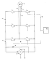
- a three-phase asynchronous motor 1 which is used to drive a household machine (not shown further), such as a washing machine, is connected to the three-phase bridge 5 of a frequency converter 6 via supply lines 2, 3, 4.
- the frequency converter 6 has a DC voltage intermediate circuit and is supplied on the input side with a rectifier 7 with rectified voltage from the AC network.
- a filter capacitor 8 is also arranged in parallel with the DC voltage connections of the rectifier 7.
- the six power transistors 9 of the three-phase bridge 5 can be continuously reversed from control electronics in a manner not shown here, so that the rotating field required for the operation of the motor 1 is generated from the DC voltage of the intermediate circuit in a known and not of further interest.
- Lines l0, ll connect two power transistors 9 arranged in different bridge branches - here the upper left and lower right - regardless of their connection to the control electronics required for generating the rotating field, they are connected to brake electronics l2, which have no function during normal operation of the motor l has and only functions when or after switching off the power supply. Then - if otherwise all six power transistors would be closed - the two controlled by it are kept open via the brake electronics l2, so that practically the rotating field is stopped at a certain point and direct current is forced into the motor l via the supply lines 2 and 4. A braking torque is thus generated which can also be controlled by chopper operation of the two controlled power transistors 9.
- the brake electronics l2 could of course also be implemented in an electronic assembly or the like which also serves to control the rotating field in normal operation of the motor l and which then simply performs another function for the braking operation.
Landscapes
- Engineering & Computer Science (AREA)
- Textile Engineering (AREA)
- Stopping Of Electric Motors (AREA)
- Control Of Washing Machine And Dryer (AREA)
Applications Claiming Priority (2)
| Application Number | Priority Date | Filing Date | Title |
|---|---|---|---|
| AT1422/86 | 1986-05-27 | ||
| AT0142286A AT391780B (de) | 1986-05-27 | 1986-05-27 | Haushaltsmaschine, insbesondere waschmaschine |
Publications (2)
| Publication Number | Publication Date |
|---|---|
| EP0254708A2 true EP0254708A2 (fr) | 1988-01-27 |
| EP0254708A3 EP0254708A3 (fr) | 1988-05-04 |
Family
ID=3513557
Family Applications (1)
| Application Number | Title | Priority Date | Filing Date |
|---|---|---|---|
| EP87890109A Withdrawn EP0254708A3 (fr) | 1986-05-27 | 1987-05-20 | Appareil ménager avec dispositif électrique de freinage |
Country Status (3)
| Country | Link |
|---|---|
| EP (1) | EP0254708A3 (fr) |
| AT (1) | AT391780B (fr) |
| DK (1) | DK267387A (fr) |
Cited By (2)
| Publication number | Priority date | Publication date | Assignee | Title |
|---|---|---|---|---|
| EP0346793A1 (fr) * | 1988-06-13 | 1989-12-20 | INDUSTRIE ZANUSSI S.p.A. | Moyen pour arrêter rapidement la rotation du moteur d'un lave-linge ou d'un lave-linge combiné avec un sèche-linge pour une blanchisserie |
| DE102008000146A1 (de) * | 2008-01-25 | 2009-07-30 | Zf Friedrichshafen Ag | Verfahren und Anordnung zum Ansteuern eines elektrischen Antriebes |
Family Cites Families (5)
| Publication number | Priority date | Publication date | Assignee | Title |
|---|---|---|---|---|
| DE1638611C3 (de) * | 1967-09-29 | 1975-03-06 | Siemens Ag, 1000 Berlin U. 8000 Muenchen | Anordnung zum Bremsen einer Drehfeldmaschine |
| DE2508497B2 (de) * | 1975-02-27 | 1977-01-20 | Verfahren zum abbremsen mit gleichstrom von mehreren parallelgeschalteten hysteresemotoren einer anlage | |
| FR2442291A1 (fr) * | 1978-11-24 | 1980-06-20 | Esswein Sa | Procede d'arret du tambour d'une machine a laver, systeme de mise en oeuvre de ce procede, et machine a laver comportant un tel systeme |
| DE3275393D1 (en) * | 1981-12-18 | 1987-03-12 | Cerac Inst Sa | Washing machine |
| DE3151625A1 (de) * | 1981-12-28 | 1983-07-07 | Dr. Staiger, Mohilo + Co GmbH, 7060 Schorndorf | Frequenzumrichter zur steuerung von asynchronmotoren, insbesondere zum einsatz bei automatischen schraubeinrichtungen |
-
1986
- 1986-05-27 AT AT0142286A patent/AT391780B/de not_active IP Right Cessation
-
1987
- 1987-05-20 EP EP87890109A patent/EP0254708A3/fr not_active Withdrawn
- 1987-05-26 DK DK267387A patent/DK267387A/da not_active Application Discontinuation
Cited By (2)
| Publication number | Priority date | Publication date | Assignee | Title |
|---|---|---|---|---|
| EP0346793A1 (fr) * | 1988-06-13 | 1989-12-20 | INDUSTRIE ZANUSSI S.p.A. | Moyen pour arrêter rapidement la rotation du moteur d'un lave-linge ou d'un lave-linge combiné avec un sèche-linge pour une blanchisserie |
| DE102008000146A1 (de) * | 2008-01-25 | 2009-07-30 | Zf Friedrichshafen Ag | Verfahren und Anordnung zum Ansteuern eines elektrischen Antriebes |
Also Published As
| Publication number | Publication date |
|---|---|
| DK267387D0 (da) | 1987-05-26 |
| DK267387A (da) | 1987-11-28 |
| EP0254708A3 (fr) | 1988-05-04 |
| ATA142286A (de) | 1990-05-15 |
| AT391780B (de) | 1990-11-26 |
Similar Documents
| Publication | Publication Date | Title |
|---|---|---|
| DE2521940C2 (de) | Schaltungsanordnung zum Steuern von Elektromotoren einer Spinnereimaschine | |
| DE3535895A1 (de) | Elektrische betaetigungsvorrichtung, insbesonder fuer ventile | |
| DE112018006737T5 (de) | Leistungswandlungsvorrichtung | |
| DE3801478C1 (fr) | ||
| DE3641569C1 (en) | Circuit arrangement for spinning or twisting machines | |
| DE68906970T2 (de) | Steuermittel fuer einen elektrischen universalmotor. | |
| DE10146523A1 (de) | Antriebssteuereinrichtung für einen stromrichtergespeisten, mehrphasigen Motor | |
| EP0045951B1 (fr) | Procédé pour mettre en marche un convertisseur ayant un circuit intermédiaire à courant continu alimentant un moteur électrique synchrone | |
| DE4128803A1 (de) | Frequenzumrichter | |
| AT391780B (de) | Haushaltsmaschine, insbesondere waschmaschine | |
| EP0514580B1 (fr) | Convertisseur | |
| DE2425362A1 (de) | Drehzahlveraenderliche elektrische antriebseinrichtung mit nutzbremsmoeglichkeit | |
| DE10018774B4 (de) | Verfahren und Schaltungsanordnung zum lagegeregelten Stillsetzen von rotierenden Bauteilen bei wellenlosen Antrieben bei Spannungsausfall | |
| CH660652A5 (de) | Wechselrichter-anordnung. | |
| EP2088488B1 (fr) | Dispositif d'entraînement et son procédé de fonctionnement | |
| DE3929407C2 (fr) | ||
| DE102004042256A1 (de) | Gleichspannungszwischenkreis | |
| DE4333733A1 (de) | Schaltungsanordnung zum Abbremsen eines Stromwendermotors | |
| DE112011105118T5 (de) | Wechselstrom-Motorantriebsvorrichtung | |
| DE102015210001A1 (de) | Bremsschaltung im AC Motorstromkreis | |
| EP1927686B1 (fr) | Métiers à tisser dotés d'un actionnement électrique | |
| EP1554796A1 (fr) | Procede pour faire demarrer un ensemble a arbre et dispositif pour la mise en oeuvre de ce procede | |
| DE10159645B4 (de) | Verfahren und Vorrichtung zur Aufrechterhaltung einer Versorgungsspannung einer Stromversorgung einer Elektronik eines Matrixumrichters bei Netzunterbrechung | |
| DE4118829C2 (de) | Verfahren zum Betrieb einer Spinnereimaschine und Vorrichtung zur Durchführung des Verfahrens | |
| DE102006032476A1 (de) | Verluststrombegrenzung im Gleichspannungszwischenkreis |
Legal Events
| Date | Code | Title | Description |
|---|---|---|---|
| PUAI | Public reference made under article 153(3) epc to a published international application that has entered the european phase |
Free format text: ORIGINAL CODE: 0009012 |
|
| AK | Designated contracting states |
Kind code of ref document: A2 Designated state(s): BE CH DE ES FR GB IT LI NL SE |
|
| PUAL | Search report despatched |
Free format text: ORIGINAL CODE: 0009013 |
|
| AK | Designated contracting states |
Kind code of ref document: A3 Designated state(s): BE CH DE ES FR GB IT LI NL SE |
|
| 17P | Request for examination filed |
Effective date: 19880926 |
|
| 17Q | First examination report despatched |
Effective date: 19900821 |
|
| STAA | Information on the status of an ep patent application or granted ep patent |
Free format text: STATUS: THE APPLICATION IS DEEMED TO BE WITHDRAWN |
|
| 18D | Application deemed to be withdrawn |
Effective date: 19910423 |
|
| RIN1 | Information on inventor provided before grant (corrected) |
Inventor name: MAZUHELI ROBERT ING. Inventor name: BECKORD ULRICH DIPL.ING. |