EP0255076B1 - Dispositif d'ouverture pour des portes coulissantes qui se chevauchent et sont guidées par des glissières parallèles sur des cabines de machines-outils - Google Patents
Dispositif d'ouverture pour des portes coulissantes qui se chevauchent et sont guidées par des glissières parallèles sur des cabines de machines-outils Download PDFInfo
- Publication number
- EP0255076B1 EP0255076B1 EP87110825A EP87110825A EP0255076B1 EP 0255076 B1 EP0255076 B1 EP 0255076B1 EP 87110825 A EP87110825 A EP 87110825A EP 87110825 A EP87110825 A EP 87110825A EP 0255076 B1 EP0255076 B1 EP 0255076B1
- Authority
- EP
- European Patent Office
- Prior art keywords
- cylinders
- opening device
- cylinder
- sliding
- gate
- Prior art date
- Legal status (The legal status is an assumption and is not a legal conclusion. Google has not performed a legal analysis and makes no representation as to the accuracy of the status listed.)
- Expired - Lifetime
Links
- 108010066278 cabin-4 Proteins 0.000 description 2
Images
Classifications
-
- F—MECHANICAL ENGINEERING; LIGHTING; HEATING; WEAPONS; BLASTING
- F16—ENGINEERING ELEMENTS AND UNITS; GENERAL MEASURES FOR PRODUCING AND MAINTAINING EFFECTIVE FUNCTIONING OF MACHINES OR INSTALLATIONS; THERMAL INSULATION IN GENERAL
- F16P—SAFETY DEVICES IN GENERAL; SAFETY DEVICES FOR PRESSES
- F16P3/00—Safety devices acting in conjunction with the control or operation of a machine; Control arrangements requiring the simultaneous use of two or more parts of the body
- F16P3/08—Safety devices acting in conjunction with the control or operation of a machine; Control arrangements requiring the simultaneous use of two or more parts of the body in connection with the locking of doors, covers, guards, or like members giving access to moving machine parts
-
- B—PERFORMING OPERATIONS; TRANSPORTING
- B23—MACHINE TOOLS; METAL-WORKING NOT OTHERWISE PROVIDED FOR
- B23Q—DETAILS, COMPONENTS, OR ACCESSORIES FOR MACHINE TOOLS, e.g. ARRANGEMENTS FOR COPYING OR CONTROLLING; MACHINE TOOLS IN GENERAL CHARACTERISED BY THE CONSTRUCTION OF PARTICULAR DETAILS OR COMPONENTS; COMBINATIONS OR ASSOCIATIONS OF METAL-WORKING MACHINES, NOT DIRECTED TO A PARTICULAR RESULT
- B23Q11/00—Accessories fitted to machine tools for keeping tools or parts of the machine in good working condition or for cooling work; Safety devices specially combined with or arranged in, or specially adapted for use in connection with, machine tools
- B23Q11/08—Protective coverings for parts of machine tools; Splash guards
-
- F—MECHANICAL ENGINEERING; LIGHTING; HEATING; WEAPONS; BLASTING
- F16—ENGINEERING ELEMENTS AND UNITS; GENERAL MEASURES FOR PRODUCING AND MAINTAINING EFFECTIVE FUNCTIONING OF MACHINES OR INSTALLATIONS; THERMAL INSULATION IN GENERAL
- F16C—SHAFTS; FLEXIBLE SHAFTS; ELEMENTS OR CRANKSHAFT MECHANISMS; ROTARY BODIES OTHER THAN GEARING ELEMENTS; BEARINGS
- F16C29/00—Bearings for parts moving only linearly
- F16C29/08—Arrangements for covering or protecting the ways
-
- F—MECHANICAL ENGINEERING; LIGHTING; HEATING; WEAPONS; BLASTING
- F16—ENGINEERING ELEMENTS AND UNITS; GENERAL MEASURES FOR PRODUCING AND MAINTAINING EFFECTIVE FUNCTIONING OF MACHINES OR INSTALLATIONS; THERMAL INSULATION IN GENERAL
- F16C—SHAFTS; FLEXIBLE SHAFTS; ELEMENTS OR CRANKSHAFT MECHANISMS; ROTARY BODIES OTHER THAN GEARING ELEMENTS; BEARINGS
- F16C2322/00—Apparatus used in shaping articles
- F16C2322/39—General buildup of machine tools, e.g. spindles, slides, actuators
Definitions
- the invention relates to an opening device for overlapping sliding gates guided on parallel guideways of machine tools, with cylinders with piston rods arranged in pairs to the side of the gates.
- Such opening devices are known for the sliding gates of machine tool cabins.
- the devices used here have telescopic lifting cylinders. -
- US-A 3 871 437 discloses an opening device for gates guided on parallel guideways of machine tools.
- a lifting cylinder is used on both sides of the opening, which adjusts the individual gates one after the other, similar to the stepped, telescopically arranged piston rods of a lifting cylinder.
- This device also results in an opening time which corresponds to the movement of the head of the piston rod over its entire path.
- the known lifting devices are either structurally complex and therefore expensive, or else, as stated, they require a time that is unsuitable for a quick opening and closing of the sliding gates.
- the object of the invention is therefore to provide an opening device of the type mentioned at the outset with structurally simple means which allows the sliding gates to be opened and closed quickly and takes up little space and is easy to maintain.
- the invention provides the features of the characterizing part of the main claim, the features of the subclaims serve to improve and further develop the device according to the main claim.
- the invention is based on the idea of using the stationary cylinder or cylinders not only to move the associated sliding gate, but also to move the cylinder or cylinders with it, so that the one or two cylinders at the same height have a relative speed opposite the other sliding gate.
- the speed of movement of one sliding gate is twice as high as that of the other sliding gate.
- the sliding gates simultaneously reach their upper and lower end positions.
- the cylinders can be located either inside the machine tool cabin or outside the cabin.
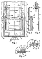
- the two sliding gates 1, 2 close the opening 3 of a machine tool booth 4, the two sliding gates being guided in the vertical direction on corresponding guides on both sides of the opening.
- a vertical lifting cylinder 8 On both sides of the lower sliding gate 1 and the corresponding opening section in the front wall of the cabin 4, a vertical lifting cylinder 8 is arranged, the piston rod 9 of which protrudes from the cylinder at the upper end and there by means of a crossbeam or web 10 with the lower edge 2a of the upper sliding gate 2 is connected.
- a cylinder 11 On the inside of the sliding gate 2 in the vicinity of its leading edges 2b and at the level of the gate, a cylinder 11 is attached, the upper and lower ends of the cylinder being firmly connected to the lower gate edge 2a and the upper gate edge 2c.
- the piston rod 12 of the piston 11 is directed downwards and its end 13 is connected to the lower end 1 a of the lower sliding gate 1 via a cross member or a web 14.
- a cross member or a web 14 As can be seen from Figure 1, the arrangement of the cylinders and the connection of their piston rod with the sliding gates is provided in mirror image to the central plane M of the cabin or the front wall thereof.
- the sliding gate 1 are assigned to the cylinders 8 on both sides, i. H. these are at the same level; the sliding gate 2, the cylinders 11 are assigned in a corresponding manner.
- the mode of operation of the device can be seen from FIG.
- the piston rod 9 extends out of the cylinder 8
- the cylinder 11 and the upper gate 2 connected to it have the speed V.
- the piston rod 12 of the cylinder 11 gives the lower sliding gate 1 a further speed V in addition to this speed V, so that the lower gate 1 lifts at twice the speed of gate 2 and both gates move from the position shown in FIG. 2 to the position shown in FIG. 3 at the same time, since the sliding gates have the same or approximately the same height H and the cylinders 8, 11 have the same or approximately the same lifting height to have; the cross section of both cylinders can also be the same.
- the lower cylinder 8 Press the upper gate 2 upwards, the cylinders 11 pull the lower gate 1 into the position according to FIG. 3.
- FIG. 4 shows the attack of the piston rod 9 on the upper gate 2.
- the wall 5 for the upper gate 2 has a longitudinal slot 15 through which the web 10 of the piston rod 9 acting on the upper gate can protrude.
- - Figure 5 shows the passage of the web 10 through the front wall 16 of the cabin.
- the respective lower end of the cylinders 8, 11 is connected to a line 22 via branches 22a, 22b with a three-way valve 20, while the upper end is connected to a line 21 via branches 21a, 21b to this valve.
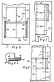
- two lifting cylinders 25, 26 are again provided on the side of the lower gate 24, the piston rods 27, 28 of which are connected to the lower section 23a of the upper sliding gate 23 via the web 29 is.
- a central cylinder 30 is now arranged, the piston rod 31 of which engages the lower section 24a of the gate 24.
- the lower gate 24 is the pair of cylinders 25, 26; assigned to the upper gate 23 of the central cylinder 30.
- the cylinders 25, 26 push the upper gate 23 upwards, the cylinder 30 pulls the lower gate 24 upwards.
- Fig. 7 illustrates two sliding gates 32, 33, of which the upper sliding gate 32 is raised and lowered with the aid of stationary lifting cylinders 34 and is provided with cylinders 35, the piston rods 36 of which engage the lower section 33a of the lower sliding gate 33.
- the cylinder 32 is assigned to the gate 32, the cylinder 33 to the cylinder 33.
- the cylinders 34 press, the cylinders 35 pull their gates 32, 33 into their end position.
- FIG. 8 shows that the principle according to the invention can also be used with more than two sliding gates, where the three sliding gates 37, 38, 39 can be opened and closed.
- the gates 37, 38 and their cylinders 40, 41 with their piston rods 42, 43 are arranged like parts 1, 2 and 11, 12 according to FIG. 1.
- the third cylinder 44 is now attached to the middle gate 38, the piston rod 45 of which engages the lower section 39a of the lower gate 39.
- one of the two cylinders 8, 11 is arranged outside and the other cylinder inside the machine tool cabin, in FIG. 9 both cylinders 46, 47 of the gates 48, 49 are provided outside the cabin 4.
- Any combination of the arrangement can be selected for the arrangement of the cylinders, and the placement of the cylinders and their connection to the sliding gates can be varied.
Landscapes
- Engineering & Computer Science (AREA)
- General Engineering & Computer Science (AREA)
- Mechanical Engineering (AREA)
- Barrages (AREA)
- Actuator (AREA)
- Power-Operated Mechanisms For Wings (AREA)
Claims (7)
Applications Claiming Priority (2)
| Application Number | Priority Date | Filing Date | Title |
|---|---|---|---|
| DE19863625544 DE3625544A1 (de) | 1986-07-29 | 1986-07-29 | Oeffnungseinrichtung fuer sich ueberlappende, an parallelen fuehrungsbahnen von werkzeugmaschinenkabinen gefuehrte schiebetore |
| DE3625544 | 1986-07-29 |
Publications (2)
| Publication Number | Publication Date |
|---|---|
| EP0255076A1 EP0255076A1 (fr) | 1988-02-03 |
| EP0255076B1 true EP0255076B1 (fr) | 1990-01-31 |
Family
ID=6306165
Family Applications (1)
| Application Number | Title | Priority Date | Filing Date |
|---|---|---|---|
| EP87110825A Expired - Lifetime EP0255076B1 (fr) | 1986-07-29 | 1987-07-25 | Dispositif d'ouverture pour des portes coulissantes qui se chevauchent et sont guidées par des glissières parallèles sur des cabines de machines-outils |
Country Status (2)
| Country | Link |
|---|---|
| EP (1) | EP0255076B1 (fr) |
| DE (3) | DE3625544A1 (fr) |
Families Citing this family (6)
| Publication number | Priority date | Publication date | Assignee | Title |
|---|---|---|---|---|
| DE3810645C1 (en) * | 1988-03-29 | 1988-12-22 | Kurt Kerren Laermschutztechnik Gmbh, 4060 Viersen, De | Opening device |
| DE19525946A1 (de) * | 1995-07-18 | 1997-05-15 | Wiederoder Herbert | Hubwand |
| WO2010099822A1 (fr) * | 2009-03-04 | 2010-09-10 | Sidel S.P.A. | Système de protection pour machines de traitement de récipient |
| CN102848321B (zh) * | 2012-10-08 | 2015-04-01 | 江苏环洋组合机床有限公司 | 一种活塞环内外角磨床安全保护机构 |
| DE102013206682A1 (de) * | 2013-04-15 | 2014-10-16 | Krones Ag | Behandlungsmaschine für Behälter |
| JP7289989B2 (ja) * | 2020-05-14 | 2023-06-12 | Dmg森精機株式会社 | 加工機械 |
Family Cites Families (2)
| Publication number | Priority date | Publication date | Assignee | Title |
|---|---|---|---|---|
| GB1437948A (en) * | 1972-08-12 | 1976-06-03 | Ahm Machines Ltd | Machine guards |
| FR2520426A1 (fr) * | 1982-01-25 | 1983-07-29 | Porcaro Pere Fils Serrurerie | Portail a panneaux |
-
1986
- 1986-07-29 DE DE19863625544 patent/DE3625544A1/de not_active Withdrawn
- 1986-07-29 DE DE8620297U patent/DE8620297U1/de not_active Expired
-
1987
- 1987-07-25 EP EP87110825A patent/EP0255076B1/fr not_active Expired - Lifetime
- 1987-07-25 DE DE8787110825T patent/DE3761594D1/de not_active Expired - Fee Related
Also Published As
| Publication number | Publication date |
|---|---|
| DE3625544A1 (de) | 1988-02-11 |
| EP0255076A1 (fr) | 1988-02-03 |
| DE8620297U1 (de) | 1988-07-07 |
| DE3761594D1 (de) | 1990-03-08 |
Similar Documents
| Publication | Publication Date | Title |
|---|---|---|
| DE4023337C1 (fr) | ||
| EP1527846A1 (fr) | Machine-outil avec panneaux de couverture | |
| EP0803320B1 (fr) | Machine outil avec porte à lamelles | |
| DE9007595U1 (de) | Vorrichtung zum Niederholen des freien Endes eines Fahrzeugverdecks o.dgl. | |
| DE2714933C3 (de) | Flachschieber | |
| DE202004001916U1 (de) | Mechanismus für ein Schiebedach | |
| DE3400753A1 (de) | Aussenschwingtuer fuer fahrzeuge und ihre betaetigungsvorrichtung | |
| EP0255076A1 (fr) | Dispositif d'ouverture pour des portes coulissantes qui se chevauchent et sont guidées par des glissières parallèles sur des cabines de machines-outils | |
| DE2912665A1 (de) | Fahrzeugdach | |
| EP4070941A1 (fr) | Entraînement par coulisseau à position de travail et de montage réglable | |
| DE2231321A1 (de) | Maschine fuer das anbringen von klebeband zum verschliessen prismatischer schachteln in verschiedener groesse | |
| LU84052A1 (de) | Einwurftuer fuer eine ballenpresse | |
| DD145720A5 (de) | Profilstahlschere und/oder-stanze | |
| DE3637486C1 (de) | Oberer Werkzeugtraeger fuer eine Stanze od.dgl. | |
| DE2848299C2 (de) | Führungsvorrichtung zum getrennten Zuführen einzelner Stofflagen zur Stichbildestelle einer Nähmaschine | |
| DE3320959C1 (de) | Vorrichtung zum Wechseln der Werkzeuge von spanlos verformenden Werkzeugmaschinen | |
| DE8534096U1 (de) | Zylinderschloß mit einer Nachschließsicherung | |
| DE102012207038A1 (de) | Falztaschenvorrichtung für eine Taschenfalzmaschine | |
| EP0214325B1 (fr) | Distributeur hydraulique | |
| DE4004724C1 (en) | Roller container for use in laboratories - has two steering rollers, two rollers which are stopped by foot pedal | |
| DE487976C (de) | Hochdruck-Kolbenkompressoranlage | |
| DE802784C (de) | Schrottpaketierpresse | |
| EP1393946B1 (fr) | Toit de véhicule avec deux ouvertures de toit | |
| DE10243689B4 (de) | Fahrzeugdach mit zwei Dachöffnungen | |
| DE2253185A1 (de) | Greifervorrichtung zum gleichzeitigen erfassen mehrerer kaesten, insbesondere flaschenkaesten |
Legal Events
| Date | Code | Title | Description |
|---|---|---|---|
| PUAI | Public reference made under article 153(3) epc to a published international application that has entered the european phase |
Free format text: ORIGINAL CODE: 0009012 |
|
| AK | Designated contracting states |
Kind code of ref document: A1 Designated state(s): BE DE ES FR GB IT NL |
|
| 17P | Request for examination filed |
Effective date: 19880420 |
|
| 17Q | First examination report despatched |
Effective date: 19890313 |
|
| GRAA | (expected) grant |
Free format text: ORIGINAL CODE: 0009210 |
|
| AK | Designated contracting states |
Kind code of ref document: B1 Designated state(s): BE DE ES FR GB IT NL |
|
| PG25 | Lapsed in a contracting state [announced via postgrant information from national office to epo] |
Ref country code: IT Free format text: LAPSE BECAUSE OF FAILURE TO SUBMIT A TRANSLATION OF THE DESCRIPTION OR TO PAY THE FEE WITHIN THE PRE;WARNING: LAPSES OF ITALIAN PATENTS WITH EFFECTIVE DATE BEFORE 2007 MAY HAVE OCCURRED AT ANY TIME BEFORE 2007. THE CORRECT EFFECTIVE DATE MAY BE DIFFERENT FROM THE ONE RECORDED.SCRIBED TIME-LIMIT Effective date: 19900131 Ref country code: NL Effective date: 19900131 |
|
| GBT | Gb: translation of ep patent filed (gb section 77(6)(a)/1977) | ||
| REF | Corresponds to: |
Ref document number: 3761594 Country of ref document: DE Date of ref document: 19900308 |
|
| PG25 | Lapsed in a contracting state [announced via postgrant information from national office to epo] |
Ref country code: ES Free format text: LAPSE BECAUSE OF FAILURE TO SUBMIT A TRANSLATION OF THE DESCRIPTION OR TO PAY THE FEE WITHIN THE PRESCRIBED TIME-LIMIT Effective date: 19900512 |
|
| ET | Fr: translation filed | ||
| NLV1 | Nl: lapsed or annulled due to failure to fulfill the requirements of art. 29p and 29m of the patents act | ||
| PLBE | No opposition filed within time limit |
Free format text: ORIGINAL CODE: 0009261 |
|
| STAA | Information on the status of an ep patent application or granted ep patent |
Free format text: STATUS: NO OPPOSITION FILED WITHIN TIME LIMIT |
|
| 26N | No opposition filed | ||
| PGFP | Annual fee paid to national office [announced via postgrant information from national office to epo] |
Ref country code: GB Payment date: 19940621 Year of fee payment: 8 |
|
| PGFP | Annual fee paid to national office [announced via postgrant information from national office to epo] |
Ref country code: FR Payment date: 19940629 Year of fee payment: 8 |
|
| PGFP | Annual fee paid to national office [announced via postgrant information from national office to epo] |
Ref country code: DE Payment date: 19940725 Year of fee payment: 8 |
|
| PGFP | Annual fee paid to national office [announced via postgrant information from national office to epo] |
Ref country code: BE Payment date: 19940727 Year of fee payment: 8 |
|
| PG25 | Lapsed in a contracting state [announced via postgrant information from national office to epo] |
Ref country code: GB Effective date: 19950725 |
|
| PG25 | Lapsed in a contracting state [announced via postgrant information from national office to epo] |
Ref country code: BE Effective date: 19950731 |
|
| BERE | Be: lapsed |
Owner name: FIRMA HCR-HEINRICH CREMER G.M.B.H. Effective date: 19950731 |
|
| GBPC | Gb: european patent ceased through non-payment of renewal fee |
Effective date: 19950725 |
|
| PG25 | Lapsed in a contracting state [announced via postgrant information from national office to epo] |
Ref country code: FR Effective date: 19960430 |
|
| PG25 | Lapsed in a contracting state [announced via postgrant information from national office to epo] |
Ref country code: DE Effective date: 19960501 |
|
| REG | Reference to a national code |
Ref country code: FR Ref legal event code: ST |
|
| REG | Reference to a national code |
Ref country code: FR Ref legal event code: ST |
|
| REG | Reference to a national code |
Ref country code: FR Ref legal event code: ST |