EP0255084A2 - Capteur de pression - Google Patents
Capteur de pression Download PDFInfo
- Publication number
- EP0255084A2 EP0255084A2 EP87110857A EP87110857A EP0255084A2 EP 0255084 A2 EP0255084 A2 EP 0255084A2 EP 87110857 A EP87110857 A EP 87110857A EP 87110857 A EP87110857 A EP 87110857A EP 0255084 A2 EP0255084 A2 EP 0255084A2
- Authority
- EP
- European Patent Office
- Prior art keywords
- recess
- measuring cell
- pressure measuring
- pressure
- pressure sensor
- Prior art date
- Legal status (The legal status is an assumption and is not a legal conclusion. Google has not performed a legal analysis and makes no representation as to the accuracy of the status listed.)
- Withdrawn
Links
- 239000013536 elastomeric material Substances 0.000 claims abstract description 26
- 239000000919 ceramic Substances 0.000 claims description 7
- 239000002184 metal Substances 0.000 claims description 4
- 238000000034 method Methods 0.000 claims description 2
- 229920001971 elastomer Polymers 0.000 claims 1
- 239000000806 elastomer Substances 0.000 claims 1
- 238000004519 manufacturing process Methods 0.000 claims 1
- 239000000126 substance Substances 0.000 description 4
- 239000000463 material Substances 0.000 description 3
- 239000012528 membrane Substances 0.000 description 2
- 229920002379 silicone rubber Polymers 0.000 description 2
- 239000004945 silicone rubber Substances 0.000 description 2
- 229910001218 Gallium arsenide Inorganic materials 0.000 description 1
- 238000010521 absorption reaction Methods 0.000 description 1
- 238000005452 bending Methods 0.000 description 1
- 238000009530 blood pressure measurement Methods 0.000 description 1
- 230000006735 deficit Effects 0.000 description 1
- 238000011161 development Methods 0.000 description 1
- 230000018109 developmental process Effects 0.000 description 1
- 239000007789 gas Substances 0.000 description 1
- 238000009434 installation Methods 0.000 description 1
- 239000007788 liquid Substances 0.000 description 1
- 239000002245 particle Substances 0.000 description 1
- 230000035939 shock Effects 0.000 description 1
- 239000007787 solid Substances 0.000 description 1
- 229910001220 stainless steel Inorganic materials 0.000 description 1
- 239000010935 stainless steel Substances 0.000 description 1
Images


Classifications
-
- G—PHYSICS
- G01—MEASURING; TESTING
- G01L—MEASURING FORCE, STRESS, TORQUE, WORK, MECHANICAL POWER, MECHANICAL EFFICIENCY, OR FLUID PRESSURE
- G01L19/00—Details of, or accessories for, apparatus for measuring steady or quasi-steady pressure of a fluent medium insofar as such details or accessories are not special to particular types of pressure gauges
- G01L19/06—Means for preventing overload or deleterious influence of the measured medium on the measuring device or vice versa
- G01L19/0627—Protection against aggressive medium in general
-
- G—PHYSICS
- G01—MEASURING; TESTING
- G01L—MEASURING FORCE, STRESS, TORQUE, WORK, MECHANICAL POWER, MECHANICAL EFFICIENCY, OR FLUID PRESSURE
- G01L19/00—Details of, or accessories for, apparatus for measuring steady or quasi-steady pressure of a fluent medium insofar as such details or accessories are not special to particular types of pressure gauges
- G01L19/0007—Fluidic connecting means
- G01L19/0038—Fluidic connecting means being part of the housing
-
- G—PHYSICS
- G01—MEASURING; TESTING
- G01L—MEASURING FORCE, STRESS, TORQUE, WORK, MECHANICAL POWER, MECHANICAL EFFICIENCY, OR FLUID PRESSURE
- G01L19/00—Details of, or accessories for, apparatus for measuring steady or quasi-steady pressure of a fluent medium insofar as such details or accessories are not special to particular types of pressure gauges
- G01L19/0007—Fluidic connecting means
- G01L19/0046—Fluidic connecting means using isolation membranes
-
- G—PHYSICS
- G01—MEASURING; TESTING
- G01L—MEASURING FORCE, STRESS, TORQUE, WORK, MECHANICAL POWER, MECHANICAL EFFICIENCY, OR FLUID PRESSURE
- G01L19/00—Details of, or accessories for, apparatus for measuring steady or quasi-steady pressure of a fluent medium insofar as such details or accessories are not special to particular types of pressure gauges
- G01L19/14—Housings
- G01L19/141—Monolithic housings, e.g. molded or one-piece housings
-
- G—PHYSICS
- G01—MEASURING; TESTING
- G01L—MEASURING FORCE, STRESS, TORQUE, WORK, MECHANICAL POWER, MECHANICAL EFFICIENCY, OR FLUID PRESSURE
- G01L19/00—Details of, or accessories for, apparatus for measuring steady or quasi-steady pressure of a fluent medium insofar as such details or accessories are not special to particular types of pressure gauges
- G01L19/14—Housings
- G01L19/147—Details about the mounting of the sensor to support or covering means
Definitions
- the invention relates to a pressure measuring cell according to the preamble of claim 1.
- Pressure sensors such as piezoelectric or piezo-resistive pressure sensors, have recently been developed which can be used to measure pressures up to 400 bar.
- Such pressure sensors are extremely small, with dimensions of one or a few millimeters. They are also sensitive to chemical influences and impacts, such as can occur, for example, when measuring pressures in delivery lines for aggressive chemical substances or bulk goods with more or less large solid particles.
- Another problem is that there is not enough piston area to allow uniform pressure measurement.
- There are further difficulties in attaching such pressure sensors for example in meter-high tanks or other large-scale facilities.
- the invention has for its object to provide a pressure measuring cell for measuring very high pressures, the is resistant to chemical influences and mechanical shocks, offers a corresponding piston surface for absorbing a representative pressure and can be easily and stably attached by pressure-carrying devices at any point.
- the metal housing allows for a simple and stable installation of the pressure measuring cell, while the elastomeric material protects the pressure sensor from external influences and offers a sufficiently large piston surface on the outside for pressure absorption.
- the attachment of the connection board in the housing protects against damage to the extremely thin connections for the pressure sensor.
- Figure 1 shows a first embodiment of a pressure measuring cell 10 according to the invention with a stable, rigid housing 42, preferably made of metal or ceramic, which suitable seals 14 with its top flat with the inner surface of a container, a line or the like. 12 is used.
- the housing 42 can be fastened to the wall of the container or the like 12 from the outside by means of suitable fastening means, for example screws.
- the housing is pot-shaped with a recess 46 which has a multiple diameter in comparison with the dimensions of a pressure sensor 44 arranged in the recess.
- the diameter of the depression 46 is preferably more than ten times the diameter of the pressure sensor 44.
- the recess 46 is practically completely filled with an elastomeric material 43, which can be silicone rubber, for example.
- the pressure sensor 44 is completely surrounded by the elastomeric material 43, and its connecting wires 18 are guided through bores 20 in the bottom of the housing 42 made of the elastomeric material 43 to a connection board 52 which is in a recess 49 on the underside in the housing 42 is attached.
- the bores 20 are insulated, for example by ceramic tubes, which are held, for example, by an insulating plate 22 on the underside of the bottom of the housing 42.
- An end plate 51 seals the recess 49 from the environment.
- a pressure P presses on the piston surface formed by an upper side 45 of the elastomeric material 43, the pressure from the elastomeric material 43 being passed on uniformly to the pressure sensor 44.
- a piston 41 is used in the embodiment, which forms a small gap 16 with the side wall of the recess 46, which is filled with elastomeric material 43.
- the piston 41 can either be embedded at a certain distance from the surface 45 in the elastomeric material 43 or else be arranged flat over the elastomeric material 43 with its top to the inner wall of the container 12.
- the piston offers protection of the elastomeric material against chemical influences. He also ensures that the elastomeric material 43 is made bubble-free, as described for example in DE-OS 34 44 996.
- the underside of the piston 41 is provided with an elevation, for example a cone 26.
- the pressure sensor 44 is completely protected against mechanical impairment, for example when conveying fluidized bulk materials.
- the piston 41 is guided in the recess 46 practically without friction due to the gap 16 filled with elastomeric material 43, so that the pressure P is transmitted completely via the piston 41 to the pressure sensor 44, for example a pressure sensor chip.
- the hermetic embedding of the pressure sensor in the bubble-free elastomeric material avoids the otherwise critical support of the pressure sensor support on the pressure housing, so that highest pressures can be measured with the pressure measuring cell according to the invention. Due to the excellent resistance of the silicone rubber and with the appropriate material selection of the piston 41 and the housing, preferably made of ceramic or stainless steel, pressures can be measured in practically all media.
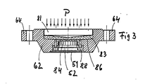
- Figures 2 to 4 show further embodiments of a pressure measuring cell according to the invention, in which the pressure sensor is not completely embedded, but is only in contact with the surface with the elastomeric material 43.
- Such an arrangement preferably works, for example, with a ceramic pressure sensor that responds to mechanical bending stresses.
- FIGS. 2 to 4 differ only in the arrangement of the piston 41, the description of the embodiment of FIG. 2 should suffice, whereby this also relates to the deviations according to FIG. 1.
- the recess 86 is provided on its bottom with a central opening 82, the diameter of which is preferably slightly smaller than the diameter of the ceramic pressure sensor 84, which is embedded in the bottom of the housing 62.
- the pressure sensor 84 is fixed, for example, by means of a ring 88 in the bottom of the housing 62.
- the housing is to be fastened to the desired position via flanges 64 provided with bores.
- the piston 81 can either be embedded in the elastomeric material 83 (FIG. 2), close off the elastomeric material (FIG. 3) or not be present at all (FIG. 4).
- the elastomeric material 43 or 83 is bubble-free.
- a method is therefore used to produce the pressure measuring cell according to the invention, as is known from DE-OS 34 44 996 and how it is applied, for example, to force measuring cells, as described in the international patent application PCT / EP 8500691 (WO 86/03584) .
- the content of these documents is made entirely the content of the present patent application.
- pressure sensors can be used for the pressure measuring cell according to the invention, such as thick-film ceramic membranes, GaAs Hall generators, piezoelectric and piezo-resistive membranes etc.
- the pressure measuring cell according to the invention is particularly suitable for the relatively exact determination of the pressure in liquids and gases in a pressure range between 2 and 400 bar.
Landscapes
- Physics & Mathematics (AREA)
- General Physics & Mathematics (AREA)
- Chemical & Material Sciences (AREA)
- Analytical Chemistry (AREA)
- Measuring Fluid Pressure (AREA)
Applications Claiming Priority (2)
| Application Number | Priority Date | Filing Date | Title |
|---|---|---|---|
| DE3625842 | 1986-07-30 | ||
| DE19863625842 DE3625842A1 (de) | 1986-07-30 | 1986-07-30 | Druckmesszelle |
Publications (2)
| Publication Number | Publication Date |
|---|---|
| EP0255084A2 true EP0255084A2 (fr) | 1988-02-03 |
| EP0255084A3 EP0255084A3 (fr) | 1990-02-21 |
Family
ID=6306350
Family Applications (1)
| Application Number | Title | Priority Date | Filing Date |
|---|---|---|---|
| EP87110857A Withdrawn EP0255084A3 (fr) | 1986-07-30 | 1987-07-27 | Capteur de pression |
Country Status (2)
| Country | Link |
|---|---|
| EP (1) | EP0255084A3 (fr) |
| DE (1) | DE3625842A1 (fr) |
Cited By (2)
| Publication number | Priority date | Publication date | Assignee | Title |
|---|---|---|---|---|
| US5144841A (en) * | 1990-02-23 | 1992-09-08 | Texas Instruments Incorporated | Device for measuring pressures and forces |
| WO1998055355A1 (fr) * | 1997-06-04 | 1998-12-10 | Continental Emsco Company | Systeme de mesure de charges et de flexions pour paliers elastomeres |
Families Citing this family (13)
| Publication number | Priority date | Publication date | Assignee | Title |
|---|---|---|---|---|
| DE4003048A1 (de) * | 1990-02-02 | 1991-08-08 | Pfister Gmbh | Messzelle |
| DE4102931A1 (de) * | 1991-01-31 | 1992-08-13 | Pfister Messtechnik | Kraftmessvorrichtung und verfahren zu deren herstellung |
| DE4234290C2 (de) * | 1992-10-12 | 1995-06-14 | Fibronix Sensoren Gmbh | Drucksensor |
| DE4307306C2 (de) * | 1993-03-09 | 1995-11-02 | Wilo Gmbh | Meßanschlußstelle |
| FR2713764B1 (fr) † | 1993-11-10 | 1996-01-12 | Ksb Sa | Dispositif de mesure d'un fluide. |
| DE19718349C2 (de) * | 1997-05-02 | 2001-03-01 | Mahe Electronic Mario Mankel | Drucksensor |
| DE19753874A1 (de) * | 1997-12-05 | 1999-06-17 | Bosch Gmbh Robert | Kraftsensor |
| DE19806058A1 (de) * | 1998-02-13 | 1999-09-09 | Fraunhofer Ges Forschung | Meßeinrichtung zum Messen von Kraft oder Druck und Verfahren zur Herstellung einer Meßeinrichtung |
| DE10043754B4 (de) * | 2000-09-05 | 2009-08-06 | First Sensor Technology Gmbh | Hochdrucksensor |
| DE20216822U1 (de) * | 2002-10-31 | 2003-08-14 | Keller AG für Druckmeßtechnik, Winterthur | Druck-Transducer |
| DE102007042976B4 (de) * | 2007-09-10 | 2012-12-13 | Continental Automotive Gmbh | Drucksensor und Verfahren zu dessen Herstellung |
| DE102013021025A1 (de) * | 2013-12-17 | 2015-06-18 | Wika Alexander Wiegand Se & Co. Kg | Druckmessgerät mit Vorlagentrennung |
| DE102020206027B4 (de) | 2020-05-13 | 2024-10-02 | Festo Se & Co. Kg | Drucksensoreinrichtung und damit ausgestattete Fluidführungseinrichtung |
Family Cites Families (11)
| Publication number | Priority date | Publication date | Assignee | Title |
|---|---|---|---|---|
| US1994388A (en) * | 1930-07-18 | 1935-03-12 | Erichsen Abraham Martinius | Apparatus for measuring and indicating forces |
| US3269174A (en) * | 1964-03-09 | 1966-08-30 | Frank A Linville | Stress sensor and stress sensing system |
| FR1438366A (fr) * | 1965-03-22 | 1966-05-13 | B A R A | Appareil de mesure de force ou pression |
| US4127788A (en) * | 1977-07-08 | 1978-11-28 | Daugherty Ralph N | Piezoelectric stress indicator for mine roofs |
| DE2755211A1 (de) * | 1977-12-10 | 1979-06-13 | Philips Patentverwaltung | Anordnung zur direkten messung hydrostatischer druecke |
| US4175429A (en) * | 1978-03-13 | 1979-11-27 | Betriesbsforschungsinstitut VDEh Institut fur angewandte Forschung GmbH | Device for the measurement of forces or pressures |
| JPS58146827A (ja) * | 1982-02-25 | 1983-09-01 | Fuji Electric Co Ltd | 半導体式圧力センサ |
| DE3344901A1 (de) * | 1983-12-12 | 1985-06-13 | Pfister Gmbh, 8900 Augsburg | Kraftmesszelle |
| DE3444996A1 (de) * | 1984-12-10 | 1986-06-12 | Pfister Gmbh, 8900 Augsburg | Verfahren und vorrichtung zum blasenfreien aushaerten von polymeren kunststoffen |
| DE3500613A1 (de) * | 1984-03-09 | 1985-09-19 | Hans W. Dipl.-Phys. ETH Winterthur Keller | Piezoresistive druckmesszelle |
| DD234559A3 (de) * | 1984-09-03 | 1986-04-09 | Messgeraetewerk Zwonitz Veb K | Druckmesswandler |
-
1986
- 1986-07-30 DE DE19863625842 patent/DE3625842A1/de active Granted
-
1987
- 1987-07-27 EP EP87110857A patent/EP0255084A3/fr not_active Withdrawn
Cited By (3)
| Publication number | Priority date | Publication date | Assignee | Title |
|---|---|---|---|---|
| US5144841A (en) * | 1990-02-23 | 1992-09-08 | Texas Instruments Incorporated | Device for measuring pressures and forces |
| WO1998055355A1 (fr) * | 1997-06-04 | 1998-12-10 | Continental Emsco Company | Systeme de mesure de charges et de flexions pour paliers elastomeres |
| US5905212A (en) * | 1997-06-04 | 1999-05-18 | Continental Emsco Company | Load and deflection measurement system for elastomeric bearings |
Also Published As
| Publication number | Publication date |
|---|---|
| DE3625842C2 (fr) | 1988-10-20 |
| EP0255084A3 (fr) | 1990-02-21 |
| DE3625842A1 (de) | 1988-02-04 |
Similar Documents
| Publication | Publication Date | Title |
|---|---|---|
| DE3625842C2 (fr) | ||
| DE2237535C2 (de) | Druckwandler | |
| DE3631647C2 (de) | Anordnung zur Aufnahme von Biegungen und Deformationen in einem mechanischem Teil oder einer Struktur | |
| EP1169202B1 (fr) | Dispositif pour mesurer une pression de fluide | |
| EP0499202A2 (fr) | Dispositif pour déterminer la distribution de pression dans un trajet limité et procédé pour sa fabrication | |
| EP3220116B1 (fr) | Dispositif de capteur de force | |
| CH658720A5 (de) | Messsonde fuer lagerbehaelter. | |
| EP0205044B1 (fr) | Systèmes de mesure d'extension en céramique résistant à de hautes températures | |
| DE3020785A1 (de) | Messwandler | |
| EP0568068A2 (fr) | Dispositif de mesure de force | |
| AT507198B1 (de) | Kraftmessring mit einem ringförmigen gehäuse | |
| EP0191305B1 (fr) | Dispositif pour mesurer la charge d'essieu de véhicules | |
| DE2904844C3 (de) | Druckmeßeinrichtung zur Messung und Überwachung von Betonspannungen | |
| WO2004065799A2 (fr) | Systeme de fixation pour un appareil de mesure destine a surveiller et/ou determiner un niveau | |
| DE102023205726A1 (de) | Kabeldurchführung | |
| EP2091596B1 (fr) | Dispositif et procédé de contrôle et de surveillance de la pression dans des conduites de pression ou des tuyaux | |
| EP1525462B1 (fr) | Procede pour produire des sondes ph | |
| EP0472201A2 (fr) | Capteur de pression | |
| DE2263901B2 (de) | Meßumformer | |
| EP2213992A1 (fr) | Dispositif de détermination du poids de la teneur en silo d'un silo | |
| DE102014009847B4 (de) | Wägezelle mit hydraulischer Zentriervorrichtung | |
| EP0288588A1 (fr) | Capteur de courant | |
| CH674579A5 (en) | Pressure and force measuring device - has plate supporting pressure transducer with spaced stop shoulder for overload protection | |
| EP0868658A1 (fr) | Dispositif de mesure de force | |
| DE4110389A1 (de) | Kraftmessvorrichtung |
Legal Events
| Date | Code | Title | Description |
|---|---|---|---|
| PUAI | Public reference made under article 153(3) epc to a published international application that has entered the european phase |
Free format text: ORIGINAL CODE: 0009012 |
|
| AK | Designated contracting states |
Kind code of ref document: A2 Designated state(s): AT BE CH FR GB IT LI |
|
| PUAL | Search report despatched |
Free format text: ORIGINAL CODE: 0009013 |
|
| AK | Designated contracting states |
Kind code of ref document: A3 Designated state(s): AT BE CH FR GB IT LI |
|
| 17P | Request for examination filed |
Effective date: 19900130 |
|
| 17Q | First examination report despatched |
Effective date: 19910326 |
|
| STAA | Information on the status of an ep patent application or granted ep patent |
Free format text: STATUS: THE APPLICATION IS DEEMED TO BE WITHDRAWN |
|
| 18D | Application deemed to be withdrawn |
Effective date: 19930608 |
|
| RIN1 | Information on inventor provided before grant (corrected) |
Inventor name: HAEFNER, HANS W. |