EP0255095A2 - Antenne pour transpondeur - Google Patents
Antenne pour transpondeur Download PDFInfo
- Publication number
- EP0255095A2 EP0255095A2 EP87110869A EP87110869A EP0255095A2 EP 0255095 A2 EP0255095 A2 EP 0255095A2 EP 87110869 A EP87110869 A EP 87110869A EP 87110869 A EP87110869 A EP 87110869A EP 0255095 A2 EP0255095 A2 EP 0255095A2
- Authority
- EP
- European Patent Office
- Prior art keywords
- conductive material
- antenna
- slots
- antenna assembly
- set forth
- Prior art date
- Legal status (The legal status is an assumption and is not a legal conclusion. Google has not performed a legal analysis and makes no representation as to the accuracy of the status listed.)
- Granted
Links
Images
Classifications
-
- H—ELECTRICITY
- H01—ELECTRIC ELEMENTS
- H01Q—ANTENNAS, i.e. RADIO AERIALS
- H01Q13/00—Waveguide horns or mouths; Slot antennas; Leaky-waveguide antennas; Equivalent structures causing radiation along the transmission path of a guided wave
- H01Q13/10—Resonant slot antennas
- H01Q13/106—Microstrip slot antennas
-
- H—ELECTRICITY
- H01—ELECTRIC ELEMENTS
- H01Q—ANTENNAS, i.e. RADIO AERIALS
- H01Q5/00—Arrangements for simultaneous operation of antennas on two or more different wavebands, e.g. dual-band or multi-band arrangements
- H01Q5/30—Arrangements for providing operation on different wavebands
- H01Q5/307—Individual or coupled radiating elements, each element being fed in an unspecified way
- H01Q5/342—Individual or coupled radiating elements, each element being fed in an unspecified way for different propagation modes
- H01Q5/357—Individual or coupled radiating elements, each element being fed in an unspecified way for different propagation modes using a single feed point
-
- H—ELECTRICITY
- H01—ELECTRIC ELEMENTS
- H01Q—ANTENNAS, i.e. RADIO AERIALS
- H01Q9/00—Electrically-short antennas having dimensions not more than twice the operating wavelength and consisting of conductive active radiating elements
- H01Q9/04—Resonant antennas
- H01Q9/06—Details
- H01Q9/065—Microstrip dipole antennas
Definitions
- This invention relates to antennas and more particularly relates to antennas operative at two (2) widely separated frequencies.
- the antenna of this invention is particularly adapted to be used in a transponder which constitutes a tag attached to an object to identify the object by transmitting to a reader signals identifying the object.
- Systems have been developed for identifying an object on a remote basis. Such systems include a reader displaced from the object for interrogating a transponder at the object.
- the trnaponder has an identifying code which is individual to the object being interrogated. This code is represented by a sequence of binary 1's and binary 0's in a pattern individual to the object. Each of the binary 1's and binary 0's in this sequence is converted to a plurality of signals which are transmitted to the reader.
- the signals in each plurality may have first and second frequencies in a particular pattern to identify a binary "1" and may have first and second frequencies in another pattern to identify a binary "0".
- the transponder has an antenna (or antennas) for transmitting the identifying signals to the reader.
- the transmitting frequency adopted by Government regulations in the United States, Europe and Hong Kong has been approximately nine hundred and fifteen megaherts (915 MHz).
- the transmitting frequency adopted by Government regulations in the Far East (except for Hong Kong) has been approximately twenty four hundred and fifty megahertz (2450 MHz).
- This invention provides a transmitter assembly which is useful in a transponder to receive and transmit signals at a first frequency such as approximately nine hundred and fifteen megahertz (915 MHz) and at a second frequency such as approximately twenty four hundred and fifty megahertz (2450 MHz).
- the transmitter assembly includes a single antenna assembly defining two (2) antennas each disposed on a single dielectric member and each operative at an individual one of the frequencies. Each of the antennas is effective in receiving and transmitting signals at its individual frequency.
- a dielectric member may be thin and planar and may have first and second opposite surfaces.
- An electrically conductive material is disposed on the first surface at one end of the first surface and an electrically conductive material is disposed on the second surface at the opposite end of the second surface.
- the conductive materials in the first and second surfaces define a first antenna operative at a first frequency such as nine hundred and fifteen megahertz (915 MHz).
- the slots are provided in the conductive material in the first surface.
- the slots define a second antenna operative at a second frequency greater than the first frequency. This second frequency may be twenty four hundred and fifty megahertz (2450 MHz).
- the slots include first and second slots extending in a direction transverse to the relative direction of the conductive materials on the first and second surfaces.
- the first and second slots may have substantially equal lengths and may be aligned with each other.
- the slots are include third and fourth slots extending in such relative direction.
- the lengths of the first and second slots define the frequency of the signals from the second antenna and the lengths of the third and fourth slots define the impedance of the second antenna.
- the third and fourth slots are disposed in a spaced and parallel relationship to define a conductive portion.
- Additional conductive material is disposed on the first surface of the dielectric member in electrical communication with the conductive portion on the first surface.
- the additional conductive material is disposed opposite the conductive material on the second surface and is provided with a length defining the impedance of the first antenna.
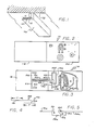
- an antenna assembly generally indicated at 10 includes a dielectric member 12.
- the dielectric member 12 may be made from a suitable material such as fiberglass and may be provided with a relatively small thickness such as in the order of one sixteenth of an inch (1/16").
- the dielectric member may be provided with oppositely disposed parallel surfaces 14 and 16.
- the dielectric member 12 may have a suitable length such as approximately six and one half inches (6 1/2") and a suitable width such as approximately two inches (2").
- a conductive material 18 may be disposed on the first surface 14 of the dielectric member 12.
- the conductive material 18 may be made from a thin sheet of a suitable material such as copper and this thin sheet may be covered with a suitable material such as a nickel solder.
- the conductive material 18 may cover approximately one half (1/2) of the area of the first surface 14.
- a conductive material 20 may cover approximately one half (1/2) of the area of the second surface 16.
- each of the conductive materials 18 and 20 may have a suitable length such as approximately three and one quarter inches (3 1/4") and a suitable width such as approximately two inches (2").
- the conductive material 20 is at the opposite end of the dielectric member 12 from the dielectric member 18.
- the conductive materials 18 and 20 define a dipole antenna generally indicated at 22 in Figure 4. This dipole antenna preferably has a suitable frequency such as in the order of nine hundred and fifteen megahertz (915 MHz).
- Slots 26 are provided in the conductive material 18.
- the slots 26 extend in a direction transverse to the relative direction of the conductive materials 18 and 20.
- Each of the slots 26 may have a suitable length such as approximately three quarters of an inch (3/4") and a suitable width such as approximately three thirty seconds of an inch (3/32").
- the slots 26 are substantially aligned with each other.
- the slots 26 are separated from each other by a conductive portion 28 having a suitable width such as approximately one sixteenth of an inch (“1/16").
- each of the slots 26 has an extension 30 which extends in the relative direction of the conductive materials 18 and 20.
- Each of the slot extensions 30 may have a suitable length such as approximately one half of an inch (1/2") and a suitable width such as approximately three thirty seconds an inch (3/32").
- the slots 26 and the extensions 30 define a second antenna having a suitable frequency such as approximately twenty four hundred and fifty megahertz (2450 MHz).
- the conductive portion 28 extends for a suitable distance such as approximately one and five eighth inches (1 5/8") in the relative direction of the conductive materials 18 and 20 and has a width of approximately three sixteenths of an inch (3/16").
- the end of the conductive portion 28 coincides substantially with the end of the conductive material 18 on the surface 14.
- the conductive portion 28 is defined by slots 32 each having a length of approxiamtely one and one half inches (1 1/2") and a width of approximately one eight of an inch (1/8").
- the dimensions of the conductive portion 28 define the impedance of the second antenna.
- Additional conductive material generally indicated at 36 extends from the conductive portion 28 along the first surface 14 of the dielectric member 12.
- the additional conductive material 36 is disposed on the half of the first surface 14 where none of the conductive material 18 is disposed. As a result, the additional conductive material 36 is disposed directly opposite the conductive material 20 on the second surface 16.
- the additional conductive material 36 preferably has a looped configuration defined by portions 40, 42, 44, 46, 48 and 50. These portions have widths of approximately one eighth of an inch (1/8") and respectively have lengths of approximately three eights of an inch (1/8"), three quarters of an inch (3/4"), three eights of an inch (3/8"), one inch (1"), three eights of an inch (3/8") and one quarter of an inch (1/4").
- the dimensions of the portions 40, 42, 44, 46, 48 and 50 define the impedance of the first antenna formed by the conductive materials 18 and 20.
- Figure 4 illustrates on a schematic basis the dipole formed by the conductive materials 18 and 20.
- the additional conductive material 36 is shown as extending on the first surface 18 over a portion of the conductive material 20 on the second surface 20.
- Figure 5 illustrates an equivalent arrangement which would be formed if the conductive materials 18 and 20 were in the same plane, as illustrated at 18a and 20a. Under such circumstances, the additional conductive material 36 would be in a different plane as indicated at 36a. The current flow would then be in a direction as indicated by arrows 50, 52 and 54 in Figure 5.
- a load 60 would then be considered as being connected between the conductive material 20a and the additional conductive material 36a.
- the formation of the slots 26 in the conductive material 18 tends to limit the magnitudes of the currents provided in the dipole antenna which is defined by the conductive materials 18 and 20.
- the antenna defined by the conductive materials 18 and 20 is able to provide a relatively large magnitude of current. This limitation in current is offset, however, by the advantage of having a second antenna on the dielectric member 12.
- the provision of two antennas in the antenna assembly 10 is advantageous because different frequencies are used in transponders throughout the world.
- a frequency of approximately nine hundred and fifteen megahertz (915 MHz) is used in the United States, Europe and Hong Kong.
- a frequency of twenty four hundred and fifty megahertz (2450 MHz) is used in the Far East except for Hong Kong.
- the antenna assembly 10 can accordingly be used throughout the world.
- the antenna defined by the conductive portions 18 and 20 provides high voltages at the centers of the surfaces 14 and 16. The voltage in this antenna decreases toward the periphery of the conductive materials 18 and 20 in the lengthwise direction. Similarly, the antenna at the high frequency provides a high voltage at the center positions of the slots 26 and provides a decreasing voltage towards the periphery of the slots.
- the antenna assembly 10 may be included in a transponder generally indicated at 70 in Figure 1.
- the transponder 70 may be constructed as disclosed fully and claimed in co-pending application Serial No. filed on July 14, 1986, in the name of Alfred R. Koelle and assigned of record to the assignee of record of this application.
- the transponder 70 may be attached to an object 72 to transmit to a reader (not shown) pluralities of signal cycles in an individual code identifying the object. This code may be identified by individual combinations of signal cycles at first and second frequencies such as twenty kilohertz (20 KHz) and forty kilohertz (40 KHz).
- the reader may be constructed as disclosed fully and claimed in co-pending application Serial No. filed on July 14, 1986, in the names of Alfred R. Koelle and Jeremy A. Landt as joint inventors and assigned of record to the assignee of record of this application.
Landscapes
- Details Of Aerials (AREA)
- Waveguide Aerials (AREA)
- Radar Systems Or Details Thereof (AREA)
- Near-Field Transmission Systems (AREA)
Applications Claiming Priority (2)
| Application Number | Priority Date | Filing Date | Title |
|---|---|---|---|
| US891226 | 1986-07-29 | ||
| US06/891,226 US4782345A (en) | 1986-07-29 | 1986-07-29 | Transponder antenna |
Publications (3)
| Publication Number | Publication Date |
|---|---|
| EP0255095A2 true EP0255095A2 (fr) | 1988-02-03 |
| EP0255095A3 EP0255095A3 (en) | 1989-11-29 |
| EP0255095B1 EP0255095B1 (fr) | 1995-01-18 |
Family
ID=25397815
Family Applications (1)
| Application Number | Title | Priority Date | Filing Date |
|---|---|---|---|
| EP87110869A Expired - Lifetime EP0255095B1 (fr) | 1986-07-29 | 1987-07-27 | Antenne pour transpondeur |
Country Status (10)
| Country | Link |
|---|---|
| US (1) | US4782345A (fr) |
| EP (1) | EP0255095B1 (fr) |
| JP (1) | JP2752620B2 (fr) |
| KR (1) | KR960002828B1 (fr) |
| AU (1) | AU588206B2 (fr) |
| CA (1) | CA1277417C (fr) |
| DE (1) | DE3750997T2 (fr) |
| ES (1) | ES2069526T3 (fr) |
| HK (1) | HK143396A (fr) |
| IL (1) | IL82577A (fr) |
Cited By (8)
| Publication number | Priority date | Publication date | Assignee | Title |
|---|---|---|---|---|
| EP0323011A3 (fr) * | 1987-12-18 | 1989-11-15 | Amtech Technology Corporation | Antenne avec transpondeur |
| EP0331486A3 (fr) * | 1988-03-03 | 1991-05-08 | Shaye Communications Limited | Antenne |
| WO1992001953A1 (fr) * | 1990-07-24 | 1992-02-06 | Saab-Scania Combitech Aktiebolag | Dispositif de transmission d'informations |
| WO1992001952A1 (fr) * | 1990-07-24 | 1992-02-06 | Staffan Gunnarsson | Systeme pour positionner un premier objet par rapport a un deuxieme objet |
| US5392049A (en) * | 1990-07-24 | 1995-02-21 | Gunnarsson; Staffan | Device for positioning a first object relative to a second object |
| DE4437808A1 (de) * | 1994-10-12 | 1996-04-18 | Christian Dr Ing Philipp | Verfahren zur Anbringung und Anordnung einer Identifikationseinrichtung |
| WO2008055526A1 (fr) * | 2006-11-09 | 2008-05-15 | Tes Electronic Solutions Gmbh | Dispositif et système d'antenne et procédé de fonctionnement |
| GB2463711A (en) * | 1987-03-31 | 2010-03-31 | Dassault Electronique | Double polarization flat antenna array |
Families Citing this family (67)
| Publication number | Priority date | Publication date | Assignee | Title |
|---|---|---|---|---|
| US5355126A (en) * | 1990-08-06 | 1994-10-11 | Motorola, Inc. | Selective call system interactive with a wide area selective call system |
| US5270724A (en) * | 1991-04-04 | 1993-12-14 | Hughes Aircraft Company | Multifrequency phased array aperture |
| US5172121A (en) * | 1991-04-30 | 1992-12-15 | Consolidated Rail Corp. | System for automatic identification of rail cars |
| US5343906A (en) * | 1992-05-15 | 1994-09-06 | Biodigital Technologies, Inc. | Emisson validation system |
| US5491482A (en) * | 1992-12-29 | 1996-02-13 | David Sarnoff Research Center, Inc. | Electronic system and method for remote identification of coded articles and the like |
| US5414624A (en) * | 1993-11-08 | 1995-05-09 | Avid Systems Corporation | Automated vehicle parking system |
| US5525993A (en) * | 1995-05-12 | 1996-06-11 | The Regents Of The University Of California | Microwave noncontact identification transponder using subharmonic interrogation and method of using the same |
| US7511621B1 (en) | 1995-08-31 | 2009-03-31 | Intermec Ip Corp. | High-performance mobile power antennas |
| US5737710A (en) | 1995-11-07 | 1998-04-07 | Amtech Corporation | Automated vehicle parking system for a plurality of remote parking facilities |
| US6107910A (en) * | 1996-11-29 | 2000-08-22 | X-Cyte, Inc. | Dual mode transmitter/receiver and decoder for RF transponder tags |
| US6049278A (en) * | 1997-03-24 | 2000-04-11 | Northrop Grumman Corporation | Monitor tag with patch antenna |
| US6060815A (en) | 1997-08-18 | 2000-05-09 | X-Cyte, Inc. | Frequency mixing passive transponder |
| US6208062B1 (en) | 1997-08-18 | 2001-03-27 | X-Cyte, Inc. | Surface acoustic wave transponder configuration |
| US6114971A (en) * | 1997-08-18 | 2000-09-05 | X-Cyte, Inc. | Frequency hopping spread spectrum passive acoustic wave identification device |
| US5986382A (en) | 1997-08-18 | 1999-11-16 | X-Cyte, Inc. | Surface acoustic wave transponder configuration |
| US6281794B1 (en) | 1998-01-02 | 2001-08-28 | Intermec Ip Corp. | Radio frequency transponder with improved read distance |
| US6177872B1 (en) | 1998-03-13 | 2001-01-23 | Intermec Ip Corp. | Distributed impedance matching circuit for high reflection coefficient load |
| US6249227B1 (en) | 1998-01-05 | 2001-06-19 | Intermec Ip Corp. | RFID integrated in electronic assets |
| US6104291A (en) * | 1998-01-09 | 2000-08-15 | Intermec Ip Corp. | Method and apparatus for testing RFID tags |
| US6441740B1 (en) | 1998-02-27 | 2002-08-27 | Intermec Ip Corp. | Radio frequency identification transponder having a reflector |
| US6639509B1 (en) | 1998-03-16 | 2003-10-28 | Intermec Ip Corp. | System and method for communicating with an RFID transponder with reduced noise and interference |
| US6121878A (en) * | 1998-05-01 | 2000-09-19 | Intermec Ip Corp. | System for controlling assets |
| PL196801B1 (pl) * | 1998-09-23 | 2008-01-31 | Georg Utz Holding Ag | Urządzenie transportowe z tworzywa sztucznego mające środki identyfikujące |
| US6201474B1 (en) | 1998-10-21 | 2001-03-13 | Intermec Ip Corp. | Magnetic tape storage media having RFID transponders |
| US6100804A (en) * | 1998-10-29 | 2000-08-08 | Intecmec Ip Corp. | Radio frequency identification system |
| US6366260B1 (en) | 1998-11-02 | 2002-04-02 | Intermec Ip Corp. | RFID tag employing hollowed monopole antenna |
| US6236223B1 (en) | 1998-11-09 | 2001-05-22 | Intermec Ip Corp. | Method and apparatus for wireless radio frequency testing of RFID integrated circuits |
| US6121880A (en) | 1999-05-27 | 2000-09-19 | Intermec Ip Corp. | Sticker transponder for use on glass surface |
| US6608551B1 (en) | 1999-09-13 | 2003-08-19 | Intermec Ip Corp | Low-cost radio replacement utilizing RFID technology |
| US6628237B1 (en) | 2000-03-25 | 2003-09-30 | Marconi Communications Inc. | Remote communication using slot antenna |
| US6535175B2 (en) | 2000-06-01 | 2003-03-18 | Intermec Ip Corp. | Adjustable length antenna system for RF transponders |
| US6894624B2 (en) * | 2000-07-04 | 2005-05-17 | Credipass Co., Ltd. | Passive transponder identification and credit-card type transponder |
| KR100409047B1 (ko) * | 2001-03-23 | 2003-12-11 | (주)크레디패스 | 장거리 인식을 위한 원격 인식 시스템을 내장한 신용카드형 트랜스폰더 |
| US6637703B2 (en) * | 2000-12-28 | 2003-10-28 | Ge Harris Railway Electronics Llc | Yard tracking system |
| US20020130817A1 (en) * | 2001-03-16 | 2002-09-19 | Forster Ian J. | Communicating with stackable objects using an antenna array |
| US6825766B2 (en) | 2001-12-21 | 2004-11-30 | Genei Industries, Inc. | Industrial data capture system including a choke point portal and tracking software for radio frequency identification of cargo |
| AU2003233113A1 (en) * | 2002-04-24 | 2003-11-10 | Marconi Intellectual Property (Us) Inc | Energy source recharging device and method |
| AU2003233026A1 (en) * | 2002-04-24 | 2003-11-10 | Marconi Intellectual Property (Us) Inc | Rechargeable interrogation reader device and method |
| CA2519425A1 (fr) * | 2002-04-24 | 2003-11-06 | Mineral Lassen Llc | Communication par une source d'energie mettant en oeuvre une antenne a fente |
| DE60322528D1 (de) * | 2002-04-24 | 2008-09-11 | Mineral Lassen Llc | Herstellungsverfahren für eine drahtlose kommunikationseinrichtung und herstellungsvorrichtung |
| US6861993B2 (en) | 2002-11-25 | 2005-03-01 | 3M Innovative Properties Company | Multi-loop antenna for radio-frequency identification |
| US6943749B2 (en) * | 2003-01-31 | 2005-09-13 | M&Fc Holding, Llc | Printed circuit board dipole antenna structure with impedance matching trace |
| US20110205056A9 (en) * | 2003-03-24 | 2011-08-25 | Borovoy Richard D | Adding social networking to devices |
| US7538745B2 (en) * | 2003-03-24 | 2009-05-26 | Ntag Interactive Corporation | Apparatus and method for enhancing face-to-face communication |
| US6956472B1 (en) | 2003-04-28 | 2005-10-18 | Walcott Jr James D | Auto hang tag with radio transponder |
| GB0311361D0 (en) * | 2003-05-19 | 2003-06-25 | Antenova Ltd | Dual band antenna system with diversity |
| US7042413B2 (en) * | 2003-08-22 | 2006-05-09 | Checkpoint Systems, Inc. | Security tag with three dimensional antenna array made from flat stock |
| KR100584328B1 (ko) * | 2003-10-07 | 2006-05-26 | 삼성전자주식회사 | 무선주파수 식별 태그가 결합된 이동 단말 회로 및 그이동 단말기에서의 무선 식별 방법 |
| KR20050040451A (ko) * | 2003-10-28 | 2005-05-03 | 삼성전자주식회사 | 무선주파수 식별 기능을 가지는 이동통신 단말기 및 그이동통신 단말기에서의 무선주파수 식별 프로그래밍 방법 |
| US7049966B2 (en) * | 2003-10-30 | 2006-05-23 | Battelle Memorial Institute Kl-53 | Flat antenna architecture for use in radio frequency monitoring systems |
| KR100566260B1 (ko) * | 2003-11-27 | 2006-03-29 | 삼성전자주식회사 | 무선주파수 식별 태그와 스마트 카드가 결합된 이동단말기및 그 이동단말기에서의 무선 식별 방법 |
| US7417599B2 (en) * | 2004-02-20 | 2008-08-26 | 3M Innovative Properties Company | Multi-loop antenna for radio frequency identification (RFID) communication |
| US7268687B2 (en) | 2004-03-23 | 2007-09-11 | 3M Innovative Properties Company | Radio frequency identification tags with compensating elements |
| US7132946B2 (en) * | 2004-04-08 | 2006-11-07 | 3M Innovative Properties Company | Variable frequency radio frequency identification (RFID) tags |
| US7548153B2 (en) | 2004-07-09 | 2009-06-16 | Tc License Ltd. | Multi-protocol or multi-command RFID system |
| US20060163350A1 (en) * | 2005-01-11 | 2006-07-27 | Melton Michael N | Managing RFID tags using an RFID-enabled cart |
| US7274294B2 (en) * | 2005-01-26 | 2007-09-25 | Rf Technologies, Inc. | Mobile locator system and method |
| US7365645B2 (en) * | 2005-01-26 | 2008-04-29 | Rf Technologies, Inc. | Mobile locator system and method with wander management |
| US20060195354A1 (en) * | 2005-02-28 | 2006-08-31 | Ntag Interactive Corporation | Method of scoring the performance of attendees at a meeting |
| US7501947B2 (en) * | 2005-05-04 | 2009-03-10 | Tc License, Ltd. | RFID tag with small aperture antenna |
| KR100754844B1 (ko) * | 2006-05-24 | 2007-09-04 | 경희대학교 산학협력단 | 알에프 아이디 태그 |
| US7564356B1 (en) | 2006-10-06 | 2009-07-21 | Tc License, Ltd. | Interdigit AC coupling for RFID tags |
| US20130119135A1 (en) * | 2010-07-26 | 2013-05-16 | Polyvalor, Limited Partnership | Bi-directional and multi-frequency rf signaling system |
| US9396367B2 (en) | 2013-02-05 | 2016-07-19 | Amtech Systems, LLC | System and method for synchronizing RFID readers utilizing RF or modulation signals |
| US9355349B2 (en) | 2013-03-07 | 2016-05-31 | Applied Wireless Identifications Group, Inc. | Long range RFID tag |
| US10121289B1 (en) | 2014-04-11 | 2018-11-06 | Amtech Systems, LLC | Vehicle-based electronic toll system with interface to vehicle display |
| US10786797B2 (en) | 2018-09-25 | 2020-09-29 | Uop Llc | Estimation of cyclone life based on remaining abrasion resistant lining thickness |
Family Cites Families (7)
| Publication number | Priority date | Publication date | Assignee | Title |
|---|---|---|---|---|
| US3587110A (en) * | 1969-07-01 | 1971-06-22 | Rca Corp | Corporate-network printed antenna system |
| US3914767A (en) * | 1974-06-11 | 1975-10-21 | Us Army | Monolithic, electrically small, multi-frequency antenna |
| US4130822A (en) * | 1976-06-30 | 1978-12-19 | Motorola, Inc. | Slot antenna |
| US4138684A (en) * | 1977-05-12 | 1979-02-06 | The United States Of America As Represented By The Secretary Of The Army | Loaded microstrip antenna with integral transformer |
| GB2157500B (en) * | 1984-04-11 | 1987-07-01 | Plessey Co Plc | Microwave antenna |
| US4658263A (en) * | 1985-02-11 | 1987-04-14 | Allied Corporation | Dual antenna for magnetic markers |
| SE447428B (sv) * | 1985-03-08 | 1986-11-10 | Luxor Ab | Anordning for att minska interferensstorningar mellan nerliggande detekteringssystem serskilt i samband med sa kallade butikslarmanleggningar |
-
1986
- 1986-07-29 US US06/891,226 patent/US4782345A/en not_active Expired - Lifetime
-
1987
- 1987-05-19 IL IL82577A patent/IL82577A/xx unknown
- 1987-06-16 CA CA000539782A patent/CA1277417C/fr not_active Expired - Lifetime
- 1987-07-20 KR KR1019870007833A patent/KR960002828B1/ko not_active Expired - Fee Related
- 1987-07-27 EP EP87110869A patent/EP0255095B1/fr not_active Expired - Lifetime
- 1987-07-27 DE DE3750997T patent/DE3750997T2/de not_active Expired - Fee Related
- 1987-07-27 ES ES87110869T patent/ES2069526T3/es not_active Expired - Lifetime
- 1987-07-28 JP JP62186807A patent/JP2752620B2/ja not_active Expired - Lifetime
- 1987-07-28 AU AU76185/87A patent/AU588206B2/en not_active Ceased
-
1996
- 1996-08-01 HK HK143396A patent/HK143396A/en not_active IP Right Cessation
Cited By (10)
| Publication number | Priority date | Publication date | Assignee | Title |
|---|---|---|---|---|
| GB2463711A (en) * | 1987-03-31 | 2010-03-31 | Dassault Electronique | Double polarization flat antenna array |
| GB2463711B (en) * | 1987-03-31 | 2010-09-29 | Dassault Electronique | Double polarization flat array antenna |
| EP0323011A3 (fr) * | 1987-12-18 | 1989-11-15 | Amtech Technology Corporation | Antenne avec transpondeur |
| AU603972B2 (en) * | 1987-12-18 | 1990-11-29 | Amtech Systems Corporation | Transponder antenna |
| EP0331486A3 (fr) * | 1988-03-03 | 1991-05-08 | Shaye Communications Limited | Antenne |
| WO1992001953A1 (fr) * | 1990-07-24 | 1992-02-06 | Saab-Scania Combitech Aktiebolag | Dispositif de transmission d'informations |
| WO1992001952A1 (fr) * | 1990-07-24 | 1992-02-06 | Staffan Gunnarsson | Systeme pour positionner un premier objet par rapport a un deuxieme objet |
| US5392049A (en) * | 1990-07-24 | 1995-02-21 | Gunnarsson; Staffan | Device for positioning a first object relative to a second object |
| DE4437808A1 (de) * | 1994-10-12 | 1996-04-18 | Christian Dr Ing Philipp | Verfahren zur Anbringung und Anordnung einer Identifikationseinrichtung |
| WO2008055526A1 (fr) * | 2006-11-09 | 2008-05-15 | Tes Electronic Solutions Gmbh | Dispositif et système d'antenne et procédé de fonctionnement |
Also Published As
| Publication number | Publication date |
|---|---|
| US4782345A (en) | 1988-11-01 |
| EP0255095A3 (en) | 1989-11-29 |
| JP2752620B2 (ja) | 1998-05-18 |
| KR880002287A (ko) | 1988-04-30 |
| DE3750997T2 (de) | 1995-05-18 |
| IL82577A0 (en) | 1987-11-30 |
| JPS6342203A (ja) | 1988-02-23 |
| CA1277417C (fr) | 1990-12-04 |
| EP0255095B1 (fr) | 1995-01-18 |
| ES2069526T3 (es) | 1995-05-16 |
| AU7618587A (en) | 1988-02-04 |
| KR960002828B1 (ko) | 1996-02-26 |
| DE3750997D1 (de) | 1995-03-02 |
| IL82577A (en) | 1991-01-31 |
| HK143396A (en) | 1996-08-09 |
| AU588206B2 (en) | 1989-09-07 |
Similar Documents
| Publication | Publication Date | Title |
|---|---|---|
| US4782345A (en) | Transponder antenna | |
| US6946958B2 (en) | Contactless data storage medium | |
| US5182570A (en) | End fed flat antenna | |
| EP1720216B1 (fr) | Tiquette radio | |
| AU603972B2 (en) | Transponder antenna | |
| US6172608B1 (en) | Enhanced range transponder system | |
| US6215402B1 (en) | Radio frequency identification transponder employing patch antenna | |
| KR101119991B1 (ko) | 향상된 판독 능력을 가지는 고주파 식별 태그 | |
| US5214410A (en) | Location of objects | |
| US20080122628A1 (en) | RFID tag antenna and RFID tag | |
| CN1953273B (zh) | 标签天线、使用该标签天线的标签和射频标识系统 | |
| EP0253877A1 (fr) | Systemes d'antennes. | |
| US20100007567A1 (en) | Antenna for an rfid transponder and rfid transponder | |
| AU2004312803A1 (en) | Ultra high frequency radio frequency identification tag | |
| US7764240B2 (en) | Antenna configuration for RFID tags | |
| FI130267B (en) | UHF RFID tag | |
| US6404406B2 (en) | Antenna having a wide bandwidth | |
| JP2009260447A (ja) | アンテナ及び無線タグ | |
| JP3964645B2 (ja) | 移動体識別装置 | |
| FI20225657A1 (en) | Rfid tag arrangement with omnidirectional antenna characteristics | |
| AU709985B2 (en) | Enhanced range transponder system | |
| CN115117628A (zh) | 一种双频点测温rfid标签天线 | |
| JPH0479550B2 (fr) | ||
| EP0514378A4 (en) | End fed flat antenna |
Legal Events
| Date | Code | Title | Description |
|---|---|---|---|
| PUAI | Public reference made under article 153(3) epc to a published international application that has entered the european phase |
Free format text: ORIGINAL CODE: 0009012 |
|
| AK | Designated contracting states |
Kind code of ref document: A2 Designated state(s): BE CH DE ES FR GB IT LI NL SE |
|
| PUAL | Search report despatched |
Free format text: ORIGINAL CODE: 0009013 |
|
| RHK1 | Main classification (correction) |
Ipc: H01Q 5/00 |
|
| AK | Designated contracting states |
Kind code of ref document: A3 Designated state(s): BE CH DE ES FR GB IT LI NL SE |
|
| 17P | Request for examination filed |
Effective date: 19900528 |
|
| 17Q | First examination report despatched |
Effective date: 19920728 |
|
| GRAA | (expected) grant |
Free format text: ORIGINAL CODE: 0009210 |
|
| AK | Designated contracting states |
Kind code of ref document: B1 Designated state(s): BE CH DE ES FR GB IT LI NL SE |
|
| ITF | It: translation for a ep patent filed | ||
| REF | Corresponds to: |
Ref document number: 3750997 Country of ref document: DE Date of ref document: 19950302 |
|
| ET | Fr: translation filed | ||
| REG | Reference to a national code |
Ref country code: ES Ref legal event code: FG2A Ref document number: 2069526 Country of ref document: ES Kind code of ref document: T3 |
|
| PLBE | No opposition filed within time limit |
Free format text: ORIGINAL CODE: 0009261 |
|
| STAA | Information on the status of an ep patent application or granted ep patent |
Free format text: STATUS: NO OPPOSITION FILED WITHIN TIME LIMIT |
|
| 26N | No opposition filed | ||
| PGFP | Annual fee paid to national office [announced via postgrant information from national office to epo] |
Ref country code: SE Payment date: 19970619 Year of fee payment: 11 |
|
| PGFP | Annual fee paid to national office [announced via postgrant information from national office to epo] |
Ref country code: BE Payment date: 19970626 Year of fee payment: 11 |
|
| PGFP | Annual fee paid to national office [announced via postgrant information from national office to epo] |
Ref country code: ES Payment date: 19970717 Year of fee payment: 11 |
|
| PGFP | Annual fee paid to national office [announced via postgrant information from national office to epo] |
Ref country code: FR Payment date: 19980618 Year of fee payment: 12 |
|
| PGFP | Annual fee paid to national office [announced via postgrant information from national office to epo] |
Ref country code: DE Payment date: 19980625 Year of fee payment: 12 |
|
| PGFP | Annual fee paid to national office [announced via postgrant information from national office to epo] |
Ref country code: GB Payment date: 19980626 Year of fee payment: 12 |
|
| PGFP | Annual fee paid to national office [announced via postgrant information from national office to epo] |
Ref country code: NL Payment date: 19980629 Year of fee payment: 12 |
|
| PGFP | Annual fee paid to national office [announced via postgrant information from national office to epo] |
Ref country code: CH Payment date: 19980706 Year of fee payment: 12 |
|
| PG25 | Lapsed in a contracting state [announced via postgrant information from national office to epo] |
Ref country code: SE Free format text: LAPSE BECAUSE OF NON-PAYMENT OF DUE FEES Effective date: 19980728 Ref country code: ES Free format text: LAPSE BECAUSE OF NON-PAYMENT OF DUE FEES Effective date: 19980728 |
|
| PG25 | Lapsed in a contracting state [announced via postgrant information from national office to epo] |
Ref country code: BE Free format text: LAPSE BECAUSE OF NON-PAYMENT OF DUE FEES Effective date: 19980731 |
|
| BERE | Be: lapsed |
Owner name: AMTECH CORP. Effective date: 19980731 |
|
| EUG | Se: european patent has lapsed |
Ref document number: 87110869.2 |
|
| PG25 | Lapsed in a contracting state [announced via postgrant information from national office to epo] |
Ref country code: GB Free format text: LAPSE BECAUSE OF NON-PAYMENT OF DUE FEES Effective date: 19990727 |
|
| PG25 | Lapsed in a contracting state [announced via postgrant information from national office to epo] |
Ref country code: LI Free format text: LAPSE BECAUSE OF NON-PAYMENT OF DUE FEES Effective date: 19990731 Ref country code: FR Free format text: THE PATENT HAS BEEN ANNULLED BY A DECISION OF A NATIONAL AUTHORITY Effective date: 19990731 Ref country code: CH Free format text: LAPSE BECAUSE OF NON-PAYMENT OF DUE FEES Effective date: 19990731 |
|
| PG25 | Lapsed in a contracting state [announced via postgrant information from national office to epo] |
Ref country code: NL Free format text: LAPSE BECAUSE OF NON-PAYMENT OF DUE FEES Effective date: 20000201 |
|
| GBPC | Gb: european patent ceased through non-payment of renewal fee |
Effective date: 19990727 |
|
| REG | Reference to a national code |
Ref country code: CH Ref legal event code: PL |
|
| NLV4 | Nl: lapsed or anulled due to non-payment of the annual fee |
Effective date: 20000201 |
|
| PG25 | Lapsed in a contracting state [announced via postgrant information from national office to epo] |
Ref country code: DE Free format text: LAPSE BECAUSE OF NON-PAYMENT OF DUE FEES Effective date: 20000503 |
|
| REG | Reference to a national code |
Ref country code: FR Ref legal event code: ST |
|
| REG | Reference to a national code |
Ref country code: ES Ref legal event code: FD2A Effective date: 19990811 |
|
| PG25 | Lapsed in a contracting state [announced via postgrant information from national office to epo] |
Ref country code: IT Free format text: LAPSE BECAUSE OF NON-PAYMENT OF DUE FEES;WARNING: LAPSES OF ITALIAN PATENTS WITH EFFECTIVE DATE BEFORE 2007 MAY HAVE OCCURRED AT ANY TIME BEFORE 2007. THE CORRECT EFFECTIVE DATE MAY BE DIFFERENT FROM THE ONE RECORDED. Effective date: 20050727 |