EP0255183A1 - Bodenbearbeitungsmaschine - Google Patents
Bodenbearbeitungsmaschine Download PDFInfo
- Publication number
- EP0255183A1 EP0255183A1 EP87201444A EP87201444A EP0255183A1 EP 0255183 A1 EP0255183 A1 EP 0255183A1 EP 87201444 A EP87201444 A EP 87201444A EP 87201444 A EP87201444 A EP 87201444A EP 0255183 A1 EP0255183 A1 EP 0255183A1
- Authority
- EP
- European Patent Office
- Prior art keywords
- trestle
- machine
- coupling
- soil cultivating
- cultivating machine
- Prior art date
- Legal status (The legal status is an assumption and is not a legal conclusion. Google has not performed a legal analysis and makes no representation as to the accuracy of the status listed.)
- Withdrawn
Links
- 239000002689 soil Substances 0.000 title claims abstract description 33
- 230000008878 coupling Effects 0.000 claims abstract description 35
- 238000010168 coupling process Methods 0.000 claims abstract description 35
- 238000005859 coupling reaction Methods 0.000 claims abstract description 35
- 238000010276 construction Methods 0.000 description 2
- 230000005540 biological transmission Effects 0.000 description 1
- 230000000694 effects Effects 0.000 description 1
- 238000002360 preparation method Methods 0.000 description 1
- 238000009331 sowing Methods 0.000 description 1
- 230000006641 stabilisation Effects 0.000 description 1
Images

Classifications
-
- A—HUMAN NECESSITIES
- A01—AGRICULTURE; FORESTRY; ANIMAL HUSBANDRY; HUNTING; TRAPPING; FISHING
- A01B—SOIL WORKING IN AGRICULTURE OR FORESTRY; PARTS, DETAILS, OR ACCESSORIES OF AGRICULTURAL MACHINES OR IMPLEMENTS, IN GENERAL
- A01B59/00—Devices specially adapted for connection between animals or tractors and agricultural machines or implements
- A01B59/06—Devices specially adapted for connection between animals or tractors and agricultural machines or implements for machines mounted on tractors
- A01B59/061—Devices specially adapted for connection between animals or tractors and agricultural machines or implements for machines mounted on tractors specially adapted for enabling connection or disconnection controlled from the driver's seat
- A01B59/062—Devices specially adapted for connection between animals or tractors and agricultural machines or implements for machines mounted on tractors specially adapted for enabling connection or disconnection controlled from the driver's seat the connection comprising a rigid interface frame on the tractor
-
- A—HUMAN NECESSITIES
- A01—AGRICULTURE; FORESTRY; ANIMAL HUSBANDRY; HUNTING; TRAPPING; FISHING
- A01B—SOIL WORKING IN AGRICULTURE OR FORESTRY; PARTS, DETAILS, OR ACCESSORIES OF AGRICULTURAL MACHINES OR IMPLEMENTS, IN GENERAL
- A01B49/00—Combined machines
- A01B49/04—Combinations of soil-working tools with non-soil-working tools, e.g. planting tools
- A01B49/06—Combinations of soil-working tools with non-soil-working tools, e.g. planting tools for sowing or fertilising
- A01B49/065—Combinations of soil-working tools with non-soil-working tools, e.g. planting tools for sowing or fertilising the soil-working tools being actively driven
Definitions
- the invention concerns a soil cultivating machine comprising a frame provided with a trestle for coupling to the lifting hitch of a tractor and a plurality of power-driven soil working members arranged in a row extending transversely to the direction of operative travel, coupling means being arranged at the rear side of the machine for coupling an implement to be combined with the machine, which coupling means includes a trestle whose downwardly directed legs are connected pivotally at the lower side to pivotally arranged arms.
- pivotal connection includes a support for the downwardly directed legs of the trestle, which support has two spaced-apart, adjacent supporting points.
- a further feature of the invention concerns a construction in which, as seen in plan view, the trestle forming part of the coupling means is located in the region of the rear side of a frame portion supporting the soil working members.
- the implement to be combined with the machine can be positioned as closely as possible thereto, thus enabling the whole to be arranged as closely as possible to the rear of the tractor, as a result of which, in particular during transportation, unwanted loading of the lifting hitch of the tractor is prevented.
- the implement shown in the drawings concerns a soil cultivating machine, in particular one for the preparation of a seed bed.
- the machine comprises a box-like frame portion 1 which extends transversely to the direction of operative travel A and in which are supported, spaced apart equidistantly by preferably 25 cms, the upwardly, preferably vertically, extending shafts 2 of soil working members 3.
- Each of the soil working members 3 includes a carrier 4 which extends at least substantially horizontally and is mounted on the end of a shaft 2 that projects from the bottom of the frame portion 1.
- each carrier 4 is provided with soil working elements 5 which extend downwardly and are afforded by tines.
- the ends of the box-like frame portion 1 are closed by means of plates 6 which extend at least substantially parallel to the direction of operative travel A.
- Each of the plates 6 has at its front side a bolt 7 which extends transversely to the direction of operative travel A and about which is pivotal an arm 8 extending rearwardly along the inner side of the plates. Between the free ends of the arms 8 there is arranged freely rotatably a roller 9.
- Each of the arms 8 can be adjusted in height by means of an adjusting device, in this case formed by a threaded spindle 10, and be locked in a plurality of positions, the arrangement being such that the working depth of the soil working members 3 can be set by means of the roller.
- each shaft 2 of a soil working member 3 is provided with a pinion 11, the arrangement being such that the pinions on the shafts of adjacent soil working members are in driving connection with each other.
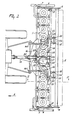
- the shaft 2 of a soil working member 3 located near the centre of the box-like frame portion is extended upwardly and by means of this extension reaches to into a gear box 12, inside which the extension is in driving connection via a speed variator 13 with a shaft 14 which extends in the direction of operative travel A, projects at the front side from said gear box, and can be coupled to the power take-off shaft of a tractor via an intermediate shaft 15.
- the front side of the box-like frame portion 1 includes a trestle 16 which has a three-point connection for coupling to the three-point lifting hitch of a tractor.
- the trestle 16 is disposed on the upper side of the box-like frame portion 1 and at its rear side is provided with coupling means 17 for coupling an implement, such as a seed drill or a planter, to be combined with the machine.
- the coupling means 17 comprise two arms 18 which are connected pivotally near the front side of the frame portion 1 to the middle of the plates 16A by means of a shaft 19 extending transversely to the direction of operative travel A. From the shaft 19, each of the arms 18 extends rearwardly along the outer side of a plate 16A.
- Each of the arms 18 is provided in the region of the rear side of the frame portion 1 with a hook 20 which, together with the arm, constitutes a bracket 21 whose legs, seen in plan view, at least reach to the front side of the roller.
- a support 22 Between the hook 20 and a point located before the connection of the hook to the arm 18 there is arranged a support 22.
- a shaft 23 Between the ends of the legs of each bracket 21 there is arranged a shaft 23, the arrangement being such that the shafts 23 in the respective brackets 21 are in alignment ( Figure 1).
- pivotally strips 24 bearing against the inner side of the legs of a bracket 21.
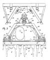
- the respective legs 26 of the trestle 25 converge upwardly and at the upper side are interconnected by means of a connecting member 27 extending at least substantially in the horizontal direction ( Figure 3).
- the connecting member 27 is provided at its front side with spaced-apart lugs 28, between which there is arranged one end of a length-adjustable rod 29, whose other end is disposed between plates 30 at the upper side of the trestle 16.
- the trestle 25 is designed as coupling part of an automatic coupling, whose other coupling part 31 is connected to the implement to be coupled to the machine, which part is shown in further detail in Figures 2 and 3.
- the coupling part 31 includes a carrier 32 which extends transversely to the direction of operative travel A and is located in an at least substantially horizontal position.
- the carrier 32 has downwardly diverging portions 33 which are U-shaped and are capable of accommodating the obliquely upwardly directed legs 26 of the trestle 25.
- the portions 33 are connected to the ends of the carrier 32 by means of supports 34.
- the trestle 25 forming part of the coupling means 17 can be positioned under the coupling part 31 connected to the implement by means of frame portions 35 and 36, whereafter the trestle can be moved upwardly. Then the portions 33 slide over the upwardly extending legs 26 of the trestle 25 and the connecting member 27 of the trestle 25 comes to bear on the lower side of the carrier 32, it then being located partly between plates 37 provided at the bottom side of the carrier 32 and at the inner side of the portions 33.
- the machine is connected to the three-point lifting hitch by means of the trestle 16 and is moved in a direction indicated by the arrow A.
- the soil working members 3 are rotated from the tractor via the intermediate shaft 15 and the above-described transmission, whereby adjacent soil working members 3 rotate in opposite directions and cultivate at least adjoining strips of soil by means of their soil working elements 5.
- the coupling means 17 arranged at the rear of the trestle 16 the implement combined with the machine by means of the coupling part 31 at the trestle 25 can move in height independently of the machine via the pivotal connection of the arms 18, the rod 29 and the trestle 25.
- the downward movement of the trestle 25 is limited by means of lengthadjustable chains 41 arranged between the arms 18 and the plates 30 of the trestle 16, which is of importance in particular during transportation.
- the trestle 25 is positioned above the rear side of the frame portion 1 and is pivotal at the lower side about the shafts 23 which, relative to the direction of operative travel A, are located behind the trestle.
- the trestle 25, which forms part of the coupling means 17 and like the arms 18 and the rod 29 is provided detachably is located as closely as possible to the trestle 16 of the machine, so that the combination of machine and added implement, e.g.
- a seed drill can be positioned as closely as possible behind the tractor.
- the pivotal connec tion behind the arms 18 and the trestle 25 comprises two adjacently interspaced supporting points constituted by the strips 24 ( Figure 3).
- the spacing between said supporting points is preferably at least 10 cms.
Landscapes
- Life Sciences & Earth Sciences (AREA)
- Engineering & Computer Science (AREA)
- Mechanical Engineering (AREA)
- Soil Sciences (AREA)
- Environmental Sciences (AREA)
- Zoology (AREA)
- Agricultural Machines (AREA)
- Soil Working Implements (AREA)
Applications Claiming Priority (2)
| Application Number | Priority Date | Filing Date | Title |
|---|---|---|---|
| NL8601943A NL8601943A (nl) | 1986-07-29 | 1986-07-29 | Grondbewerkingsmachine. |
| NL8601943 | 1986-07-29 |
Publications (1)
| Publication Number | Publication Date |
|---|---|
| EP0255183A1 true EP0255183A1 (de) | 1988-02-03 |
Family
ID=19848358
Family Applications (1)
| Application Number | Title | Priority Date | Filing Date |
|---|---|---|---|
| EP87201444A Withdrawn EP0255183A1 (de) | 1986-07-29 | 1987-07-28 | Bodenbearbeitungsmaschine |
Country Status (2)
| Country | Link |
|---|---|
| EP (1) | EP0255183A1 (de) |
| NL (1) | NL8601943A (de) |
Cited By (2)
| Publication number | Priority date | Publication date | Assignee | Title |
|---|---|---|---|---|
| FR2671450A1 (fr) * | 1991-01-14 | 1992-07-17 | Sulky Burel Sa | Dispositif d'attelage d'un semoir a une machine de travail du sol. |
| EP0635194A1 (de) * | 1993-07-19 | 1995-01-25 | Kuhn S.A. | Gerätekombination zur Bodenbearbeitung und zum Säen deren Sämaschine während des Transportes gut gehalten ist |
Citations (1)
| Publication number | Priority date | Publication date | Assignee | Title |
|---|---|---|---|---|
| WO1981002086A1 (en) * | 1980-01-24 | 1981-08-06 | Bercato | Device for coupling together an implement with an implement carrier |
-
1986
- 1986-07-29 NL NL8601943A patent/NL8601943A/nl active Search and Examination
-
1987
- 1987-07-28 EP EP87201444A patent/EP0255183A1/de not_active Withdrawn
Patent Citations (1)
| Publication number | Priority date | Publication date | Assignee | Title |
|---|---|---|---|---|
| WO1981002086A1 (en) * | 1980-01-24 | 1981-08-06 | Bercato | Device for coupling together an implement with an implement carrier |
Cited By (3)
| Publication number | Priority date | Publication date | Assignee | Title |
|---|---|---|---|---|
| FR2671450A1 (fr) * | 1991-01-14 | 1992-07-17 | Sulky Burel Sa | Dispositif d'attelage d'un semoir a une machine de travail du sol. |
| EP0635194A1 (de) * | 1993-07-19 | 1995-01-25 | Kuhn S.A. | Gerätekombination zur Bodenbearbeitung und zum Säen deren Sämaschine während des Transportes gut gehalten ist |
| FR2707831A1 (fr) * | 1993-07-19 | 1995-01-27 | Kuhn Sa | Machine combinée de travail du sol et de semis dont le semoir est mieux tenu durant le transport. |
Also Published As
| Publication number | Publication date |
|---|---|
| NL8601943A (nl) | 1988-02-16 |
Similar Documents
| Publication | Publication Date | Title |
|---|---|---|
| US3931858A (en) | Cultivating machine | |
| EP0271119B1 (de) | Bodenbearbeitungsmaschine | |
| EP0198563B1 (de) | Landwirtschaftliche Maschine | |
| US4057111A (en) | Soil cultivating machines | |
| EP0475480B1 (de) | Bodenbearbeitungsmaschine | |
| EP0337533B1 (de) | Mechanisch angetriebenes Bodenbearbeitungsgerät | |
| EP0255183A1 (de) | Bodenbearbeitungsmaschine | |
| EP0436975A1 (de) | Bodenbearbeitungsmaschine | |
| EP0620962B1 (de) | Bodenbearbeitungsmaschine | |
| EP0345899A1 (de) | Bodenbearbeitungsmaschine | |
| EP0288125B2 (de) | Bodenbearbeitungsmaschine | |
| EP0305601B1 (de) | Gerät zur Bodenbearbeitung | |
| EP0262734B1 (de) | Bodenbearbeitungsmaschine | |
| US2330743A (en) | Beet lifter | |
| NL9200243A (nl) | Grondbewerkingsmachine. | |
| EP0244038B1 (de) | Bodenbearbeitungsgeräte | |
| EP0338646A2 (de) | Kultivator | |
| EP0252555B1 (de) | Bodenbearbeitungsmaschine | |
| EP0264987A1 (de) | Bodenbearbeitungsmaschine | |
| PL189826B1 (pl) | Wieloczynnościowa maszyna rolnicza do uprawy gleby i do siewu | |
| EP0269183A1 (de) | Bodenbearbeitungsmaschine | |
| EP0283078A1 (de) | Bodenbearbeitungsmaschine | |
| EP0254350B1 (de) | Bodenbearbeitungsmaschine | |
| RU2025922C1 (ru) | Сельскохозяйственный агрегат | |
| JPH07274627A (ja) | 苗移植方法並びに移植作業車 |
Legal Events
| Date | Code | Title | Description |
|---|---|---|---|
| PUAI | Public reference made under article 153(3) epc to a published international application that has entered the european phase |
Free format text: ORIGINAL CODE: 0009012 |
|
| AK | Designated contracting states |
Kind code of ref document: A1 Designated state(s): DE FR GB NL |
|
| 17P | Request for examination filed |
Effective date: 19880721 |
|
| 17Q | First examination report despatched |
Effective date: 19890714 |
|
| STAA | Information on the status of an ep patent application or granted ep patent |
Free format text: STATUS: THE APPLICATION IS DEEMED TO BE WITHDRAWN |
|
| 18D | Application deemed to be withdrawn |
Effective date: 19910702 |
|
| RIN1 | Information on inventor provided before grant (corrected) |
Inventor name: BOM, CORNELIS JOHANNES GERARDUS Inventor name: VAN DER LELY, ARY |