EP0255253B1 - Beweglicher Ständer - Google Patents
Beweglicher Ständer Download PDFInfo
- Publication number
- EP0255253B1 EP0255253B1 EP87306127A EP87306127A EP0255253B1 EP 0255253 B1 EP0255253 B1 EP 0255253B1 EP 87306127 A EP87306127 A EP 87306127A EP 87306127 A EP87306127 A EP 87306127A EP 0255253 B1 EP0255253 B1 EP 0255253B1
- Authority
- EP
- European Patent Office
- Prior art keywords
- arm
- bracket
- stand
- cup
- arm assembly
- Prior art date
- Legal status (The legal status is an assumption and is not a legal conclusion. Google has not performed a legal analysis and makes no representation as to the accuracy of the status listed.)
- Expired - Lifetime
Links
- 230000006835 compression Effects 0.000 claims description 15
- 238000007906 compression Methods 0.000 claims description 15
- 230000000712 assembly Effects 0.000 claims description 10
- 238000000429 assembly Methods 0.000 claims description 10
- 230000002093 peripheral effect Effects 0.000 claims description 10
- 230000005484 gravity Effects 0.000 claims description 2
- 230000013011 mating Effects 0.000 claims description 2
- 230000001419 dependent effect Effects 0.000 claims 2
- 230000002401 inhibitory effect Effects 0.000 claims 1
- 230000000284 resting effect Effects 0.000 claims 1
- 230000008878 coupling Effects 0.000 description 11
- 238000010168 coupling process Methods 0.000 description 11
- 238000005859 coupling reaction Methods 0.000 description 11
- 230000000694 effects Effects 0.000 description 7
- 210000003128 head Anatomy 0.000 description 5
- 238000010276 construction Methods 0.000 description 4
- 238000010586 diagram Methods 0.000 description 4
- 230000004048 modification Effects 0.000 description 3
- 238000012986 modification Methods 0.000 description 3
- 238000006073 displacement reaction Methods 0.000 description 2
- 238000003780 insertion Methods 0.000 description 2
- 230000037431 insertion Effects 0.000 description 2
- 230000001427 coherent effect Effects 0.000 description 1
- 230000000295 complement effect Effects 0.000 description 1
- 239000000470 constituent Substances 0.000 description 1
- 230000001747 exhibiting effect Effects 0.000 description 1
- 239000007787 solid Substances 0.000 description 1
Images










Classifications
-
- F—MECHANICAL ENGINEERING; LIGHTING; HEATING; WEAPONS; BLASTING
- F16—ENGINEERING ELEMENTS AND UNITS; GENERAL MEASURES FOR PRODUCING AND MAINTAINING EFFECTIVE FUNCTIONING OF MACHINES OR INSTALLATIONS; THERMAL INSULATION IN GENERAL
- F16M—FRAMES, CASINGS OR BEDS OF ENGINES, MACHINES OR APPARATUS, NOT SPECIFIC TO ENGINES, MACHINES OR APPARATUS PROVIDED FOR ELSEWHERE; STANDS; SUPPORTS
- F16M11/00—Stands or trestles as supports for apparatus or articles placed thereon ; Stands for scientific apparatus such as gravitational force meters
- F16M11/02—Heads
- F16M11/04—Means for attachment of apparatus; Means allowing adjustment of the apparatus relatively to the stand
- F16M11/06—Means for attachment of apparatus; Means allowing adjustment of the apparatus relatively to the stand allowing pivoting
- F16M11/10—Means for attachment of apparatus; Means allowing adjustment of the apparatus relatively to the stand allowing pivoting around a horizontal axis
-
- F—MECHANICAL ENGINEERING; LIGHTING; HEATING; WEAPONS; BLASTING
- F16—ENGINEERING ELEMENTS AND UNITS; GENERAL MEASURES FOR PRODUCING AND MAINTAINING EFFECTIVE FUNCTIONING OF MACHINES OR INSTALLATIONS; THERMAL INSULATION IN GENERAL
- F16M—FRAMES, CASINGS OR BEDS OF ENGINES, MACHINES OR APPARATUS, NOT SPECIFIC TO ENGINES, MACHINES OR APPARATUS PROVIDED FOR ELSEWHERE; STANDS; SUPPORTS
- F16M11/00—Stands or trestles as supports for apparatus or articles placed thereon ; Stands for scientific apparatus such as gravitational force meters
- F16M11/20—Undercarriages with or without wheels
- F16M11/2007—Undercarriages with or without wheels comprising means allowing pivoting adjustment
- F16M11/2035—Undercarriages with or without wheels comprising means allowing pivoting adjustment in more than one direction
- F16M11/2064—Undercarriages with or without wheels comprising means allowing pivoting adjustment in more than one direction for tilting and panning
-
- F—MECHANICAL ENGINEERING; LIGHTING; HEATING; WEAPONS; BLASTING
- F21—LIGHTING
- F21V—FUNCTIONAL FEATURES OR DETAILS OF LIGHTING DEVICES OR SYSTEMS THEREOF; STRUCTURAL COMBINATIONS OF LIGHTING DEVICES WITH OTHER ARTICLES, NOT OTHERWISE PROVIDED FOR
- F21V21/00—Supporting, suspending, or attaching arrangements for lighting devices; Hand grips
- F21V21/14—Adjustable mountings
- F21V21/26—Pivoted arms
-
- F—MECHANICAL ENGINEERING; LIGHTING; HEATING; WEAPONS; BLASTING
- F16—ENGINEERING ELEMENTS AND UNITS; GENERAL MEASURES FOR PRODUCING AND MAINTAINING EFFECTIVE FUNCTIONING OF MACHINES OR INSTALLATIONS; THERMAL INSULATION IN GENERAL
- F16M—FRAMES, CASINGS OR BEDS OF ENGINES, MACHINES OR APPARATUS, NOT SPECIFIC TO ENGINES, MACHINES OR APPARATUS PROVIDED FOR ELSEWHERE; STANDS; SUPPORTS
- F16M2200/00—Details of stands or supports
- F16M2200/02—Locking means
- F16M2200/021—Locking means for rotational movement
- F16M2200/024—Locking means for rotational movement by positive interaction, e.g. male-female connections
-
- F—MECHANICAL ENGINEERING; LIGHTING; HEATING; WEAPONS; BLASTING
- F16—ENGINEERING ELEMENTS AND UNITS; GENERAL MEASURES FOR PRODUCING AND MAINTAINING EFFECTIVE FUNCTIONING OF MACHINES OR INSTALLATIONS; THERMAL INSULATION IN GENERAL
- F16M—FRAMES, CASINGS OR BEDS OF ENGINES, MACHINES OR APPARATUS, NOT SPECIFIC TO ENGINES, MACHINES OR APPARATUS PROVIDED FOR ELSEWHERE; STANDS; SUPPORTS
- F16M2200/00—Details of stands or supports
- F16M2200/04—Balancing means
- F16M2200/044—Balancing means for balancing rotational movement of the undercarriage
-
- F—MECHANICAL ENGINEERING; LIGHTING; HEATING; WEAPONS; BLASTING
- F16—ENGINEERING ELEMENTS AND UNITS; GENERAL MEASURES FOR PRODUCING AND MAINTAINING EFFECTIVE FUNCTIONING OF MACHINES OR INSTALLATIONS; THERMAL INSULATION IN GENERAL
- F16M—FRAMES, CASINGS OR BEDS OF ENGINES, MACHINES OR APPARATUS, NOT SPECIFIC TO ENGINES, MACHINES OR APPARATUS PROVIDED FOR ELSEWHERE; STANDS; SUPPORTS
- F16M2200/00—Details of stands or supports
- F16M2200/06—Arms
- F16M2200/065—Arms with a special structure, e.g. reinforced or adapted for space reduction
Definitions
- the present invention relates to a movable stand employing a parallel arm assembly, and more particularly to such a movable stand in which one of the parallel arm members is shaped into a tubular configuration in order to conceal therein the other parallel arm member.
- Movable stands employing a parallel arm mechanism have been conventionally utilized for carrying head units of such as lamps or book holders to be installed adjacent desks, beds or the like places.
- Such movable stands are disclosed in U.S. Patent Nos. 4 080 530, 4 160 536, 4 165 530 and 4 213 172.
- a pair of arm members forms an arm assembly in combination with a pair of brackets pivotally connected to each end thereof, the arm assembly additionally including a spring which provides a counterbalancing effect thereon.
- Any of these prior movable stands employs a parallel crank of a primitive configuration such that a parallelogram structure is explicitly exposed thereby presenting a definite gap between two parallel arm members.
- An arm assembly having such a primitive configuration inherently accompanies the characteristics thereof which determines that the gap width between arms varies as the arm assembly swings.
- the gap width practically reaches its maximum when the arm assembly extends vertically and the gap is gradually reduced as the reclining angle is increased until it reaches its minimum when the arm assembly extends horizontally.
- the variations in the width of the exposed gap between the arms during the swing motion of the arm assembly results in a constant danger that a user's fingers will be pinched between the two parallel arm members when trying to adjust the angular position of the movable stand from an upright position to a horizontal position with the attendant narrowing of the gap.
- the European Search Report has revealed DT 2 605 126 AI (Thiele) and the disclosure thereof forms the basis for the preamble of the main claim herein.
- a movable stand comprising: a pair of arms and a pair of brackets pivoted together so as to form an arm assembly, means to attach one of the brackets to a support, object attaching means to attach the other bracket to an object to be supported by the stand, one of the arms being in the form of a sleeve enclosing the other arm, spring means which exerts a counterbalancing, spring force upon the pair of said arms for holding the arm assembly at a desired angular position with respect to the support means, said spring means being enclosed within said one tubular arm with one end anchored to said other arm and the other end being connected to slider means which is slidable lengthwise with respect to said other arm, connecting means connecting the slider means to the adjacent bracket such that when the arm assembly is swung downwardly the spring means is stressed longitudinally of the ot.her arm thereby to transmit to the arm assembly a spring force counterbalancing the gravity force acting on the arm assembly, characterised in that said connecting means connects said slider means to
- the or each arm assembly presents a single-arm-like structure realising an aesthetic appeal and at the same time giving no externally accessible gap between the arm members which would be otherwise the cause of undesirable finger entrapment.
- the movable stand defined above distinguishes from Thiele in reciting that the connecting means connects the slider means to the first-mentioned bracket at an angle with respect to the longitudinal axis of said one arm. This arrangement, which enhances the ability of the spring means to counterbalance the gravitational forces acting on the arm assembly, is not foreseen by Thiele.
- Embodiments of the present invention provide a movable stand in which counterbalancing means is hidden within the arm assembly structure, thereby presenting a smart and stylish design.
- a movable stand in accordance with a first embodiment includes first and second arm assemblies 2 and 3 which are articulated to each other through a middle bracket 5.
- the lower end of the first arm assembly 2 is connected by means of a bottom bracket 4 to a mounting stem 12 which defines a swivel pivot with a suitable mounting base (not shown).
- the upper end of the second arm assembly 3 is connected through a top bracket 6 to a lamp unit 7.
- An electric cord 400 with a plug 401 is routed through the inside of the movable stand to supply electric power to lamp unit 7. As depicted in Figs.
- the first arm assembly 2 consists basically of an outer arm 60 of tubular configuration and an inner arm rod 70 which are pivoted at their respective ends to bottom and middle brackets 4 and 5 to form the first assembly.
- the second arm assembly 3 consists basically of an outer arm 140 of tubular configuration and an inner arm rod 150 which are pivoted at their respective ends to middle and top brackets 5 and 6 to form the second assembly.
- counterbalancing springs 80 and 160 are disposed around respective ones of the inner arm rods 70 and 150 for providing a counterbalancing effect upon each of the arm assemblies.
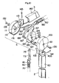
- Bottom bracket 4 comprises a disc 30 and a first pair of opposed cup-shaped bracket members 10 and 20 which each have a generally circular outer configuration and together enclose therebetween disc 30.
- One bracket member 10 is formed integrally with an extension 11 having the mounting stem 12 projecting outwardly therefrom.
- On the inner surface of the bracket member 10 there is integrally formed a center boss 13 with an opening 14, a pair of spaced studs 15 and an arcuate projection 16 extending along, and inwardly of, the inner periphery of the surrounding wall.
- the other bracket member 20 has integrally formed thereon a coupling sleeve 21 projecting outwardly for connection with the outer tubular arm 60 of the first arm assembly 2.
- the coupling sleeve 21 is inserted into the lower end of tubular arm 60 and secured thereto by a rivet 62 so that the bracket member 20 is movable with the outer tubular arm 60.
- a central opening 22 with a square-shaped cavity 23 is formed at the center of bracket member 20. Cavity 23 extends into a central boss 24 which itself projects inwardly into the bracket member 20, as best shown in Fig. 6.
- a stopper projection 25 is also formed at the interior of the bracket member 20. This stopper projection 25 is provided to limit the angular displacement of the bracket member 20 relative to the bracket member 10.
- Disc 30 is fixed to the bracket member 10.
- the stopper projection 25 co-operates with an adjacent projection 26 to hold therebetween the electric cord 400.
- Cord 400 enters the bracket member 20 through a bushing 402, which bushing 402 is located by a notch 27 of the peripheral wall.
- Cord 400 extends upwardly from the bushing member 20 through the coupling sleeve 21.
- the bracket disc 30 is attached to the bracket member 10 by means of the studs 15 which extend into holes in disc 30. It is secured thereto by screws 37 which extend through apertures 31 in disc 30 and engage threaded bores in center boss 13 (Fig. 3). In the periphery of the disc 30 there is formed a pair of diametrically opposed cutouts 32 and 33, one for snugly receiving arcuate projection 16 and the other for receiving therein stopper projection 25. This arrangement allows the above-mentioned limited angular movement of the bracket member 20 relative to the other bracket member 10.
- a pair of pivot pins 35 and 36 are provided on the disc 30 and arranged to be disposed generally oppositely relative to a central hole 34.
- Bracket member 20 is fixed to tubular arm 60 to be movable therewith. It is coupled with bracket member 10 by means of a center pin 50 which extends through the central opening 22, a bearing sleeve 56, which is fitted into the central hole 34 of disc 30, and the opening 14 in bracket member 10.
- the center pin 50 is formed with a square neck 51 adjacent its head, a bifurcated end 55, and has an internal thread 54. The square neck 51 is fitted into the square cavity 23 of the bracket member 20 thereby ensuring that the center pin 51 is rotatable with the bracket member 20 and thus the outer tubular arm 60 also.
- center pin 50 which coaxially couples the bracket members 10 and 20, is also the means of the pivotal connection of disc 30 or bottom bracket 4 with outer tubular arm 60 for completing the parallel arm of the first arm assembly.
- This arrangement contributes to a reduction in the number of pivot pins required for the assembly.
- all the components, which afford the pivotal connection between the disc 30 and its associated members, are concealed between the bracket members 10 and 20 thereby providing a neat finish at the junction between bottom bracket 4 and outer tubular arm 60 as a feature of the outer appearance of the first arm assembly 2.
- a friction ring 40 is interposed between the peripheral walls of bracket members 10 and 20.
- This friction ring 40 is provided with a pair of prongs 41 which are engaged with the opposite ends of arcuate projection 16 of bracket member 10, whereby ring 40 is rotatable therewith.
- the friction ring 40 provides a friction coupling between bracket member 10 and the other bracket member 2C. This arrangement ensures that a frictional force is exerted between bracket members 10 and 20.
- This frictional force is additional to the spring force exerted by the counterbalancing spring 80 for balancing the first arm assembly 2 and keeping it at a desired angular position about bottom bracket 4.
- This frictional force may be easily adjusted by tightening or loosening adjusting screw 59 by means of a screw driver or like.
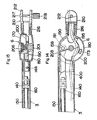
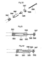
- the inner arm rod 70 is formed with a rounded shank and a flat lower end 71.
- An upper joint member 73 is secured at its bottom to an upper end of the shank of rod 70 by means of a bolt 76.
- the counterbalancing spring 80 which is a compression spring, is placed around the rounded shank portion of inner arm rod 70. Its upper end is held against the lower end of upper joint member 73 via a bushing 81.
- the lower end of spring 80 abuts via a bushing 82 against a slider 83.
- the slider 83 is so mounted on the inner arm rod 70 as to be slidable along the length of the rounded portion thereof, as best shown in Figs. 3 and 19.
- An upper end of a spring actuator bar 84 is pivotally connected to slider 83.
- the bar 84 has an apertured upper end into which the rounded portion of inner arm rod 70 loosely extends. This arrangement enables the upper end of bar 84 to be movable with slider 83 when the bar 84 is pivoted relative thereto.
- the spring actuator bar 84 has its lower pivot axis X offset oppositely of the pivot axis A of outer tubular arm 60 relative to the pivot axis B of inner arm rod 70. This arrangement causes the bar 84 to be so inclined relative to the longitudinal axis of outer tubular arm 60 at such an angle as to ensure an increased compression rate of spring 80 as the arm assembly swings downwardly.
- the lower end 71 of the inner arm rod 70 and the lower end of spring actuator bar 84 which both extend into the bottom bracket 4, are flat shaped.
- This configuration of rod 70 and bar 84 enables the thickness of the bottom bracket 4 to be minimised.
- the lower flat portion of spring actuator bar 84 is arcuately shaped with its convex side located adjacent to the inner arm rod 70. It is situated so that the upper portion thereof overlaps with the inner arm rod 70. This reduces the required width dimension of outer tubular arm 60 to a minimum, while ensuring enough space inside of outer tubular arm 60 to permit the electric cord 400 to pass therethrough without hindrance throughout the range of the swinging movement of arm assembly 2 between a generally upright position of Fig. 8 and a horizontal position of Fig. 9.
- the first arm assembly 2 is movable between the positions of Figs. 8 and 9. In each of these positions, the stopper projection 25, which is integral with bracket member 20 and therefore movable with outer tubular arm 60, engages with a corresponding edge of cutout 33 in disc 30.
- the inside diameter of spring 80 is slightly greater than the outside diameter of the rounded portion of inner arm rod 70 so that it can be compressed lengthwise thereof without accompanying substantial distortion in the lateral direction.
- Each of bushings 81 and 82 on the ends of spring 80 is kept in a sliding contact with the inner surface; of the pair of opposed walls of arm 60 with the closest spacing, as best shown in Fig. 5. This arrangement allows spring 80 to be guided by these walls along a substantially straight path during its compression stroke. This arrangement also serves to prevent the buckling of inner arm rod 70 during repeated swinging movements of the arm assembly.
- the middle bracket 5 comprises a second bracket disc 120 and a second pair of opposed cup-shaped bracket members 100 and 110 which have generally circular outer configuration and which enclose therebetween a disc 120.
- One bracket member 100 is formed integrally with a coupling sleeve 102 projecting outwardly therefrom.
- Sleeve 102 is formed for insertion into the upper end of the outer tubular arm 60 of the first arm assembly 2.
- Sleeve 102 is secured to outer tubular arm 60 by a rivet 64. This arrangement ensures that bracket member 100 is movable with the outer tubular arm 60.
- the other bracket member 110 is formed integrally with a coupling sleeve 113.
- Sleeve 113 is coupled to the outer tubular arm 140 of the second arm assembly 3 by means of a rivet 143.
- the disc 120 is held coaxially between the bracket members 100 and 110 by means of a center pin 130.
- Pin 130 extends through a central opening 101 in bracket member 100, a flanged central hole 121 in disc 120, and a central boss 111 of bracket member 110.
- Pin 130 defines a common pivot axis for the outer tubular arm 60 of the first arm assembly 2 and as well for the outer tubular arm 140 of the second arm assembly 3.
- the disc 120 is provided on one face with a pivot pin 123. This pin 123 together with an eyelet 78 is received in an eye (aperture) 75 at the upper end of inner arm rod 70 of the first arm assembly 2.
- second disc 120 pivotally supports the upper end of the first arm assembly 2 and the lower end of the second arm assembly 3.
- the center pin 130 has a square neck fitted in a correspondingly shaped cavity in the center opening 101 and is thereby movable with the bracket 100.
- An adjusting screw 132 engages with an internal thread in the end of center pin 130 in order to hold bracket members 100 and 110 together.
- a washer 133 is interposed between the head of screw 132 and the bottom of a central recess formed in the outer surface of bracket member 110 as the counterpart of central boss 111.
- the disc 120 has its peripheral portion in frictional engagement respectively with arcuate ribs 115 and 116 each projecting interiorly of each of bracket members 100 and 110 in closely spaced relation with the peripheral wall thereof.
- disc 120 is rotatable relative to each of bracket members 100 and 110 with a friction fit and it is also floatingly supported between bracket members 100 and 110.
- the frictional force may be adjusted by means of the screw 132 to be a moderate value such that the middle bracket 5 acts as a floating bracket ensuring a coherent movement of the first and second arm assemblies 2 and 3 throughout the range of the swinging movement thereof.
- the bracket members 100 and 110 have their peripheral edges separated by a small clearance T. This avoids an additional frictional coupling therebetween. Provision is made to ensure that the interior of middle bracket 5 is not visible through clearance T.
- a fringe (or skirt) 117 projects from the periphery of bracket member 100 into a mating recess 118 in the periphery of the opposed bracket member 110. The arrangement is such that the fringe 117 bridges the clearance T without causing any clirect frictional engagement therebetween.
- the disc 120 has an arcuate recess 126.
- a bore 127 is arranged at one circumferential end of recess 126.
- the bore 127 enables the electric cord 400 to extend upwardly from outer tubular arm 60.
- the cord 400 passes through the bore 127 into outer tubular arm 140 of the second arm assembly 3.
- a portion of cord 400 is guided along the arcuate recess 126.
- the inner arm rod 150, spring actuator bar 164, and compression spring 160 of the second arm assembly 3 each have an identical construction and function to those of the first arm assembly 2. Therefore, no further explanation thereof is deemed necessary.
- the top bracket 6 comprises a third disc 190 and a third pair of opposed cup-shaped bracket members 170 and 180.
- Members 170, 180 each have generally circular outer configuration and together they enclose therebetween the disc 190.
- the bracket member 170 is formed integrally with a coupling sleeve 175. This sleeve 175 is inserted into the upper end of the outer tubular arm 140 of the second arm assembly 3. It is secured thereto by a rivet 144 so that it is movable with outer tubular arm 140.
- the other bracket member 180 has an integral support 182 which enables a connection to be made to an end attachment 210 supporting the lamp unit 7.
- the disc 190 is attached to the bracket member 180 by screws 197, in the same manner as in bottom bracket 4.
- the disc 190 carries a pivot pin 191 which is spaced radially outwardly relative to a central hole 196. This pin 191 together with an eyelet 158 is received in an eye 154 at the upper end of inner arm rod 150. This arrangement makes a pivotal connection.
- the bracket members 170 and 180 with disc 190 interposed therebetween are connected by means of a center pin 201.
- Pin 201 passes through bearing sleeve 203 and an adjusting screw 206.
- These components 201, 203 and 206 are each identical in structure and function to the correponding parts 50, 56 and 59 in bottom bracket 4.
- Center pin 201 extends through a central opening 181 of bracket member 180, through bearing sleeve 203 (which fits in the central hole 196 of disc 190), and through a central boss 171 of the bracket member 170.
- a friction ring 200 is located between the peripheries of bracket members 170 and 180. This ring 200 provides a frictional coupling between bracket members 170 and 180.
- the force of this friction coupling may be adjusted for the purpose of properly balancing the weight of the second arm assembly 3 and lamp unit 7 supported thereby with the effect of the counterbalancing spring 160.
- the bracket member 170 On an internal portion of its peripheral wall, the bracket member 170 is provided with an integral stopper (or abutment) 173. This stopper co-operates with an arcuate notch 194 formed in the periphery of disc 190 thereby to limit the angular movement of the bracket member 180 and therewith the mounting lamp unit 7 relative to the bracket member 170 and thereby the second arm assembly 3.
- the electric cord 400 extends out of the outer tubular arm 140 and it is then routed through a notch 195 in the disc 190, through support 182, and through an end attachment 210 to the lamp unit 7.
- the end attachment 210 includes a hinge joint 212 which has an externally threaded pipe 211.
- This pipe 211 is compressible so as to contract in diameter when a tapered unit is applied thereto. As shown in Figs. 14 and 15, the pipe 211 will tightly grip the support 182 when inserted therein and when thereafter the tapered nut 216 is tightened on pipe 211. This enables a secure connection thereof to the top bracket 6.
- the hinge joint 212 has a nut 218 and bolt 217 for mounting the lamp unit 7.
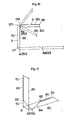
- Fig. 16 in the movable stand thus constructed, the first and second arm assemblies 2 and 3 are allowed to swing in association with each other into pasitions indicated by solid and dotted lines while pivoting about corresponding pivot axes A1 and A2 defined by center pins 50 and 130, respectively.
- Fig. 18 which is similar to Fig. 17, shows how the compression spring 160 is compressed as the second arm assembly 3 swings downwardly to effect a counterbalancing effect thereon.
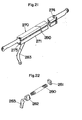
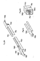
- Figs. 20 and 21 each show another form of an inner arm and spring combination, each of which may be substituted for the combination of Fig. 19.
- the combination of Fig. 20 includes an inner arm bar 250 of flat shape, with a pair of bearing blocks 262 and 263 arranged in longitudinally spaced relation and mounted on one side thereof.
- a shaft 261 extends in parallel-relation with the inner arm bar 250 and through bearing blocks 262 and 263, by which it is slidably supported.
- a compression spring 260 is arranged on shaft 261 and disposed with one end held against bearing block 262 and with the other end held against a bushing 264. This bushing 264 is fixed to the shaft 261 inwardly of the other bearing block 263.
- the end of shaft 261 adjacent the bushing 264 is pivoted to one end of a spring actuator bar 265.
- the arrangement is such that when the actuator bar 265 is pivoted, then it pushes the shaft 261 and the bushing 264 thereon in the direction of compression spring 260.
- the bar 265 is caused to pivot about its other end during a downward swinging movement of the corresponding arm assembly. This displacement of spring 260 gives rise to the equivalent counterbalancing effect.
- an inner arm 270 is formed along a middle portion thereof with an integral sheath 271 for accommodating therein a compression spring 280.
- the sheath 271 also encloses a stop pad 281 and a shoe 282 between which the spring 280 is compressed, as shown in Fig. 22.
- the stop pad 281 is held against an inwardly directed projection 274 at one end of sheath 171.
- the shoe 282 is located so as to be slidable within and along the length of the sheath 171.
- a spring actuator bar 283 has a portion which extends into sheath 271 through a slit 275 therein. This bar 283 is arranged to be pivotally connected to the shoe 282 in such manner that it may push the shoe 282 to compress the spring 280. This compression occurs when the actuator bar 283 pivots about the other end during the downward swinging movement of the arm assembly.
- Fig. 23 shows a modified form of a bracket disc 300 which may be substituted for the disc 120 of the middle bracket 5.
- the disc 300 is formed with an elongated slot 302 which extends in a correspondingly arcuate recess 301 in the peripheral portion of the disc 300.
- the slot 302 receives the electric cord 400 and allows it to be freely movable therein. This arrangement is effective for protecting cord 400 from being damaged during articulated movement of the adjacent arm assemblies relative to disc 300.
- the disc 300 is illustrated, for the sake of simplicity only, without associated pivot pins.
- FIG. 24 A modified form of a counterbalancing mechanism is shown schematically in Fig. 24.
- This mechanism may be used in either of the first or the second arm assembly above described.
- a tension spring 80b is employed instead of a compression spring 80.
- This spring 80b has one end fixed at F to the lower end of an inner arm member 70b and it has the other end M mounted to be slidable along the length thereof.
- the other end M of spring 80b is pivotally connected to one end of a spring actuator 84b.
- This actuator 84b is inclined at an angle with respect to the longitudinal axis of an outer tubular arm 60b and it is pivotally supported at point P by means of an associated bracket (not shown).
- the above-mentioned movable stand with its double-arm assembly may be readily modified to provide a movable stand with a single-arm assembly as shown in Fig. 25.
- the construction of this modified movable stand is such that the upper arm assembly and the middle bracket are eliminated from the previous embodiment, and in addition the top bracket thereof is directly connected to the lower arm assembly.
- this modified movable stand corresponds substantially to the lower arm assembly of the previously described embodiment concerning its construction and function.
- the constituent parts of this modification are desiqnated by the same reference numeral as the counterparts of the above first embodiment with the addition of the lower case letter (a).
- the number of arm assemblies may be arbitrarily selected when designing a movable stand: when choosing a plurality of arm assemblies, it is simply necessary to provide the corresponding number of middle brackets.
Landscapes
- Engineering & Computer Science (AREA)
- General Engineering & Computer Science (AREA)
- Mechanical Engineering (AREA)
- Holders For Apparel And Elements Relating To Apparel (AREA)
- Vehicle Body Suspensions (AREA)
- Power Steering Mechanism (AREA)
- Warehouses Or Storage Devices (AREA)
Claims (20)
Applications Claiming Priority (4)
| Application Number | Priority Date | Filing Date | Title |
|---|---|---|---|
| JP11572586 | 1986-07-28 | ||
| JP115725/86 | 1986-07-28 | ||
| JP102602/87 | 1987-04-25 | ||
| JP62102602A JPH07118213B2 (ja) | 1986-07-28 | 1987-04-25 | 平行クランク式可動ア−ム |
Publications (3)
| Publication Number | Publication Date |
|---|---|
| EP0255253A2 EP0255253A2 (de) | 1988-02-03 |
| EP0255253A3 EP0255253A3 (en) | 1989-01-25 |
| EP0255253B1 true EP0255253B1 (de) | 1990-12-19 |
Family
ID=26443288
Family Applications (1)
| Application Number | Title | Priority Date | Filing Date |
|---|---|---|---|
| EP87306127A Expired - Lifetime EP0255253B1 (de) | 1986-07-28 | 1987-07-10 | Beweglicher Ständer |
Country Status (4)
| Country | Link |
|---|---|
| US (1) | US4770384A (de) |
| EP (1) | EP0255253B1 (de) |
| DE (1) | DE3766768D1 (de) |
| NO (1) | NO173201C (de) |
Cited By (3)
| Publication number | Priority date | Publication date | Assignee | Title |
|---|---|---|---|---|
| EP1015140B2 (de) † | 1997-03-04 | 2005-12-07 | CORAL S.p.A. | Allzweckrohrleitung zum ableiten von schädlichen rauchgasen von einer arbeitsstation |
| CN109923342A (zh) * | 2016-11-10 | 2019-06-21 | 赛峰座椅美国有限责任公司 | 同心视频臂枢轴机构 |
| CN110630867A (zh) * | 2019-09-27 | 2019-12-31 | 联想(北京)有限公司 | 一种电子设备及其支撑结构 |
Families Citing this family (79)
| Publication number | Priority date | Publication date | Assignee | Title |
|---|---|---|---|---|
| IT1217683B (it) * | 1988-05-20 | 1990-03-30 | Artemide Spa | Apparecchio per l'illuminazione artificiale a bracci snodati |
| CA1316886C (en) * | 1988-06-17 | 1993-04-27 | Miroslav J. Vlasak | Adjustable stand for supporting a lamp housing |
| US4846434A (en) * | 1988-08-04 | 1989-07-11 | Jac Jacobsen Industrier A.S. | Counterbalanced arm assembly |
| US5147078A (en) * | 1989-11-20 | 1992-09-15 | Flieder Joseph M | Retractable automotive clothesline |
| US4989229A (en) * | 1989-11-22 | 1991-01-29 | Picker International, Inc. | Counterbalance assembly for diagnostic imaging equipment |
| US5025359A (en) * | 1990-03-16 | 1991-06-18 | American Sterilizer Company | Counterbalanced arm for a lighthead |
| USD326535S (en) | 1990-09-05 | 1992-05-26 | Fantasy Int. Corp. | Desk lamp |
| USD334439S (en) | 1990-10-12 | 1993-03-30 | Dazor Manufacturing Corporation | Articulated arm for a task light |
| US5170975A (en) * | 1991-06-06 | 1992-12-15 | Alan Chadwick | Articulated arm with spring for counterbalancing |
| US5422802A (en) * | 1994-05-09 | 1995-06-06 | Lin; Yeong-Shang | Universally oriented and magnetically attracted lighting fixture |
| US5746404A (en) * | 1996-02-15 | 1998-05-05 | Merko; Andrew V. | Apparatus for counterbalancing equipment |
| US6010232A (en) * | 1996-05-29 | 2000-01-04 | Chen; Franks | Lamp holder assembly |
| US5826846A (en) * | 1996-06-28 | 1998-10-27 | Hill-Rom, Inc. | Monitor arm with constant counterbalance |
| DE29709093U1 (de) * | 1997-05-23 | 1997-07-17 | Fritz Sträter GmbH, 58540 Meinerzhagen | Gelenkarm für Bürogeräte |
| DE19853494A1 (de) * | 1997-11-19 | 1999-05-20 | Wella Ag | Stativ mit einer in einem Armrohr angeordneten Druckfeder |
| DE19853495A1 (de) * | 1997-11-19 | 1999-05-20 | Wella Ag | Stativ |
| US6012821A (en) * | 1998-03-30 | 2000-01-11 | Hill-Rom, Inc. | Support arm for surgical light apparatus |
| US6328458B1 (en) | 1998-03-30 | 2001-12-11 | Hill-Rom Services, Inc. | Support arm for surgical light apparatus |
| US6409134B1 (en) * | 1999-06-07 | 2002-06-25 | Innovative Office Products, Inc. | Arm apparatus for mounting electronic devices with cable management system |
| US6478274B1 (en) | 1999-05-10 | 2002-11-12 | Innovative Office Products, Inc. | Arm apparatus for mounting electronic devices |
| US6619606B2 (en) | 1999-06-07 | 2003-09-16 | Innovative Office Products, Inc. | Arm apparatus for mounting electronic devices with cable management system |
| US6609691B2 (en) * | 1999-06-07 | 2003-08-26 | Innovative Office Products, Inc. | Arm apparatus for mounting electronic devices with cable management system |
| US6588920B2 (en) * | 2000-07-28 | 2003-07-08 | Cooper Technologies Company | Pivot mechanism for a light fixture |
| US7097145B2 (en) * | 2001-09-14 | 2006-08-29 | Hill-Rom Services, Inc. | Support arm for a surgical theater system |
| US6736364B2 (en) * | 2002-02-01 | 2004-05-18 | Innovative Office Products, Inc. | Modular mounting arm |
| CN100402922C (zh) * | 2002-02-25 | 2008-07-16 | 斯特里斯公司 | 可调节的渐进式接头制动装置 |
| DE10300620B4 (de) * | 2002-05-18 | 2017-04-13 | Carl Zeiss Meditec Ag | Trägervorrichtung für ein medizinisch-optisches Gerät |
| US7369672B2 (en) * | 2002-06-24 | 2008-05-06 | Hirschhorn Bruce D | Personal audio visual system |
| US7065811B2 (en) * | 2003-03-18 | 2006-06-27 | Hill-Rom Services, Inc. | Radial arm system for patient care equipment |
| FR2855090B1 (fr) * | 2003-05-20 | 2005-08-19 | Alumed | Appareil de deplacement et d'equilibrage d'un objet sur une grande course angulaire |
| JP2005182278A (ja) * | 2003-12-17 | 2005-07-07 | Toshiba Corp | 支持装置 |
| US7677515B2 (en) * | 2004-07-07 | 2010-03-16 | Innovative Office Products, Inc. | Arm apparatus with reinforcement |
| US8051610B2 (en) | 2004-09-22 | 2011-11-08 | Hill-Rom Services, Inc. | Patient flatwall system |
| US7763015B2 (en) | 2005-01-24 | 2010-07-27 | Intuitive Surgical Operations, Inc. | Modular manipulator support for robotic surgery |
| US7837674B2 (en) * | 2005-01-24 | 2010-11-23 | Intuitive Surgical Operations, Inc. | Compact counter balance for robotic surgical systems |
| WO2006132938A2 (en) | 2005-06-03 | 2006-12-14 | Steel Case Development Corporation | Support arm assembly |
| US7546994B2 (en) * | 2006-09-15 | 2009-06-16 | Innovative Office Products, Inc. | Extension arm with moving clevis and cable management |
| CA2693964C (en) * | 2007-07-17 | 2016-03-22 | Scott Russell | Mount and electronic display system |
| US8172421B2 (en) * | 2008-03-07 | 2012-05-08 | Dentcraft Tools Limited Partnership | Portable light assembly |
| GB0807626D0 (en) * | 2008-04-25 | 2008-06-04 | Ultra Electronics Ltd | Routing of cables |
| US8220765B2 (en) * | 2008-06-23 | 2012-07-17 | Intuitive Surgical Operations, Inc. | Spring counterbalance for rotating load |
| US8916134B2 (en) * | 2008-07-11 | 2014-12-23 | Industry-Academic Cooperation Foundation, Yonsei University | Metal nanocomposite, preparation method and use thereof |
| TWM377970U (en) * | 2009-11-17 | 2010-04-11 | Galemed Corp | Hanging device and its pivoting mechanism for medical use |
| US20110149582A1 (en) * | 2009-12-22 | 2011-06-23 | Musco Corporation | Apparatus, method, and system for adjustably affixing lighting fixtures to structures |
| US8931748B2 (en) * | 2010-06-09 | 2015-01-13 | Innovative Office Products, Llc | Articulating monitor arm with cable and spring |
| BR112012031282A2 (pt) * | 2010-06-09 | 2016-11-01 | Innovative Office Products Inc | braço monitor de articulação com corrente e mola |
| DE102011079883B4 (de) * | 2011-07-27 | 2013-02-28 | Herbert Waldmann Gmbh & Co Kg | Gelenkverbindung für Leuchtensystem |
| KR101309697B1 (ko) | 2011-12-29 | 2013-09-17 | 정상민 | 조명 장치 |
| KR101309698B1 (ko) | 2011-12-29 | 2013-09-17 | 정상민 | 조명 장치 |
| DE102012202426B4 (de) * | 2012-02-16 | 2014-05-15 | Herbert Waldmann Gmbh & Co. Kg | Universalgestänge zur Halterung eines Gegenstandes, insbesondere eines Leuchtenkopfes |
| US20140003069A1 (en) * | 2012-06-29 | 2014-01-02 | Sonneman-A Way Of Light | Articulated lamp assembly with imbeded compression springs |
| US9228729B2 (en) * | 2012-06-29 | 2016-01-05 | Contemporary Visions, L.L.C. | Lamp with a single arm |
| US9657889B1 (en) | 2013-03-15 | 2017-05-23 | Humanscale Corporation | Adjustable support arm |
| USD707740S1 (en) * | 2013-05-16 | 2014-06-24 | Engineer Inc. | Loupe |
| US8955905B2 (en) * | 2013-06-07 | 2015-02-17 | Neutral Posture, Inc. | Seating assembly having a seat-mounted attachment assembly for adjustable extension arm |
| CN104235666B (zh) * | 2013-06-13 | 2016-07-13 | 徐佳义 | 平衡臂灯 |
| TWI529044B (zh) * | 2013-12-23 | 2016-04-11 | 上銀科技股份有限公司 | Brake support arm |
| JP6781553B2 (ja) * | 2015-03-25 | 2020-11-04 | エルジー イノテック カンパニー リミテッド | ホルダーおよびこれを具備する照明装置 |
| DE102015005505B3 (de) * | 2015-04-30 | 2016-06-16 | Ziehm Imaging Gmbh | Manuell verstellbare Monitorhalterung für einen Flachbildschirm einer mobilen Diagnostikeinrichtung |
| RO131806A2 (ro) * | 2015-10-02 | 2017-04-28 | Smart Furniture S.R.L. | Lampă pliabilă cu led-uri |
| CA2959323A1 (en) * | 2016-02-29 | 2017-08-29 | Masterbrand Cabinets, Inc. | Compact drawer outlet |
| US10845000B2 (en) * | 2016-10-21 | 2020-11-24 | Colebrook Bosson Saunders (Products) Limited | Display support system |
| WO2018136786A1 (en) * | 2017-01-19 | 2018-07-26 | Jenks William | Lighting system with glare reducing light array |
| US10851938B2 (en) | 2018-04-02 | 2020-12-01 | Humanscale Corporation | Adjustable support arm |
| CA3128150A1 (en) * | 2019-01-31 | 2020-08-06 | American Sterilizer Company | Support arm for medical device support system |
| USD927044S1 (en) * | 2020-03-31 | 2021-08-03 | Koncept Technologies, Inc. | Lamp |
| TWI774275B (zh) * | 2021-03-17 | 2022-08-11 | 青輔實業股份有限公司 | 關節裝置 |
| TWI774274B (zh) * | 2021-03-17 | 2022-08-11 | 青輔實業股份有限公司 | 關節裝置 |
| EP4071406A1 (de) | 2021-04-09 | 2022-10-12 | TRUMPF Medizin Systeme GmbH + Co. KG | Joch für ein aufhängungssystem für eine medizinische leuchte, aufhängungssystem und system eines medizinischen lampenkörpers und eines aufhängungssystems |
| USD962903S1 (en) * | 2021-04-29 | 2022-09-06 | Ningbo Tuotuo River Design Company | Microphone stand |
| DE102021125578A1 (de) * | 2021-10-01 | 2023-04-06 | Occhio GmbH | Leuchte mit verschwenkbar gelagertem Leuchtenkopf |
| EP4419040B1 (de) | 2021-10-18 | 2025-06-18 | American Sterilizer Company | Lastausgleichsarm für stützsystem für medizinische vorrichtungen |
| USD1021889S1 (en) * | 2022-01-13 | 2024-04-09 | Ningbo Tuotuo River Design Company | Microphone holder |
| USD1043629S1 (en) * | 2022-06-21 | 2024-09-24 | Ningbo Tuotuo River Design Company | Microphone stand |
| USD1030725S1 (en) * | 2022-08-03 | 2024-06-11 | Ningbo Tuotuo River Design Company | Support arm |
| USD1076891S1 (en) * | 2023-08-24 | 2025-05-27 | Ningbo Tuotuo River Design Company | Support stand |
| CN221923319U (zh) * | 2024-03-19 | 2024-10-29 | 欧普照明股份有限公司 | 摆杆结构、照明灯具 |
| WO2025195244A1 (zh) * | 2024-03-19 | 2025-09-25 | 苏州欧普照明有限公司 | 枢转机构、照明灯具 |
| USD1115154S1 (en) | 2024-05-20 | 2026-02-24 | Wenlian Chen | Ring light stand with foldable and rotatable arm |
Family Cites Families (21)
| Publication number | Priority date | Publication date | Assignee | Title |
|---|---|---|---|---|
| US975070A (en) * | 1910-04-01 | 1910-11-08 | Charles H Richardson | Folding bracket. |
| US2395178A (en) * | 1943-06-07 | 1946-02-19 | Art Specialty Co | Adjustable support structure |
| FR989131A (fr) * | 1944-02-02 | 1951-09-05 | Dispositif d'articulation entre deux pièces ou organes d'un appareil ou dispositif | |
| CH250203A (de) * | 1946-04-15 | 1947-08-15 | Husy Ernst | Ständer, insbesondere für Beleuchtungslampen. |
| NL69908C (de) * | 1949-07-22 | |||
| NL122167C (de) * | 1962-02-24 | |||
| US3243497A (en) * | 1964-12-11 | 1966-03-29 | Dynapower Systems Corp Of Cali | Universal support for electrotherapeutic treatment head |
| US3374347A (en) * | 1965-08-23 | 1968-03-19 | Hirose You | Electric lamp stand |
| US3973748A (en) * | 1975-01-31 | 1976-08-10 | Konan Camera Research Institute | Sustaining device |
| DE2535607C3 (de) * | 1975-08-07 | 1980-11-06 | Erco Leuchten Gmbh, 5880 Luedenscheid | Leuchte, insbesondere Tischleuchte |
| JPS5258284A (en) * | 1975-10-28 | 1977-05-13 | Jacobsen As J | Arm with balance spring |
| DE2605126A1 (de) * | 1976-02-10 | 1977-08-11 | Helmut Thiele | Verstellbare arbeitsplatzleuchte |
| US4160536A (en) * | 1976-10-27 | 1979-07-10 | Jac. Jacobsen A/S | Counterbalanced arm |
| DE2654334A1 (de) * | 1976-11-30 | 1978-06-01 | Siemens Ag | Tragarmkonstruktion mit federgewichtsausgleich |
| CH617761A5 (en) * | 1977-01-11 | 1980-06-13 | Christian Derungs | Joint for electric work luminaires |
| IT7721939U1 (it) * | 1977-07-29 | 1979-01-29 | Bernardi Sergio | Struttura di lampada da illuminazione |
| US4166602A (en) * | 1978-05-18 | 1979-09-04 | Pennwalt Corporation | Counterbalancing mechanism for X-ray tubeheads |
| US4447031A (en) * | 1981-04-13 | 1984-05-08 | Positioning Devices, Inc. | Spring counterbalanced support arm system |
| US4494177A (en) * | 1983-04-20 | 1985-01-15 | Plan Hold Corp. | Articulated task lamp |
| US4545555A (en) * | 1984-07-02 | 1985-10-08 | Koch Mark B | Adjustable arm member for use with a lamp or the like |
| US4651966A (en) * | 1986-02-19 | 1987-03-24 | Kabushiki-Kaishi Tokyo Emix | Bracket for supporting universal arm of dental X-ray apparatus |
-
1987
- 1987-07-02 US US07/069,222 patent/US4770384A/en not_active Expired - Lifetime
- 1987-07-10 DE DE8787306127T patent/DE3766768D1/de not_active Expired - Lifetime
- 1987-07-10 EP EP87306127A patent/EP0255253B1/de not_active Expired - Lifetime
- 1987-07-27 NO NO87873146A patent/NO173201C/no not_active IP Right Cessation
Cited By (4)
| Publication number | Priority date | Publication date | Assignee | Title |
|---|---|---|---|---|
| EP1015140B2 (de) † | 1997-03-04 | 2005-12-07 | CORAL S.p.A. | Allzweckrohrleitung zum ableiten von schädlichen rauchgasen von einer arbeitsstation |
| CN109923342A (zh) * | 2016-11-10 | 2019-06-21 | 赛峰座椅美国有限责任公司 | 同心视频臂枢轴机构 |
| CN109923342B (zh) * | 2016-11-10 | 2021-08-24 | 赛峰座椅美国有限责任公司 | 同心视频臂枢轴机构 |
| CN110630867A (zh) * | 2019-09-27 | 2019-12-31 | 联想(北京)有限公司 | 一种电子设备及其支撑结构 |
Also Published As
| Publication number | Publication date |
|---|---|
| NO873146D0 (no) | 1987-07-27 |
| US4770384A (en) | 1988-09-13 |
| NO873146L (no) | 1988-01-29 |
| NO173201B (no) | 1993-08-02 |
| EP0255253A2 (de) | 1988-02-03 |
| EP0255253A3 (en) | 1989-01-25 |
| NO173201C (no) | 1993-11-10 |
| DE3766768D1 (de) | 1991-01-31 |
Similar Documents
| Publication | Publication Date | Title |
|---|---|---|
| EP0255253B1 (de) | Beweglicher Ständer | |
| KR102848446B1 (ko) | 디스플레이 지지 장치 | |
| JP2505458B2 (ja) | ガス圧ばねを備えた高さ調節可能な回転椅子 | |
| EP0379733B1 (de) | Aussenrückspiegel für ein Fahrzeug | |
| CA1088039A (en) | Movable stand particularly for lampholders and the like | |
| US2941776A (en) | Counterbalancing mechanism | |
| US6059366A (en) | Adjustable armrest for chairs | |
| CA2726429C (en) | Height adjustment mechanism for a chair | |
| US4756575A (en) | Frame assembly for a chair | |
| US4314319A (en) | Adjustable lamps | |
| US11543069B2 (en) | Hinge | |
| US3072374A (en) | Movable arm for examination light | |
| US20140077048A1 (en) | Support apparatus for display devices and other objects | |
| JP2004522918A (ja) | 平面型液晶表示画面用の支持装置 | |
| US4770382A (en) | Stand for display terminals in particular | |
| US5108061A (en) | Adjustable stand | |
| KR20030091476A (ko) | 디스플레이장치 | |
| CA2649176A1 (en) | Monitor support arm | |
| US3930594A (en) | Pivot hinge for an apparatus cover hood | |
| US5799372A (en) | System for supporting a monitor | |
| JPH0767900A (ja) | 矯正器継手 | |
| US3547390A (en) | Adjustable bracket structure | |
| US5465124A (en) | Headband with adjustable device for positioning an optical device | |
| WO2020167114A1 (en) | Balancing arm | |
| US3441311A (en) | Chair control |
Legal Events
| Date | Code | Title | Description |
|---|---|---|---|
| PUAI | Public reference made under article 153(3) epc to a published international application that has entered the european phase |
Free format text: ORIGINAL CODE: 0009012 |
|
| AK | Designated contracting states |
Kind code of ref document: A2 Designated state(s): DE GB IT |
|
| PUAL | Search report despatched |
Free format text: ORIGINAL CODE: 0009013 |
|
| AK | Designated contracting states |
Kind code of ref document: A3 Designated state(s): DE GB IT |
|
| 17P | Request for examination filed |
Effective date: 19881231 |
|
| 17Q | First examination report despatched |
Effective date: 19890907 |
|
| ITF | It: translation for a ep patent filed | ||
| GRAA | (expected) grant |
Free format text: ORIGINAL CODE: 0009210 |
|
| AK | Designated contracting states |
Kind code of ref document: B1 Designated state(s): DE GB IT |
|
| REF | Corresponds to: |
Ref document number: 3766768 Country of ref document: DE Date of ref document: 19910131 |
|
| ITTA | It: last paid annual fee | ||
| PLBE | No opposition filed within time limit |
Free format text: ORIGINAL CODE: 0009261 |
|
| STAA | Information on the status of an ep patent application or granted ep patent |
Free format text: STATUS: NO OPPOSITION FILED WITHIN TIME LIMIT |
|
| 26N | No opposition filed | ||
| REG | Reference to a national code |
Ref country code: GB Ref legal event code: 746 Effective date: 19980605 |
|
| PGFP | Annual fee paid to national office [announced via postgrant information from national office to epo] |
Ref country code: GB Payment date: 19990707 Year of fee payment: 13 |
|
| PGFP | Annual fee paid to national office [announced via postgrant information from national office to epo] |
Ref country code: DE Payment date: 19990712 Year of fee payment: 13 |
|
| PG25 | Lapsed in a contracting state [announced via postgrant information from national office to epo] |
Ref country code: GB Free format text: LAPSE BECAUSE OF NON-PAYMENT OF DUE FEES Effective date: 20000710 |
|
| GBPC | Gb: european patent ceased through non-payment of renewal fee |
Effective date: 20000710 |
|
| PG25 | Lapsed in a contracting state [announced via postgrant information from national office to epo] |
Ref country code: DE Free format text: LAPSE BECAUSE OF NON-PAYMENT OF DUE FEES Effective date: 20010501 |
|
| PG25 | Lapsed in a contracting state [announced via postgrant information from national office to epo] |
Ref country code: IT Free format text: LAPSE BECAUSE OF NON-PAYMENT OF DUE FEES Effective date: 20050710 |