EP0255336A2 - Rotationsverdrängerpumpe - Google Patents
Rotationsverdrängerpumpe Download PDFInfo
- Publication number
- EP0255336A2 EP0255336A2 EP87306650A EP87306650A EP0255336A2 EP 0255336 A2 EP0255336 A2 EP 0255336A2 EP 87306650 A EP87306650 A EP 87306650A EP 87306650 A EP87306650 A EP 87306650A EP 0255336 A2 EP0255336 A2 EP 0255336A2
- Authority
- EP
- European Patent Office
- Prior art keywords
- rotor
- drive shaft
- stator
- heat
- positive displacement
- Prior art date
- Legal status (The legal status is an assumption and is not a legal conclusion. Google has not performed a legal analysis and makes no representation as to the accuracy of the status listed.)
- Withdrawn
Links
Images


Classifications
-
- F—MECHANICAL ENGINEERING; LIGHTING; HEATING; WEAPONS; BLASTING
- F04—POSITIVE - DISPLACEMENT MACHINES FOR LIQUIDS; PUMPS FOR LIQUIDS OR ELASTIC FLUIDS
- F04C—ROTARY-PISTON, OR OSCILLATING-PISTON, POSITIVE-DISPLACEMENT MACHINES FOR LIQUIDS; ROTARY-PISTON, OR OSCILLATING-PISTON, POSITIVE-DISPLACEMENT PUMPS
- F04C14/00—Control of, monitoring of, or safety arrangements for, machines, pumps or pumping installations
- F04C14/28—Safety arrangements; Monitoring
-
- F—MECHANICAL ENGINEERING; LIGHTING; HEATING; WEAPONS; BLASTING
- F04—POSITIVE - DISPLACEMENT MACHINES FOR LIQUIDS; PUMPS FOR LIQUIDS OR ELASTIC FLUIDS
- F04C—ROTARY-PISTON, OR OSCILLATING-PISTON, POSITIVE-DISPLACEMENT MACHINES FOR LIQUIDS; ROTARY-PISTON, OR OSCILLATING-PISTON, POSITIVE-DISPLACEMENT PUMPS
- F04C15/00—Component parts, details or accessories of machines, pumps or pumping installations, not provided for in groups F04C2/00 - F04C14/00
- F04C15/0057—Driving elements, brakes, couplings, transmission specially adapted for machines or pumps
- F04C15/0076—Fixing rotors on shafts, e.g. by clamping together hub and shaft
-
- F—MECHANICAL ENGINEERING; LIGHTING; HEATING; WEAPONS; BLASTING
- F04—POSITIVE - DISPLACEMENT MACHINES FOR LIQUIDS; PUMPS FOR LIQUIDS OR ELASTIC FLUIDS
- F04C—ROTARY-PISTON, OR OSCILLATING-PISTON, POSITIVE-DISPLACEMENT MACHINES FOR LIQUIDS; ROTARY-PISTON, OR OSCILLATING-PISTON, POSITIVE-DISPLACEMENT PUMPS
- F04C2/00—Rotary-piston machines or pumps
- F04C2/08—Rotary-piston machines or pumps of intermeshing-engagement type, i.e. with engagement of co-operating members similar to that of toothed gearing
- F04C2/10—Rotary-piston machines or pumps of intermeshing-engagement type, i.e. with engagement of co-operating members similar to that of toothed gearing of internal-axis type with the outer member having more teeth or tooth-equivalents, e.g. rollers, than the inner member
- F04C2/107—Rotary-piston machines or pumps of intermeshing-engagement type, i.e. with engagement of co-operating members similar to that of toothed gearing of internal-axis type with the outer member having more teeth or tooth-equivalents, e.g. rollers, than the inner member with helical teeth
- F04C2/1071—Rotary-piston machines or pumps of intermeshing-engagement type, i.e. with engagement of co-operating members similar to that of toothed gearing of internal-axis type with the outer member having more teeth or tooth-equivalents, e.g. rollers, than the inner member with helical teeth the inner and outer member having a different number of threads and one of the two being made of elastic materials, e.g. Moineau type
Definitions
- This invention relates to rotary positive displacement progressing cavity pumps in which a rigid metallic helical rotor shaft is rotated within a fixed stator.
- the stator which is fabricated from a resilient material, such as, for example, an elastomer, has an axial longitudinal cavity therethrough, which cavity defines a helical groove.
- the rotor makes contact with the stator to form a series of cavities which move in an axial direction to form a displacement pump.
- a progressing cavity or "PC" pump Such a pump is well known and will hereinafter simply be referred to as a progressing cavity or "PC" pump.
- PC pumps find common use in industries where it is required to pump high viscosity slurries or emulsions. Since the flow of material is proportional to rotational speed, PC pumps are particularly well suited for uses involving the delivery of material in precise amounts to, for example, a continuous packaging operation.
- stator of a PC pump is generally formed of an elastomer and since the rotor must operate in tight contact with the stator, it is essential that the pump not be run dry if the integrity of the stator is to be preserved. Dry-running without passage of pumped fluid leads to overheating which, if not recognized and corrected, damages the stator. Similiarly, any blockage of an outlet valve or line beyond the PC can cause slippage of the rotor, overheating within the stator and possible damage to both stator and the pumped product. In some industries, such as in the pumping of flammable or explosive materials, such overheating must be scrupulously avoided for obvious reasons.
- US- A- 2 512 765 describes the use of an externally mounted pressure switch capable of sensing high or low outlet pressures.
- the switch controls the power supplied to the drive motor of the pump.
- US- A- 3 111 904 describes making use of heat/friction expansible brake rings which are adapted to jam the rotor motion in the event of overheating.
- US- A- 3 008 426 discloses the use of a frangible mechanical coupling which disconnects the pumping element from the pump drive in the event of mechanical failure or jamming.
- US- A- 2 778 313 describes making use of an externally mounted, electrical power switching thermostat.
- US- A- 1 426 206 describes the use of a fusible link mounted on the external casing of the pump, which link, in turn, controls an electric switch.
- US- A- 4 500 268 describes making use of a fusible locking pin release mechanism which maintains the drive shaft in a rotation mode.
- the present invention provides a rotary positive displacement progressing cavity (PC) pump having a heat-actuated, breakaway drive mechanism within the stator cavity.
- PC progressing cavity
- the invention provides a PC pump wherein the rotor is attached to the drive shaft by means of a bonded, fusible connection.
- a rotary positive displacement progresssng cavity pump having a stator, a rotor within the stator, and an inlet and outlet in the stator and a drive shaft connected to the rotor, the drive shaft-to-rotor connection comprising a heat-sensitive, breakaway bond of a heat-fusible metal alloy in an amount sufficient to provide a mechanical linkage between the drive shaft and the rotor, the metal alloy being meltable upon the generation of sufficient heat within the stator and so disconnect the mechanical linkage.
- the mechanical linkage comprises a longitudinal, cylindrical bore within the rotor having centrally located therein in fusible, metal-bonded relationship a leading end of the drive shaft.
- the drive shaft leading end may have a helical groove indented upon its surface. Furthermore the drive shaft leading end may be centered within the cylindrical bore by means of plastic bushings.
- the rotor when heated by excess friction or dry-running conditions within the stator, efficiently transmits heat to its core and to the heat fusible metal bond, which bond softens and causes mechanical disconnection of the rotor from the drive shaft.
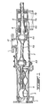
- a conventional positive displacement progressive cavity pump assembly 1 consisting of an inlet chamber 2, a drive shaft support housing 3 and a stator 4.
- a metal, helical rotor 5 is shown located in stator 4.
- a sectional drive shaft 6 (shown as 6A and 6B) is shown connected to rotor 5.
- Drive shaft 6A is supported by bearings 7 (shown as 7A and 7B).
- Two gear Universal joints 8A and 8B are provided in drive shaft 6.
- a seal 9 is provided around drive shaft 6A.
- Product to be pumped is introduced into inlet chamber 2 through opening 10 and is delivered by the pump through exit 11.
- the drive shafts 6A and 6B and connected rotor 5 are rotated within the assembly by an electric or hydraulic motor (not shown).
- rotor 5 is shown having a longitudinal, aligned, cylindrical bore 12 therein.
- An extension 13 of the drive shaft is shown fitted centrally within cylindrical bore 12.
- Fusible metallic binding material 14 is chosen from those metal alloys known to possess high mechanical or physical strength yet which have very low melting temperatures.
- Bismuth alloys such as CERRO (Trade Mark) alloys available from Cerro Metal Products of Bellefonte, Pennsylvania, U.S.A., are particularly preferred. Such alloys are available in a range of suitable melting temperatures and physical strengths and, as well, possess moulding characteristics.
- Drive shaft extension 13 may be simply bonded to rotor 5 by spacing the extension 13 centrally within cylindrical bore 12 and introducing the molten metal binding material 14 into the axial space between extension 13 and the wall of cylindrical bore 12. After solidification, a strong mechanical bond is created. In the event of high temperature generation within stator 4 during operation of the pump, heat is absorbed by rotor 5 and transmitted to the fusible metal bond 14. When sufficient heat has been transmitted to the core of rotor 5, metal 14 softens and the mechanical connection between shaft extension 13 and rotor 5 is broken, thus stopping the functioning of the pump.
- a substitute rotor/shaft extension combination can be attached to drive shaft 6, the pump reassembled and the pumping operation resumed. In some instances, it will be possible to simply allow the pump assembly to cool, thus resolidifying the metal binding material 14 without the necessity of dismantling the pump.
- Figure 3 shows the embodiment of Fi gure 2 wherein shaft extension 13 has on its surface a helical groove 15. Additionally, shaft extension 13 is shown centered and supported at each of its ends by plastic bushings 16 (shown as 16A and 16B).
- the configuration shown in Figure 3 is particularly adapted for use in operations where explosive or other heat-sensitive materials are to be pumped.
- the fusible metal 14 when molten is augered out of cylindrical bore 12 and into inlet chamber 2 by the rotation of grooved shaft extension 13.
- Metal-to-metal contact between rotating shaft 13 and the walls of bore 12 is prevented by the supporting bushings 16.
- a seal 17 is provided adjacent bushing 16A to prevent ingress of explosive or heat-sensitive material around the bushing.
Landscapes
- Engineering & Computer Science (AREA)
- Mechanical Engineering (AREA)
- General Engineering & Computer Science (AREA)
- Rotary Pumps (AREA)
- Structures Of Non-Positive Displacement Pumps (AREA)
- Compression-Type Refrigeration Machines With Reversible Cycles (AREA)
- Details And Applications Of Rotary Liquid Pumps (AREA)
Applications Claiming Priority (2)
| Application Number | Priority Date | Filing Date | Title |
|---|---|---|---|
| CA514904 | 1986-07-29 | ||
| CA514904 | 1986-07-29 |
Publications (2)
| Publication Number | Publication Date |
|---|---|
| EP0255336A2 true EP0255336A2 (de) | 1988-02-03 |
| EP0255336A3 EP0255336A3 (de) | 1988-05-04 |
Family
ID=4133651
Family Applications (1)
| Application Number | Title | Priority Date | Filing Date |
|---|---|---|---|
| EP87306650A Withdrawn EP0255336A3 (de) | 1986-07-29 | 1987-07-28 | Rotationsverdrängerpumpe |
Country Status (7)
| Country | Link |
|---|---|
| EP (1) | EP0255336A3 (de) |
| JP (1) | JPS6338694A (de) |
| AU (1) | AU7344087A (de) |
| BR (1) | BR8703824A (de) |
| GB (1) | GB2193292B (de) |
| NO (1) | NO873153L (de) |
| NZ (1) | NZ220313A (de) |
Cited By (11)
| Publication number | Priority date | Publication date | Assignee | Title |
|---|---|---|---|---|
| WO1992020923A1 (de) * | 1991-05-22 | 1992-11-26 | Netzsch-Mohnopumpen Gmbh | Gehäuse einer exzenterschneckenpumpe |
| US5603608A (en) * | 1995-04-19 | 1997-02-18 | Ici Canada, Inc. | Methods and apparatus for monitoring progressive cavity pumps |
| WO1997047886A1 (en) * | 1996-06-07 | 1997-12-18 | Orica Trading Pty Ltd | Progressive cavity pump |
| US6220838B1 (en) | 1999-11-03 | 2001-04-24 | Dyno Nobel Inc. | Progressive cavity pump with meltable stator |
| WO2001033079A1 (en) * | 1999-11-03 | 2001-05-10 | Orica Explosives Technology Pty Ltd | Pumps |
| EP1101946A3 (de) * | 1999-11-19 | 2002-10-09 | Capstone Turbine Corporation | Verdichter/Pumpe mit gekreuzten Spiralen |
| WO2010021549A1 (en) * | 2008-08-21 | 2010-02-25 | Agr Subsea As | Outer rotor of a progressing cavity pump having an inner and an outer rotor |
| US8388327B2 (en) | 2007-09-20 | 2013-03-05 | Agr Subsea As | Progressing cavity pump with several pump sections |
| US8496456B2 (en) | 2008-08-21 | 2013-07-30 | Agr Subsea As | Progressive cavity pump including inner and outer rotors and a wheel gear maintaining an interrelated speed ratio |
| US8556603B2 (en) | 2007-09-11 | 2013-10-15 | Agr Subsea As | Progressing cavity pump adapted for pumping of compressible fluids |
| WO2017154023A1 (en) * | 2016-03-07 | 2017-09-14 | Sona Pumps | Motor with positive displacement helical pump inside motor shaft |
Families Citing this family (1)
| Publication number | Priority date | Publication date | Assignee | Title |
|---|---|---|---|---|
| DE102015007521B4 (de) * | 2015-06-12 | 2017-01-12 | Netzsch Pumpen & Systeme Gmbh | Pumpengehäuse für eine Exzenterschneckenpumpe und damit ausgestattete Exzenterschneckenpumpe |
Family Cites Families (4)
| Publication number | Priority date | Publication date | Assignee | Title |
|---|---|---|---|---|
| US2539534A (en) * | 1949-11-23 | 1951-01-30 | Phillips Petroleum Co | Safety coupling device |
| US2873006A (en) * | 1957-09-11 | 1959-02-10 | Phillips Roy | Brake adjustment mechanism |
| US3193068A (en) * | 1962-04-24 | 1965-07-06 | Ingersoll Rand Co | Temperature-responsive coupling means |
| DE1816462A1 (de) * | 1968-12-21 | 1970-07-02 | Netzsch Maschinenfabrik | Rotor fuer eine Schraubenpumpe |
-
1987
- 1987-05-14 NZ NZ220313A patent/NZ220313A/xx unknown
- 1987-05-18 GB GB8711687A patent/GB2193292B/en not_active Expired - Lifetime
- 1987-05-27 AU AU73440/87A patent/AU7344087A/en not_active Abandoned
- 1987-06-09 JP JP62142425A patent/JPS6338694A/ja active Pending
- 1987-07-22 BR BR8703824A patent/BR8703824A/pt unknown
- 1987-07-28 EP EP87306650A patent/EP0255336A3/de not_active Withdrawn
- 1987-07-28 NO NO873153A patent/NO873153L/no unknown
Cited By (17)
| Publication number | Priority date | Publication date | Assignee | Title |
|---|---|---|---|---|
| WO1992020923A1 (de) * | 1991-05-22 | 1992-11-26 | Netzsch-Mohnopumpen Gmbh | Gehäuse einer exzenterschneckenpumpe |
| AU643621B2 (en) * | 1991-05-22 | 1993-11-18 | Netzsch-Mohnopumpen Gmbh | Casing for an eccentric worm-screw pump |
| US5318416A (en) * | 1991-05-22 | 1994-06-07 | Netzsch-Mohnopumpen Gmbh | Casing of an eccentric worm pump designed to burst at preselected pressure |
| US5603608A (en) * | 1995-04-19 | 1997-02-18 | Ici Canada, Inc. | Methods and apparatus for monitoring progressive cavity pumps |
| WO1997047886A1 (en) * | 1996-06-07 | 1997-12-18 | Orica Trading Pty Ltd | Progressive cavity pump |
| US5779460A (en) * | 1996-06-07 | 1998-07-14 | Ici Canada Inc. | Progressive cavity pump with tamper-proof safety |
| AU721639B2 (en) * | 1996-06-07 | 2000-07-13 | Orica Explosives Technology Pty Ltd | Progressive cavity pump |
| WO2001033079A1 (en) * | 1999-11-03 | 2001-05-10 | Orica Explosives Technology Pty Ltd | Pumps |
| US6220838B1 (en) | 1999-11-03 | 2001-04-24 | Dyno Nobel Inc. | Progressive cavity pump with meltable stator |
| EP1101946A3 (de) * | 1999-11-19 | 2002-10-09 | Capstone Turbine Corporation | Verdichter/Pumpe mit gekreuzten Spiralen |
| US8556603B2 (en) | 2007-09-11 | 2013-10-15 | Agr Subsea As | Progressing cavity pump adapted for pumping of compressible fluids |
| US8388327B2 (en) | 2007-09-20 | 2013-03-05 | Agr Subsea As | Progressing cavity pump with several pump sections |
| WO2010021549A1 (en) * | 2008-08-21 | 2010-02-25 | Agr Subsea As | Outer rotor of a progressing cavity pump having an inner and an outer rotor |
| NO329714B1 (no) * | 2008-08-21 | 2010-12-06 | Agr Subsea As | Ytre rotor i eksenterskruepumpe med en indre og en ytre rotor |
| US8496456B2 (en) | 2008-08-21 | 2013-07-30 | Agr Subsea As | Progressive cavity pump including inner and outer rotors and a wheel gear maintaining an interrelated speed ratio |
| US8613608B2 (en) | 2008-08-21 | 2013-12-24 | Agr Subsea As | Progressive cavity pump having an inner rotor, an outer rotor, and transition end piece |
| WO2017154023A1 (en) * | 2016-03-07 | 2017-09-14 | Sona Pumps | Motor with positive displacement helical pump inside motor shaft |
Also Published As
| Publication number | Publication date |
|---|---|
| NZ220313A (en) | 1988-06-30 |
| NO873153D0 (no) | 1987-07-28 |
| GB2193292B (en) | 1990-04-18 |
| AU7344087A (en) | 1988-02-04 |
| BR8703824A (pt) | 1988-03-29 |
| GB2193292A (en) | 1988-02-03 |
| EP0255336A3 (de) | 1988-05-04 |
| JPS6338694A (ja) | 1988-02-19 |
| NO873153L (no) | 1988-02-01 |
| GB8711687D0 (en) | 1987-06-24 |
Similar Documents
| Publication | Publication Date | Title |
|---|---|---|
| EP0255336A2 (de) | Rotationsverdrängerpumpe | |
| US5779460A (en) | Progressive cavity pump with tamper-proof safety | |
| US12060883B2 (en) | Pump integrated with two independently driven prime movers | |
| US5028211A (en) | Torque coupling system | |
| US2283348A (en) | Pump | |
| DE2311770C3 (de) | Temperaturüberwachungseinrichtung für Exzenterschneckenpumpen | |
| US20040105767A1 (en) | Pump | |
| WO2024144470A1 (en) | A service pin configuration for progressive cavity pumps | |
| US6220838B1 (en) | Progressive cavity pump with meltable stator | |
| CN214256011U (zh) | 高效密封隔离振动电机 | |
| TW482876B (en) | Pumps | |
| AU721639C (en) | Progressive cavity pump | |
| KR19990025975U (ko) | 자동차 압축기의 소착방지장치 | |
| RU1431434C (ru) | Бесшпоночное соединение | |
| JP2006052699A (ja) | 一軸偏心ねじポンプのジョイント構造 | |
| CA1163262A (en) | Hinge joint of bottom-hole helical planetary hydraulic machine | |
| JP2002138969A (ja) | ギヤポンプ | |
| MXPA98010237A (en) | Cavity pump progress | |
| MXPA00008566A (en) | Progressive cavity pump with meltable stator |
Legal Events
| Date | Code | Title | Description |
|---|---|---|---|
| PUAI | Public reference made under article 153(3) epc to a published international application that has entered the european phase |
Free format text: ORIGINAL CODE: 0009012 |
|
| AK | Designated contracting states |
Kind code of ref document: A2 Designated state(s): BE CH DE FR IT LI SE |
|
| PUAL | Search report despatched |
Free format text: ORIGINAL CODE: 0009013 |
|
| AK | Designated contracting states |
Kind code of ref document: A3 Designated state(s): BE CH DE FR IT LI SE |
|
| 17P | Request for examination filed |
Effective date: 19880627 |
|
| 17Q | First examination report despatched |
Effective date: 19881108 |
|
| STAA | Information on the status of an ep patent application or granted ep patent |
Free format text: STATUS: THE APPLICATION IS DEEMED TO BE WITHDRAWN |
|
| 18D | Application deemed to be withdrawn |
Effective date: 19890519 |
|
| RIN1 | Information on inventor provided before grant (corrected) |
Inventor name: MARZ, HORST FRITZ |