EP0255353A2 - Système de commande pour transporteurs - Google Patents
Système de commande pour transporteurs Download PDFInfo
- Publication number
- EP0255353A2 EP0255353A2 EP87306690A EP87306690A EP0255353A2 EP 0255353 A2 EP0255353 A2 EP 0255353A2 EP 87306690 A EP87306690 A EP 87306690A EP 87306690 A EP87306690 A EP 87306690A EP 0255353 A2 EP0255353 A2 EP 0255353A2
- Authority
- EP
- European Patent Office
- Prior art keywords
- sensor unit
- article
- travel
- sensor
- destination
- Prior art date
- Legal status (The legal status is an assumption and is not a legal conclusion. Google has not performed a legal analysis and makes no representation as to the accuracy of the status listed.)
- Withdrawn
Links
- 230000007723 transport mechanism Effects 0.000 claims abstract description 21
- 238000000034 method Methods 0.000 claims abstract description 18
- 238000011144 upstream manufacturing Methods 0.000 claims description 9
- 230000007246 mechanism Effects 0.000 claims description 5
- 230000004044 response Effects 0.000 claims description 4
- 241000269627 Amphiuma means Species 0.000 claims description 2
- 230000000712 assembly Effects 0.000 abstract 1
- 238000000429 assembly Methods 0.000 abstract 1
- 238000001514 detection method Methods 0.000 description 10
- 238000003860 storage Methods 0.000 description 9
- 238000010586 diagram Methods 0.000 description 3
- 230000006870 function Effects 0.000 description 3
- 230000007274 generation of a signal involved in cell-cell signaling Effects 0.000 description 3
- 238000004519 manufacturing process Methods 0.000 description 3
- 238000012544 monitoring process Methods 0.000 description 3
- 238000009826 distribution Methods 0.000 description 2
- 230000005355 Hall effect Effects 0.000 description 1
- 230000003321 amplification Effects 0.000 description 1
- 230000005540 biological transmission Effects 0.000 description 1
- 230000008859 change Effects 0.000 description 1
- 238000004891 communication Methods 0.000 description 1
- 230000003750 conditioning effect Effects 0.000 description 1
- 238000010276 construction Methods 0.000 description 1
- 230000001934 delay Effects 0.000 description 1
- 238000013461 design Methods 0.000 description 1
- 230000005670 electromagnetic radiation Effects 0.000 description 1
- 238000003780 insertion Methods 0.000 description 1
- 230000037431 insertion Effects 0.000 description 1
- 238000003199 nucleic acid amplification method Methods 0.000 description 1
- 238000011022 operating instruction Methods 0.000 description 1
- 230000008569 process Effects 0.000 description 1
- 230000001360 synchronised effect Effects 0.000 description 1
- 238000012360 testing method Methods 0.000 description 1
- 238000012795 verification Methods 0.000 description 1
Images

Classifications
-
- B—PERFORMING OPERATIONS; TRANSPORTING
- B65—CONVEYING; PACKING; STORING; HANDLING THIN OR FILAMENTARY MATERIAL
- B65G—TRANSPORT OR STORAGE DEVICES, e.g. CONVEYORS FOR LOADING OR TIPPING, SHOP CONVEYOR SYSTEMS OR PNEUMATIC TUBE CONVEYORS
- B65G47/00—Article or material-handling devices associated with conveyors; Methods employing such devices
- B65G47/34—Devices for discharging articles or materials from conveyor
- B65G47/46—Devices for discharging articles or materials from conveyor and distributing, e.g. automatically, to desired points
- B65G47/50—Devices for discharging articles or materials from conveyor and distributing, e.g. automatically, to desired points according to destination signals stored in separate systems
-
- B—PERFORMING OPERATIONS; TRANSPORTING
- B07—SEPARATING SOLIDS FROM SOLIDS; SORTING
- B07C—POSTAL SORTING; SORTING INDIVIDUAL ARTICLES, OR BULK MATERIAL FIT TO BE SORTED PIECE-MEAL, e.g. BY PICKING
- B07C5/00—Sorting according to a characteristic or feature of the articles or material being sorted, e.g. by control effected by devices which detect or measure such characteristic or feature; Sorting by manually actuated devices, e.g. switches
- B07C5/36—Sorting apparatus characterised by the means used for distribution
- B07C5/361—Processing or control devices therefor, e.g. escort memory
Definitions
- the signal from the scanner or sensor is fed to a central computer which relates that signal to information fed to it as the article entered the system to identify which path the article is to follow to reach the desired destination.
- the computer then actuates the necessary gates or deflectors to move the article from one conveyor to another through the system and ultimately to the desired destination.
- the sensors are set at fixed intervals along the length of the path so that the data can be synchronised with the passage of articles along the conveyor system.
- a system is inflexible and often requires sensors be located at positions which are inconvenient and often even where a sensor is not required to control a gate or divertor. This results in unecessary duplication of sensors whose function is merely to ensure that information is passed along the system rather than controlling the path selected for the article.
- the senor will detect this because the travel duration information passed to it from the preceding sensor is not satisfied.
- the present invention does not rely solely upon the sequence of information passed from one sensor to the next and therefore does not require the protection against dislocation of articles that the prior art systems do.
- the present invention provides a sensor assembly adapted to be operated in association with an article transport mechanism for causing an article to follow a selected one of a multiplicity of lines of travel through the article transport mechanism whereby the article can be delivered to a predetermined destination, which sensor assembly comprises a series of sensor units adapted to be mounted in series with one another along the lines of travel, each sensor unit within but not terminal to the series comprising:
- the invention also provides a transport mechanism provided with a sensor assembly of the invention for controlling the travel of articles through the lines of travel of the mechanism.
- the invention also provides a sensor unit comprising a microprocessor programmed to react to the passage of an article past the sensor unit, to react to the identity and/or destination of the article from information supplied to the sensor unit, to determine the duration of travel of the article from a preceding sensor unit and to compare this with the expected duration of travel and to transmit information relating to the passage of the article, its identity and/or destination and expected duration of travel to a succeeding sensor unit in series with the sensor unit.
- a sensor unit comprising a microprocessor programmed to react to the passage of an article past the sensor unit, to react to the identity and/or destination of the article from information supplied to the sensor unit, to determine the duration of travel of the article from a preceding sensor unit and to compare this with the expected duration of travel and to transmit information relating to the passage of the article, its identity and/or destination and expected duration of travel to a succeeding sensor unit in series with the sensor unit.
- the invention further provides a method for controlling the travel of articles through an article transport mechanism having a multiplicity of lines of travel for the articles to different destinations, which method comprises observing the passage of an article past one of a plurality of sensor units mounted in series along the lines of travel and identifying that article and/or its destination from information passed to the sensor unit from a preceding sensor unit, comparing the actual travel duration of the article from that preceding sensor unit to the sensor unit with the theoretical duration of that travel to establish that the observed article is a valid article conforming to the destination information provided from the preceding sensor unit, transmitting the information of the passage of the article and its destination to a succeeding sensor unit along the line of travel and, where required, actuating means for diverting the article onto a different line of travel or into its final destination off the transport mechanism.
- the invention can be applied to any system where it is desired to transport articles along a path to a desired destination along that path.
- the invention is of particular use where the path branches repeatedly, as for example in a warehouse storage system.
- the invention could be applied to the on-line sorting of articles, eg. mail sorting, or to the control of trolleys or the like which carry articles through a warehouse, or to the control of the flow of articles through a varying production line.
- the invention will be described in terms of a warehouse having a branching conveyor system carrying articles from an input point to a desired storage bin. It will however be appreciated that the invention can be applied in the reverse sense to collate several streams of articles fed from a different sources to a single conveyor, for example from the output of several production lines. The single collated stream can then be fed into a branching conveyor system where it is broken down to distribute the articles to the desired destination.
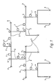
- Figure 1 is a schematic diagram of the layout of a sortation system of the invention
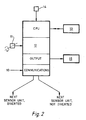
- Figure 2 is a shematic block diagram of the elements within a sensor unit for use in the present invention
- Figure 3 is a schematic diagram of a collation system of the invention.
- the system comprises a series of sensor units 1 mounted adjacent a conveyor system comprising a series of conveyors 2 laid out in a branching path network serving the various storage bins or other destinations 3 to which articles are to be fed.
- the conveyor system can be of a wide range of types, for example endless belt or mesh conveyors which carry the articles upon their upper face; chain or other conveyors in which the articles are suspended from the conveyor; or pneumatic or other systems in which the article is carried in a fluent medium.
- endless belt or mesh conveyors which carry the articles upon their upper face
- chain or other conveyors in which the articles are suspended from the conveyor
- pneumatic or other systems in which the article is carried in a fluent medium.
- the sensor units 1 can be mounted immediately adjacent the conveyor they serve so that the unit detects the passage of an article on the conveyor by a detection device, for example using a micro switch or a flip flop switch which is actuated by contact with the article.
- the detection device can detect the passage of the article by means of a magnetically operated proximity switch, eg. a Hall effect sensing device, by thermal means or by the interruption of a light beam.
- the sensor unit can be mounted some distance away from the conveyor.
- a non-contact sensing means will be used and the sensor unit will be mounted to the side of the conveyor.
- the sensing device is actuated by the leading edge of the article as it passes the sensor unit.
- the detection device in the sensor unit detects the passage of an article using contact or non-contact means as described above. This detection need not occur as the article actually passes the sensor unit, but the presence of an article could be detected by a detection device located some distance upstream of the sensor unit, as when the leading edge of the article cuts a light beam located upstream of the sensor unit.
- passage of the article is therefore used herein to denote the fact that an article has passed through the area of the conveyor path monitored by the sensor unit.
- the conveyor system is provided with means 4 for deflecting an article from one conveyor to another or off a conveyor into a storage bin or other destination.
- the deflection means will be a gate or a pusher mechanism which moves the article by physical contact therewith.
- air blasts or other non-contact means to deflect articles.
- the operation of the deflection means 4 is controlled by a sensor unit 1 which is usually that sensor immediately upstream of the deflection means.
- another sensor unit 1 is interposed between the deflection means 4 and the sensor unit 1 controlling it, as when the intermediate sensor unit is used solely to detect reject articles and actuates means for rejecting those from the system before they reach the deflection means.
- the conveyor system comprises a series of conveyors forming a branching network of paths along which articles travel to reach storage bins or other destinations located along those paths or at the ends thereof, each branch in the path having a deflection means operatively associated therewith and each destination not located at the end of a path having a deflection means associated therewith, each deflection means being controlled by a sensor unit located upstream thereof, each sensor unit being connected in series with the sensor unit upstream thereof to form a branching string of the sensor units extending from a single sensor unit at the entry point to the conveyor system.
- a total conveyor system may consist of more than one of such basic systems radiating from a central entry point or operating in cascade with one another, for example where the number of destinations in the total system exceeds the number which can be handled by the sensor units used, re-entry of destination information occuring when an article transfers from one basic system to the next.
- the system can have an initial collation system receiving articles from a number of sources and feeding a collated single stream of articles to the input of a distribution system as described above.
- the sensor units carry out several functions as an article passes them. Firstly, the sensor unit detects the passage of an article and transmits that fact to the succeeding sensor unit in the series. This initiates the travel duration monitoring of the sensor.
- the sensor unit contains information about the expected duration of the travel of the article from the preceding sensor unit which it can either hold in its own memory or this information can be sent to it from the preceding sensor unit.
- the sensor unit also has means, for example a timer/counter, for establishing the actual travel duration and for comparing that with the estimated duration to determine whether the two are the same or within an acceptable discrepancy as described below and thus whether an article observed by the sensor unit is a valid article or not. That is, does the article pass the sensor unit at the expected travel duration or does it pass at some point sufficiently outside the expected duration for it not to be the article signalled by the preceding sensor unit.
- the information about the expected travel duration is based on the time taken for an article to travel between the two sensor units and this is established during setting up of the system initially.
- the duration can be expressed as the distance between the two sensor units and this is measured, for example, by means of a shaft encoder operating on a drive shaft of the conveyor to generate pulsed signals corresponding to a unit distance travelled by the conveyor; or a combination of the two.
- the duration can be expressed as a time or distance interval between articles leaving the preceding sensor unit so that the subsequent sensor unit monitors the intervals between successive articles reaching it and rejects those which do not fall within the interval signalled from the preceding sensor unit.
- the travel duration monitoring means can be selected from a wide range of means conventionally used in the electronics industry, for example a clock timer or a counter. It is also preferred that such means should be variable so that some discrepancy in the observed as opposed to the expected duration can be allowed for. Thus, articles which are snagged on an obstruction or which are otherwise displaced a minor amount on the conveyor are accepted and not treated as reject articles merely because their travel duration is not exactly the same as that expected. The optimum value for this discrepancy can be readily determined by simple trial and error.
- the sensor unit also incorporates means for interpreting information concerning the identity and/or destination of the article which is fed to it from the preceding sensor unit.
- this information is held as a list of identities and/or destinations in a memory unit which is scanned to compare the incoming data with the list held, each sensor unit in thr system having a numerical or other machine handleable code to identify the destination it serves in a distribution (sortation) system or the identity of the articles derived from the source that sensor unit serves in a collation system.
- sortation distribution
- a single list of the identities and/or destinations downstream of the sensor unit will be held in the memory and a direct comparison with the incoming destination data can be carried out.
- the destinations will be held in two or more lists corresponding to whether the gate/divertor is to be actuated or not.
- the incoming data will be compared to the lists to determine which list they fall in and thus whether the gate/actuator is to actuated or not.
- the sensor unit incorporate a microprocessor and memory unit to enable it to carry out the functions required of it and these can be of any suitable form and method of operation. It is also preferred that the sensor unit should be capable of handling data relating to up to 100 or more articles in transit at any one time, although this number could be chosen at will depending on the parameters of the system and the capabilities of the hardware used. It is also preferred that the memory of the sensor unit should operate on an overflow, or first in first out, basis whereby information moves progressively through the memory as further information is fed into the memory until the oldest information is discarded once the memory is full. Additionally or alternatively, old information can be discarded after a predetermined time period has elapsed. Such types of memory for electronic data handling are readily available commercially in integrated circuit form. However, it is also possible to control the discarding of information from the memory by software control.
- the information transmitted between sensor units is preferably transmitted in the form of electrical signals along wires connecting the sensor units in series.
- the information could be transmitted by other means, for example accoustically, optically either as a modulated light beam or along fibres, or by radio or other electromagnetic radiation.
- the transmitting means within or associated with each sensor unit can thus take a number of forms, but is preferably in the form of an output amplification device which transmits electrical signals to the next sensor unit in the series through interconnecting wires.
- the first sensor unit in a system will incorporate means for entering the identity and/or destination information thereinto for onward transmission to the succeeding unit in the series.
- the information can be entered manually via a suitable keyboard, can be entered by providing indicia on the article, eg. bar codes or magnetic strips, which are scanned by the first sensor unit, or can be fed to the first sensor unit from a sensor unit on a collation system feeding articles to the system.
- the sensor units can incorporate means for giving a permanent record of the articles handled by that unit, for example a printer or the like. It is also preferred that the sensor units incorporate means whereby they can send information to the preceding sensor unit in the series during the setting up of the transport mechanism, as described below. This is conveniently achieved by suitable programming of the microprocessor within the sensor unit in known manner.
- the components used to construct the sensor unit and the transport mechanism of the invention can be of conventional design and construction. However, the necessary operating instructions can be programmed into the microprocessor within the sensor unit to provide an intelligent unit programmed to operate the method of the invention.
- FIG. 2 A specific example of a sensor unit suitable for use in the system of the invention is shown diagrammatically in Figure 2 and comprises a data input port 10, eg. of the RS 232 or 422 type, to receive a communications wire from a preceding unit.
- the port 10 is connected to a microprocessor 12, eg. of the Zilog 80 type, which controls the operation of the sensor unit.
- a shaft encoder 11 feeds signals into a timer/counter 12 integrated with the central processor unit (CPU) of microprocessor 12.
- CPU central processor unit
- the unit controls a branch in the conveyor path
- the sensor unit scans the lists to see which list the destination lies on. This will then tell the unit how the deflection means is to be operated, eg. gate open or closed.
- a collation system of the invention is shown diagrammatically in Figure 3 and comprises a main conveyor 20 which carries articles fed to it from side conveyors 21, for example different products from different production lines.
- the flow of articles from each side conveyor onto conveyor 20 is controlled by a gate 22 operated by a sensor unit 23.
- This sensor is located on the main conveyor upstream of the junction between the side and main conveyors.
- the sensor unit is essentially the same as that shown in Figure 2 and has an article detection means 24 monitoring the arrival of articles at gate 22 on the side conveyor and a second detection device 25 to monitor the arrival of articles at the sensor unit on the main conveyor.
- the sensor monitors the flow of articles along conveyor 20 and passes information to the succeeding sensor in the series along conveyor 20.
- the sensor unit also monitors the arrival of an article on side conveyor 21.
- sensor unit 23 When there is a suitable gap in the flow of articles along conveyor 20, sensor unit 23 actuates gate 22 to permit the article on conveyor 21 to move onto conveyor 20.
- the sensor unit 23 passes to the succeeding sensor unit the information of the identity of the article (which it recognises from the identity of the side conveyor) and includes this in the chain of information being passed along the series of sensor units.
- the sensor units 1 are located adjacent the conveyor system 2 they are to serve and are connected in series back to the first unit 1 at the entry point to the conveyor system 2.
- the sensor units 1 are then put into a reporting mode whereby each sensor unit reports upstream to its preceding unit and gives the identity of the destinations which are downstream of it.
- a sensor unit operates a branch in the conveyor, it will receive information from each branch which it stores on separate sections, or lists, of its memory. However, it reports a single list of all destinations which are downstream of it to the preceding sensor unit. This process is repeated until the whole list of destinations is reported to and memorised by the first sensor unit.
- the travel durations to be expected between sensor units for example the count/timer values to be observed, between individual sensors can be determined by putting the system into a "teach" mode and running articles through it so that the system can measure and store the correct value.
- this value could be determined theoretically from the geometry of the system and entered into each sensor unit or it can be measured and adjusted by running a series of articles through the system and entering the values found in practice to be most suited to the system into each sensor unit.
- the optimum 'window' for those values can also be determined by simple trial and error tests.
- information concerning the destination and/or identity of an article passing the first sensor unit at the entry to the transport mechanism is fed to the sensor unit, for example by being manually keyed into the sensor unit or by the sensor unit scanning markings on the article optically or magnetically.
- This information is fed on to the next sensor unit along the path the article is to follow together with a signal indicating when the article departs from the previous sensor unit to initiate the count/timer in the succeeding sensor unit and information about the expected duration of travel between the sensor units, where this is not already held in the memory of that next sensor unit.
- the next sensor unit detects when an article reaches it, verifies that the actual duration of travel from the preceding sensor unit complies with the expected duration of travel, thus verifying that the article is the one expected and that the identity and/or destination information relates to it.
- the next sensor unit serves the same length of conveyor or a conveyor which is moving at substantially the same speed as that served by its preceding sensor unit, the count/timer signal generation rate will be consistent with that of the sensor unit from which it derives its information.
- the conveyors are moving at different speeds, as is often the case with secondary conveyors fed from a main conveyor, the signal generation rate will be different and may introduce sufficient errors to be unacceptable. In such a case it is desirable that the start of the count/timer signal generation be related to the actuation of the deflection means serving the second conveyor.
- the second sensor unit can not verify the travel duration of the article, for example where the article has been snagged on an obstruction or where the article has been placed on the conveyor between the sensor units, the second sensor unit will treat the article as a reject. It can then either cause the article to be ejected from the system immediately, or it can assign the article a destination coding corresponding to a reject destination. The article will then be treated as a valid article and information concerning it passed down the series of sensor units to ensure that it is directed into a reject destination.
- the verification of a valid article described above can be carried out in response to a trigger signal from the article detection device when an article actuates it, in which case the sensor unit scans its memory and count/timer to establish whether the trigger signal corresponds to a valid signal. Alternatively, the sensor unit can remain quiescent until its count/timer shows that an article should be triggering the detection device and it then scans to see whether such a trigger signal occurs.
- the sensor unit establishes the identity and/or destination of the article from its memory and actuates the deflection means it controls in the appropriate manner.
- the sensor unit will send an electrical signal to actuate the deflection means.
- other means for actuating the deflection means can be used.
- the deflection means will usually take a finite time to operate, will be located some distance downstream of the sensor unit and a number of articles will be in transit between the sensor unit and the deflection means. It will usually therefore be necessary to incorporate a suitable time delay between the sensor establishing the validity of signal and actuating the deflection means so as to ensure that the deflection means acts upon the correct article.
- the deflection means may incorporate its own counter/timer circuit so that it delays acting upon a signal from the sensor unit for the requisite time.
- the sensor unit also sends a signal to the next sensor unit identifying the intended destination of the article and intiating the count/timer of the next sensor unit.
- the system does not require major computing power at the sensor units and can be readily extended or varied merely by adding or subtracting units where desired. Since each sensor unit contains sufficient intelligence to be set up and operated individually, no re-programming of a central computer is required and the sensor units are set up by passing articles through them rather than by adjustment of the program within them.
- the system of the invention can be installed by persons not skilled in computer programming.
- the system of the invention can be applied to existing transportation mechanisms as well as being incorporated ab initio. Furthermore, since the sensor units create reject destinations for false or erroneous articles, these do not disrupt the synchrony of information relating to other articles and the system is self correcting. The ability to adjust independently the travel duration for each sensor and the discrepancy in the travel duration which it will accept, enables the systems of the invention to be manufactured in a standard form which is capable of use over a wide range of conditions.
Landscapes
- Engineering & Computer Science (AREA)
- Mechanical Engineering (AREA)
- Control Of Conveyors (AREA)
- Branching, Merging, And Special Transfer Between Conveyors (AREA)
Applications Claiming Priority (2)
| Application Number | Priority Date | Filing Date | Title |
|---|---|---|---|
| GB868618298A GB8618298D0 (en) | 1986-07-26 | 1986-07-26 | Transport ordering system |
| GB8618298 | 1986-07-26 |
Publications (2)
| Publication Number | Publication Date |
|---|---|
| EP0255353A2 true EP0255353A2 (fr) | 1988-02-03 |
| EP0255353A3 EP0255353A3 (fr) | 1988-10-12 |
Family
ID=10601758
Family Applications (1)
| Application Number | Title | Priority Date | Filing Date |
|---|---|---|---|
| EP87306690A Withdrawn EP0255353A3 (fr) | 1986-07-26 | 1987-07-29 | Système de commande pour transporteurs |
Country Status (4)
| Country | Link |
|---|---|
| EP (1) | EP0255353A3 (fr) |
| JP (1) | JPS63262327A (fr) |
| AU (1) | AU7608887A (fr) |
| GB (1) | GB8618298D0 (fr) |
Cited By (5)
| Publication number | Priority date | Publication date | Assignee | Title |
|---|---|---|---|---|
| EP0330260A1 (fr) * | 1988-02-15 | 1989-08-30 | Staalkat B.V. | Procédé et dispositif de tri et d'éjection d'articles |
| EP0376402A1 (fr) * | 1988-12-29 | 1990-07-04 | Geerts-Veen, Catharina Afien | Elément intermédiaire ou membre de signalisation |
| EP0721807A3 (fr) * | 1995-01-11 | 1998-02-04 | MANNESMANN Aktiengesellschaft | Commande pour installation de manutention |
| WO2002074455A3 (fr) * | 2001-03-20 | 2003-02-27 | Lockheed Corp | Objet et procede permettant d'acceder a des articles a partir d'une connaissance sure de leur position |
| CN106076860A (zh) * | 2016-08-19 | 2016-11-09 | 吴秋 | 多级分选系统 |
Family Cites Families (5)
| Publication number | Priority date | Publication date | Assignee | Title |
|---|---|---|---|---|
| US3214003A (en) * | 1961-11-27 | 1965-10-26 | Cutler Hammer Inc | Automatic sequencing selectable read out control for random selection for diversion of items located on a conveyor live storage loop |
| GB1094151A (en) * | 1963-02-13 | 1967-12-06 | English Electric Co Ltd | Electric control means |
| US3743090A (en) * | 1971-04-28 | 1973-07-03 | M Brown | Method and apparatus for selectively removing pre-identified articles from a conveyor system |
| FR2395080A1 (fr) * | 1977-06-21 | 1979-01-19 | Kronenbourg Brasseries | Installation pour l'identification automatique des futs |
| DE3523554A1 (de) * | 1984-08-24 | 1986-03-06 | Peter L. Ing.(grad.) 8084 Inning Ortloff | Vorrichtung zur kontaktfreien steuerung einer foerder-, sortier- und/oder verarbeitungsanlage |
-
1986
- 1986-07-26 GB GB868618298A patent/GB8618298D0/en active Pending
-
1987
- 1987-07-24 AU AU76088/87A patent/AU7608887A/en not_active Abandoned
- 1987-07-27 JP JP18748087A patent/JPS63262327A/ja active Pending
- 1987-07-29 EP EP87306690A patent/EP0255353A3/fr not_active Withdrawn
Cited By (6)
| Publication number | Priority date | Publication date | Assignee | Title |
|---|---|---|---|---|
| EP0330260A1 (fr) * | 1988-02-15 | 1989-08-30 | Staalkat B.V. | Procédé et dispositif de tri et d'éjection d'articles |
| EP0376402A1 (fr) * | 1988-12-29 | 1990-07-04 | Geerts-Veen, Catharina Afien | Elément intermédiaire ou membre de signalisation |
| EP0721807A3 (fr) * | 1995-01-11 | 1998-02-04 | MANNESMANN Aktiengesellschaft | Commande pour installation de manutention |
| WO2002074455A3 (fr) * | 2001-03-20 | 2003-02-27 | Lockheed Corp | Objet et procede permettant d'acceder a des articles a partir d'une connaissance sure de leur position |
| US6711461B2 (en) | 2001-03-20 | 2004-03-23 | Lockheed Martin Corporation | Object and method for accessing of articles for reliable knowledge of article positions |
| CN106076860A (zh) * | 2016-08-19 | 2016-11-09 | 吴秋 | 多级分选系统 |
Also Published As
| Publication number | Publication date |
|---|---|
| GB8618298D0 (en) | 1986-09-03 |
| EP0255353A3 (fr) | 1988-10-12 |
| AU7608887A (en) | 1988-01-28 |
| JPS63262327A (ja) | 1988-10-28 |
Similar Documents
| Publication | Publication Date | Title |
|---|---|---|
| US6466828B1 (en) | Device controller with intracontroller communication capability, conveying system using such controllers for controlling conveying sections and methods related thereto | |
| CN114423532B (zh) | 模块化包裹分拣系统 | |
| US11912509B2 (en) | Modular package sorting system | |
| CA1133610A (fr) | Transporteur a postes de tri | |
| US6878896B2 (en) | Synchronous semi-automatic parallel sorting | |
| US6762382B1 (en) | Track-type sortation system | |
| US5186336A (en) | Product sorting apparatus | |
| EP0310411B1 (fr) | Procédé et appareil pour séparer des articles transportés par un système de transport | |
| US5165515A (en) | Segmented pusher control for conveying system | |
| WO1998022857A9 (fr) | Procede permettant de commander des appareils, organe de commande d'appareils et systeme d'acheminement | |
| AU615683B2 (en) | Process and plant for sorting items in an open path system | |
| US6419782B1 (en) | Bar code overlabeling system | |
| US5325972A (en) | Method of controlling sorting systems, and a sorting system thus controlled | |
| US20030155213A1 (en) | Bi-directional package divert mechanism and method of use | |
| JP2025520631A (ja) | イントラロジスティックコンベア装置 | |
| EP0130810B1 (fr) | Système de tri à convoyeur | |
| US11167935B2 (en) | Transportation path diverter | |
| EP0255353A2 (fr) | Système de commande pour transporteurs | |
| US4373185A (en) | Tracking in a distribution system | |
| US20020038753A1 (en) | Apparatus and method for controlling segmented conveyor system | |
| CN117181611A (zh) | 直线窄带分拣系统的窄带小车与包裹的匹配方法、系统及控制装置 | |
| KR20000009657A (ko) | 단일 라인 다품종 소량 생산 시스템 | |
| US2984349A (en) | Mail handling apparatus | |
| US20240338654A1 (en) | Loading method and loading station for conveying containers | |
| US12252354B2 (en) | Method for removing piece goods from a conveyor, blowoff device and sorting system |
Legal Events
| Date | Code | Title | Description |
|---|---|---|---|
| PUAI | Public reference made under article 153(3) epc to a published international application that has entered the european phase |
Free format text: ORIGINAL CODE: 0009012 |
|
| AK | Designated contracting states |
Kind code of ref document: A2 Designated state(s): AT BE CH DE ES FR GB GR IT LI NL SE |
|
| PUAL | Search report despatched |
Free format text: ORIGINAL CODE: 0009013 |
|
| AK | Designated contracting states |
Kind code of ref document: A3 Designated state(s): AT BE CH DE ES FR GB GR IT LI NL SE |
|
| STAA | Information on the status of an ep patent application or granted ep patent |
Free format text: STATUS: THE APPLICATION IS DEEMED TO BE WITHDRAWN |
|
| 18D | Application deemed to be withdrawn |
Effective date: 19890413 |
|
| RIN1 | Information on inventor provided before grant (corrected) |
Inventor name: ASHLEY, MICHAEL DAVIDSILVERGLADE |