EP0255365A2 - Sicherheitsverschluss - Google Patents
Sicherheitsverschluss Download PDFInfo
- Publication number
- EP0255365A2 EP0255365A2 EP87306714A EP87306714A EP0255365A2 EP 0255365 A2 EP0255365 A2 EP 0255365A2 EP 87306714 A EP87306714 A EP 87306714A EP 87306714 A EP87306714 A EP 87306714A EP 0255365 A2 EP0255365 A2 EP 0255365A2
- Authority
- EP
- European Patent Office
- Prior art keywords
- seal member
- seal
- sliding
- channel portion
- peg
- Prior art date
- Legal status (The legal status is an assumption and is not a legal conclusion. Google has not performed a legal analysis and makes no representation as to the accuracy of the status listed.)
- Granted
Links
Images



Classifications
-
- B—PERFORMING OPERATIONS; TRANSPORTING
- B65—CONVEYING; PACKING; STORING; HANDLING THIN OR FILAMENTARY MATERIAL
- B65D—CONTAINERS FOR STORAGE OR TRANSPORT OF ARTICLES OR MATERIALS, e.g. BAGS, BARRELS, BOTTLES, BOXES, CANS, CARTONS, CRATES, DRUMS, JARS, TANKS, HOPPERS, FORWARDING CONTAINERS; ACCESSORIES, CLOSURES, OR FITTINGS THEREFOR; PACKAGING ELEMENTS; PACKAGES
- B65D55/00—Accessories for container closures not otherwise provided for
- B65D55/02—Locking devices; Means for discouraging or indicating unauthorised opening or removal of closure
Definitions
- This invention relates to a tamper-evident seal assembly for use with a locking mechanism. It is particularly suited for sealing a locking mechanism on lids of boxes or on doors, but other applications are also possible.
- Tamper-evident seals are generally known, their purpose being to indicate when any unauthorised attempt has been made to interfere with them. Seals previously used for securing items such as the lids of boxes have generally incorporated in their design some feature such as an arrowhead or barb. To provide tamper-evident properties, it is necessary for mating parts which engage the barbs to be within an enclosed housing. With such a design, it follows that there will be a point of transition between the outside of the housing, where the seal is on view and accessible, and the inside where the seal is hidden and inaccessible. At this transition point, it is theoretically possible for a seal to be cut through, thereby allowing the sealing device to be opened, followed by repairing the seal by either welding or use of adhesives. Since such a repair would be located in line with the mouth of the housing, it is possible for it to be overlooked at the time of inspection prior to opening of the seal by authorised personnel.
- a further feature of many seals at present used for securing lids of boxes is that they include fasteners (such as toggle fasteners which require the use of wire or string on which the ultimate seal is fixed.
- fasteners such as toggle fasteners which require the use of wire or string on which the ultimate seal is fixed.
- the use of such ancillary tying media is undesirable in the security seal field.
- An object of the present invention is to provide a tamper-evident seal for use such as the securing of lids or doors, without the disadvantages referred to above.
- the present invention accordingly provides a tamper-evident seal assembly for use with a locking mechanism, the locking mechanism including a sliding member which is slidable between a locked position and an unlocked position, said sliding member having a transversely projecting peg portion, the seal assembly comprising a channel portion defining in its base a longitudinally aligned slot through which the peg portion can protrude, and a disposable breakable seal member which is longitudinally slidable in the channel portion, the seal member having means for engagement with the projecting peg portion, such that, in the unlocked position, the seal member can be placed in the channel portion and in engagement with the peg portion, the seal member then being slidable in the channel portion and engagement between the seal member and the peg portion causing corresponding sliding of the sliding member to its locked position, in which position retaining parts of the channel portion prevent lifting of the seal member, whilst the engagement between the seal member and the peg portion prevents sliding withdrawal of the seal member, whereby the locking mechanism is held in the locked position until the
- the tamper-evident seal assembly according to the invention can be used with any kind of locking mechanism which includes a sliding member slidable between a locked position and an unlocked position, the sliding member having an upstanding peg or handle portion.
- a locking mechanism which includes a sliding member slidable between a locked position and an unlocked position, the sliding member having an upstanding peg or handle portion.
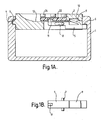
- FIGs 1A and 1B An example of such a locking mechanism, applied to the locking of the lid of a box, is shown in Figures 1A and 1B.
- the upstanding peg or handle portion has to be initially lifted to permit unlocking by retraction of the sliding member and has to be depressed to permit locking by sliding forward the sliding member.
- Figures 6A and 6B An alternative example is shown in Figures 6A and 6B in which no lifting or depressing of the sliding member peg is necessary. It should be understood that these examples are only for purposes of illustration, and the seal assembly according to the invention can be used with any kind of locking mechanism having the
- a box 1 has a lid 2.
- One edge of the lid has a projecting portion 3 capable of engaging with a corresponding channel portion 4 near the top of one inside wall of the box.
- Locking of the lid to the box is effected by a sliding bolt 5 which, in the locked position, engages beneath an overhanging portion 6 of an inside wall of the box.
- the bolt 5 has laterally extending trunnions 7 which engage for sliding and rotational movement in longitudinal slots 8 in the lid.
- the upper surface of the bolt 5 has a resilient barb 9. This is adapted to engage with a downwardly directed cut-out portion 10 of the lid for retention of the bolt in the locked position.
- An end of the bolt remote from the locking portion has an upwardly projecting peg portion 11 which projects through an opening in part of the top surface 12 of the lid.
- the barb 9 is resiliently pressed by the underside portion of the lid against the top surface of the bolt, until it meets the retaining opening 10, at which point the barb resiliently swings out from the bolt to engage in the opening 10 and thereby retain the bolt in the locked position.
- the purpose of the tamper-evident seal assembly according to the invention is to retain the bolt 5 in its locked position in such a way that it can only be unlocked by breakage of a seal member. Such breakage is only to be carried out by authorised personnel. The bolt cannot be unlocked without breakage of the seal, and any breakage and subsequent repair of the seal member would be immediately evident on inspection before authorised opening.
- the seal assembly comprises a channel portion 20 which is integral with or permanently fixed to the upper surface 12 of the lid 2.
- a longitudinally aligned slot 21 through which projects the peg portion 11 of the bolt 5.
- a seal member 22 is of substantially rectangular plate shape and is adapted to slide longitudinally in the channel member.
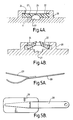
- the seal member has in its underside (see Figure 3A) a socket 23 which is adapted to receive the protruding peg portion 11 when the seal member is placed downwardly into the channel portion.
- the socket 23 is dimensioned such that when the seal member 22 rests on the base of the channel portion 20, it depresses the peg portion 11 to the extent necessary to rotate the bolt 5 anti-clockwise until it is substantially horizontal. At this point, the peg portion 11 still protrudes through the slot 21 to a sufficient extent for it to be engaged within the socket 23.
- forward sliding of the seal member 22 in the channel portion 20 causes the bolt 5 to slide forwardly to its locked position. The path taken by the seal member 22 on locking is thus initially downward into the channel portion 20, and then forward, as shown in Figures 3A and 3B.
- the opposing inner longitudinal faces of the channel portion 20 have castellated projecting substantially semi-circular retaining parts 24.
- the seal member 22 has on its opposing longitudinal edges correspondingly spaced and shaped indentations 25.
- the socket 23 is positioned such that it fits over the protruding peg portion 11 at this point. Subsequent sliding forward of the seal member 22 causes the retaining parts 24 and indentations 25 to become out of register, the retaining parts 24 then overlapping the tops of the longitudinal edge portions of the seal member.
- the seal member To facilitate breakage of the seal member, it has a central longitudinal portion 26 which is relatively thin, compared with the longitudinal outer portions.
- the socket 23 is positioned in the relatively thick outer longitudinal portion, on one side of the central portion.
- a "spare" socket may be positioned in the opposite side portion, so that the seal member 22 is symmetrical and can be positioned facing either longitudinal direction in the channel portion.
- the base of the channel portion has a central undercut part 27 extending from about half way along and gradually sloping upwardly to the top surface at one end. This facilitates the insertion beneath the seal member 22 of a seal breaking tool or lever 28. This is introduced by authorised personnel when the seal member is to be broken.
- the tool is introduced beneath the seal member and then levered upwardly to break the seal member along its thin central portion 26, as shown in Figure 4B.
- the tool has an upper protective screen 29 which covers the top of the seal member at the time of breakage, to prevent accidental injury from parts of the broken seal member flying upwards.
- the peg member 11 can then be lifted and used to slide the bolt backwards to the unlocked position. When the lid is to be locked again, a fresh seal member will have to be used.
- the seal member 22 is preferably made of relatively rigid plastics material so as to exhibit easily discernible evidence if it is damaged. The features of engagement of the seal member and the channel portion are all clearly visible, thereby affording no opportunity for tampering which could be hidden.
- the top surface of the seal member is a simple flat shape, and ideal for presentation of printed information and identification such as an individual bar code or sequential number. It will be noted that the non-expendable parts of the seal assembly are conveniently housed within an enclosure, and so ancillary tying media such as string or wire are necessary.
- Figures 6A and 6B show a box 40 with a lid 41.
- One edge of the lid has a projecting portion 42 capable of engaging with a channel portion 43 near the top of the box wall.
- Locking of the lid to the box is effected by a sliding bolt 44 which in the locked position engages beneath an overhanging portion 45 of an inside wall of the box.
- the bolt 44 has a peg or handle 46 projecting through a slot 47 in the lid permitting its operation by hand.
- a sliding member 50 has a peg 51 which engages with a socket in the underside of the seal 48. This sliding member 50 is provided at its rearward end 55 with a resilient portion 52.
- the seal is inserted in its channel and located on the peg 51. Forward movement of the seal causes the member 50 to slide in a direction lateral to the bolt 44 but closely adjacent to it until the resilient portion 52 springs into engagement against the lip 53 of the bolt 44.
Landscapes
- Engineering & Computer Science (AREA)
- Mechanical Engineering (AREA)
- Closures For Containers (AREA)
- Sealing Battery Cases Or Jackets (AREA)
- Wrappers (AREA)
- Refinement Of Pig-Iron, Manufacture Of Cast Iron, And Steel Manufacture Other Than In Revolving Furnaces (AREA)
- Absorbent Articles And Supports Therefor (AREA)
- Materials For Medical Uses (AREA)
- Cartons (AREA)
Priority Applications (1)
| Application Number | Priority Date | Filing Date | Title |
|---|---|---|---|
| AT87306714T ATE87348T1 (de) | 1986-07-29 | 1987-07-29 | Sicherheitsverschluss. |
Applications Claiming Priority (2)
| Application Number | Priority Date | Filing Date | Title |
|---|---|---|---|
| GB868618468A GB8618468D0 (en) | 1986-07-29 | 1986-07-29 | Tamper-evident seal assembly |
| GB8618468 | 1986-07-29 |
Publications (3)
| Publication Number | Publication Date |
|---|---|
| EP0255365A2 true EP0255365A2 (de) | 1988-02-03 |
| EP0255365A3 EP0255365A3 (en) | 1989-04-26 |
| EP0255365B1 EP0255365B1 (de) | 1993-03-24 |
Family
ID=10601860
Family Applications (1)
| Application Number | Title | Priority Date | Filing Date |
|---|---|---|---|
| EP87306714A Expired - Lifetime EP0255365B1 (de) | 1986-07-29 | 1987-07-29 | Sicherheitsverschluss |
Country Status (5)
| Country | Link |
|---|---|
| EP (1) | EP0255365B1 (de) |
| AT (1) | ATE87348T1 (de) |
| DE (1) | DE3784979T2 (de) |
| ES (1) | ES2038990T3 (de) |
| GB (1) | GB8618468D0 (de) |
Families Citing this family (1)
| Publication number | Priority date | Publication date | Assignee | Title |
|---|---|---|---|---|
| RU2136831C1 (ru) * | 1998-03-26 | 1999-09-10 | Болдырев Александр Александрович | Способ стопорения запирающих элементов |
Family Cites Families (2)
| Publication number | Priority date | Publication date | Assignee | Title |
|---|---|---|---|---|
| US1367647A (en) * | 1920-06-18 | 1921-02-08 | Edwin C Washburn | Sealed padlock |
| US1587651A (en) * | 1925-07-23 | 1926-06-08 | Presley B Johnson | Lock seal |
-
1986
- 1986-07-29 GB GB868618468A patent/GB8618468D0/en active Pending
-
1987
- 1987-07-29 AT AT87306714T patent/ATE87348T1/de not_active IP Right Cessation
- 1987-07-29 ES ES198787306714T patent/ES2038990T3/es not_active Expired - Lifetime
- 1987-07-29 DE DE8787306714T patent/DE3784979T2/de not_active Expired - Fee Related
- 1987-07-29 EP EP87306714A patent/EP0255365B1/de not_active Expired - Lifetime
Also Published As
| Publication number | Publication date |
|---|---|
| DE3784979D1 (de) | 1993-04-29 |
| GB8618468D0 (en) | 1986-09-03 |
| ES2038990T3 (es) | 1993-08-16 |
| ATE87348T1 (de) | 1993-04-15 |
| EP0255365B1 (de) | 1993-03-24 |
| EP0255365A3 (en) | 1989-04-26 |
| DE3784979T2 (de) | 1993-07-01 |
Similar Documents
| Publication | Publication Date | Title |
|---|---|---|
| US4001919A (en) | Seal | |
| US3955842A (en) | Locking device | |
| US4331257A (en) | Closure for a container having additional securing means | |
| US4602405A (en) | Containers provided with sealable sliding fasteners | |
| EP0223760A1 (de) | Verschluss für ein eine Compact-Disc oder eine Bandkassette enthaltendes Behältnis | |
| CA2131531A1 (en) | Security package for compact discs | |
| US6918620B2 (en) | Locking device | |
| JP2003517617A (ja) | 安全タグ装置 | |
| EP0255365B1 (de) | Sicherheitsverschluss | |
| EP0043726B1 (de) | Verriegelbare Befestigungsvorrichtung | |
| US3147607A (en) | Safety padlock | |
| EP2063733B1 (de) | Originalitätssicherungsvorrichtung | |
| WO2001031152A1 (en) | Opener for a magnetic latch in an anti-theft device for cassettes | |
| US10913576B2 (en) | Tamper evident locking device | |
| GB2163392A (en) | Security seal | |
| US20070040395A1 (en) | Padlock seal | |
| US20040173614A1 (en) | Locking mechanism on a holding device or a package | |
| US20110138866A1 (en) | Access identification assembly and method of using same | |
| JPS62241187A (ja) | コンパクトディスク又はテープカセットの収納箱の封印装置 | |
| EP1076327A2 (de) | Sicherheitsbehälter | |
| US234725A (en) | Packing box or case | |
| WO1996012654A1 (en) | Tamper-proof cargo seal | |
| GB2420743A (en) | Tamper resistant sealing device | |
| EP1118538A2 (de) | Druckbetätigte Verriegelungsvorrichtung | |
| US855086A (en) | Seal-lock. |
Legal Events
| Date | Code | Title | Description |
|---|---|---|---|
| PUAI | Public reference made under article 153(3) epc to a published international application that has entered the european phase |
Free format text: ORIGINAL CODE: 0009012 |
|
| AK | Designated contracting states |
Kind code of ref document: A2 Designated state(s): AT BE CH DE ES FR GB GR IT LI LU NL SE |
|
| PUAL | Search report despatched |
Free format text: ORIGINAL CODE: 0009013 |
|
| RHK1 | Main classification (correction) |
Ipc: E05B 39/02 |
|
| AK | Designated contracting states |
Kind code of ref document: A3 Designated state(s): AT BE CH DE ES FR GB GR IT LI LU NL SE |
|
| RAP3 | Party data changed (applicant data changed or rights of an application transferred) |
Owner name: ENVOPAK GROUP LIMITED |
|
| 17P | Request for examination filed |
Effective date: 19890905 |
|
| 17Q | First examination report despatched |
Effective date: 19910211 |
|
| GRAA | (expected) grant |
Free format text: ORIGINAL CODE: 0009210 |
|
| AK | Designated contracting states |
Kind code of ref document: B1 Designated state(s): AT BE CH DE ES FR GB GR IT LI LU NL SE |
|
| PG25 | Lapsed in a contracting state [announced via postgrant information from national office to epo] |
Ref country code: IT Free format text: LAPSE BECAUSE OF FAILURE TO SUBMIT A TRANSLATION OF THE DESCRIPTION OR TO PAY THE FEE WITHIN THE PRE;WARNING: LAPSES OF ITALIAN PATENTS WITH EFFECTIVE DATE BEFORE 2007 MAY HAVE OCCURRED AT ANY TIME BEFORE 2007. THE CORRECT EFFECTIVE DATE MAY BE DIFFERENT FROM THE ONE RECORDED.SCRIBED TIME-LIMIT Effective date: 19930324 Ref country code: SE Effective date: 19930324 Ref country code: NL Effective date: 19930324 Ref country code: AT Effective date: 19930324 Ref country code: CH Effective date: 19930324 Ref country code: BE Effective date: 19930324 Ref country code: LI Effective date: 19930324 Ref country code: GR Free format text: LAPSE BECAUSE OF FAILURE TO SUBMIT A TRANSLATION OF THE DESCRIPTION OR TO PAY THE FEE WITHIN THE PRESCRIBED TIME-LIMIT Effective date: 19930324 |
|
| REF | Corresponds to: |
Ref document number: 87348 Country of ref document: AT Date of ref document: 19930415 Kind code of ref document: T |
|
| REF | Corresponds to: |
Ref document number: 3784979 Country of ref document: DE Date of ref document: 19930429 |
|
| ET | Fr: translation filed | ||
| REG | Reference to a national code |
Ref country code: CH Ref legal event code: PL |
|
| PG25 | Lapsed in a contracting state [announced via postgrant information from national office to epo] |
Ref country code: LU Free format text: LAPSE BECAUSE OF NON-PAYMENT OF DUE FEES Effective date: 19930731 |
|
| REG | Reference to a national code |
Ref country code: ES Ref legal event code: FG2A Ref document number: 2038990 Country of ref document: ES Kind code of ref document: T3 |
|
| NLV1 | Nl: lapsed or annulled due to failure to fulfill the requirements of art. 29p and 29m of the patents act | ||
| PLBE | No opposition filed within time limit |
Free format text: ORIGINAL CODE: 0009261 |
|
| STAA | Information on the status of an ep patent application or granted ep patent |
Free format text: STATUS: NO OPPOSITION FILED WITHIN TIME LIMIT |
|
| 26N | No opposition filed | ||
| PGFP | Annual fee paid to national office [announced via postgrant information from national office to epo] |
Ref country code: FR Payment date: 19940711 Year of fee payment: 8 |
|
| PGFP | Annual fee paid to national office [announced via postgrant information from national office to epo] |
Ref country code: DE Payment date: 19940721 Year of fee payment: 8 |
|
| PGFP | Annual fee paid to national office [announced via postgrant information from national office to epo] |
Ref country code: ES Payment date: 19940730 Year of fee payment: 8 |
|
| PG25 | Lapsed in a contracting state [announced via postgrant information from national office to epo] |
Ref country code: ES Free format text: LAPSE BECAUSE OF NON-PAYMENT OF DUE FEES Effective date: 19950730 |
|
| PG25 | Lapsed in a contracting state [announced via postgrant information from national office to epo] |
Ref country code: DE Effective date: 19960402 |
|
| PG25 | Lapsed in a contracting state [announced via postgrant information from national office to epo] |
Ref country code: FR Effective date: 19960430 |
|
| REG | Reference to a national code |
Ref country code: FR Ref legal event code: ST |
|
| REG | Reference to a national code |
Ref country code: FR Ref legal event code: ST |
|
| REG | Reference to a national code |
Ref country code: FR Ref legal event code: ST |
|
| PGFP | Annual fee paid to national office [announced via postgrant information from national office to epo] |
Ref country code: GB Payment date: 19970721 Year of fee payment: 11 |
|
| PG25 | Lapsed in a contracting state [announced via postgrant information from national office to epo] |
Ref country code: GB Free format text: LAPSE BECAUSE OF NON-PAYMENT OF DUE FEES Effective date: 19980729 |
|
| GBPC | Gb: european patent ceased through non-payment of renewal fee |
Effective date: 19980729 |
|
| REG | Reference to a national code |
Ref country code: ES Ref legal event code: FD2A Effective date: 19960810 |