EP0255372A1 - Lecteur de carte magnétique - Google Patents
Lecteur de carte magnétique Download PDFInfo
- Publication number
- EP0255372A1 EP0255372A1 EP87306726A EP87306726A EP0255372A1 EP 0255372 A1 EP0255372 A1 EP 0255372A1 EP 87306726 A EP87306726 A EP 87306726A EP 87306726 A EP87306726 A EP 87306726A EP 0255372 A1 EP0255372 A1 EP 0255372A1
- Authority
- EP
- European Patent Office
- Prior art keywords
- magnetic
- card reader
- magnetic elements
- elements
- assembly
- Prior art date
- Legal status (The legal status is an assumption and is not a legal conclusion. Google has not performed a legal analysis and makes no representation as to the accuracy of the status listed.)
- Granted
Links
Images

Classifications
-
- G—PHYSICS
- G06—COMPUTING OR CALCULATING; COUNTING
- G06K—GRAPHICAL DATA READING; PRESENTATION OF DATA; RECORD CARRIERS; HANDLING RECORD CARRIERS
- G06K7/00—Methods or arrangements for sensing record carriers, e.g. for reading patterns
- G06K7/08—Methods or arrangements for sensing record carriers, e.g. for reading patterns by means detecting the change of an electrostatic or magnetic field, e.g. by detecting change of capacitance between electrodes
- G06K7/082—Methods or arrangements for sensing record carriers, e.g. for reading patterns by means detecting the change of an electrostatic or magnetic field, e.g. by detecting change of capacitance between electrodes using inductive or magnetic sensors
- G06K7/087—Methods or arrangements for sensing record carriers, e.g. for reading patterns by means detecting the change of an electrostatic or magnetic field, e.g. by detecting change of capacitance between electrodes using inductive or magnetic sensors flux-sensitive, e.g. magnetic, detectors
- G06K7/088—Methods or arrangements for sensing record carriers, e.g. for reading patterns by means detecting the change of an electrostatic or magnetic field, e.g. by detecting change of capacitance between electrodes using inductive or magnetic sensors flux-sensitive, e.g. magnetic, detectors using magneto-sensitive switches, e.g. reed-switches
-
- G—PHYSICS
- G07—CHECKING-DEVICES
- G07C—TIME OR ATTENDANCE REGISTERS; REGISTERING OR INDICATING THE WORKING OF MACHINES; GENERATING RANDOM NUMBERS; VOTING OR LOTTERY APPARATUS; ARRANGEMENTS, SYSTEMS OR APPARATUS FOR CHECKING NOT PROVIDED FOR ELSEWHERE
- G07C9/00—Individual registration on entry or exit
- G07C9/00174—Electronically operated locks; Circuits therefor; Nonmechanical keys therefor, e.g. passive or active electrical keys or other data carriers without mechanical keys
- G07C9/00658—Electronically operated locks; Circuits therefor; Nonmechanical keys therefor, e.g. passive or active electrical keys or other data carriers without mechanical keys operated by passive electrical keys
- G07C9/00722—Electronically operated locks; Circuits therefor; Nonmechanical keys therefor, e.g. passive or active electrical keys or other data carriers without mechanical keys operated by passive electrical keys with magnetic components, e.g. magnets, magnetic strips, metallic inserts
Definitions
- This invention relates to magnetic card readers of the kind employed, for example, to release a locking device in response to the presentation of an appropriately encoded magnetic card. Whilst such readers are mainly used for this purpose, it will be appreciated that they may be used for other purposes, such as allowing access to information or the operation of equipment.
- a major disadvantage of such systems is that the magnetic card has to be inserted into a slot for this purpose, and this makes the lockset prone to vandalism, e.g. by forcing objects into the slot, and also provides a route by which the lock itself may be forced.
- One object of the invention is to provide a magnetic card reader which does not require the card to be inserted into a slot.
- a further object of the invention is to provide a magnetic card reader which provides an output signal which can be utilised to operate remote equipment.
- a magnetic card reader including a housing which defines an exposed area at its surface for the reception of a magnetically encoded card in flat juxtaposition with such housing and adjacent to an assembly of magnetic elements which are arranged so as to interact with such a magnetically encoded card and thereby actuate corresponding electrical switch means.
- the housing may afford an aperture at one face thereof for the reception of the card in the plane of the aperture, the assembly of magnetic elements being arranged in register with said aperture so that when the card is located correctly in said aperture it is disposed in face-to-face relation with said assembly.
- the housing may be made of, or include a "window" of magnetically permeable material, and have an area visually defined thereon for the reception of the card, the assembly of magnetic elements being arranged in register with said area.
- the assembly of magnetic elements preferably comprises a pair of electrically conductive members and a plurality of said magnetic elements biased into positions in which each of said elements establishes an electrical connection between said conductive members.
- the two conductive members and the magnetic elements afford a continuous electric current path and can be connected in an electric circuit responsive to a predetermined condition of the card reader, the magnetic elements being movable out of contact with at least one of the conductive members by magentic interaction with the appropriately encoded magnetic card.
- the predetermined condition of the card reader would normally reflect an open-circuit condition for all of the magnetic elements but other arrangements are possible as mentioned in the following description.
- the magnetic elements are preferably biased by spring means into contact with one of said conductive members, the latter being made of a non-magnetisable material.
- the magnetic card may thus be applied directly to that conductive member (although a layer of electrically insulating material may be interposed if desired) to move the magnetic elements against the spring-bias and away from the conductive member into open-circuit conditions so as to break the current path.
- the card reader preferably has associated therewith an electronic circuit which provides an output signal indicative of said predetermined condition of the card reader only if such condition is established and maintained for a period of time which exceeds the natural resonant frequency of the magnetic element and spring combination.
- an end-of-line resistor may be associated with the card reader so that when the magnetic elements are in their open-circuit conditions the reader presents a predetermined resistance to the circuit which is responsive to the reader.
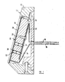
- the reader comprises a detector assembly 10 mounted within a housing 11 comprising casing 12 secured to a back plate 14 adapted for mounting on any convenient surface, for example on or adjacent to a door which is fitted with an electromagnetic lock.
- the casing 12 includes at its forward face an aperture 16 which serves to locate a magnetically coded card (not shown) in the correct face-to-face relationship with the detector assembly 10.
- the detector assembly 10 need not be recessed from the forward surface of the housing 11 a shown, but could be flush therewith, in which case appropriate markings would be provided to indicate the required position of the magnetically coded card.
- the housing 11, instead of being formed with the aperture 16, may include a "window" of magnetically permeable material or itself be made of such a material.
- the detector assembly 10 comprises a body 20 of a electrically insulating material having, on the rearward face thereof, an electrically conductive plate 22, for example of copper, held in place if necessary by a backing plate 24.
- the forward face of the body 20 carries a further electrically conductive plate 26 which, in the embodiment illustrated is covered by a front plate 28 of non-magnetic stainless steel.
- the front plate may be made of electrically insulating material.
- the body 20 is formed with an array of bores 30 (only two of which are shown), some or all of which house a respective small cylindrical magnet 32 and an associated biasing spring 34 whereby the magnet is biased into contact with the inner face of the front conductive plate 26.
- Each magnet and its associated spring are electrically conducting so as normally to establish a plurality of parallel current paths between plates 22 and 26 as represented diagrammatically in Figure 2.
- Conductor leads 36, 38 are attached to the respective plates, and the resistance across the leads is normally effectively zero.
- the body 20 may house varying numbers of magnets in varying patterns, and the magnets may be arranged with varying polarity so as to provide a multitude of combinations.
- the magnetically coded card (not shown) carries a complementary pattern of magnetic spots which when the card is correctly located within the aperture 16 interact with the magnets 32 sufficiently strongly to repel them, against the force of their biasing springs, and thereby to break the electrical continuity between plates 22 and 26, thereby producing an open-circuit condition to provide an output response from the electronic circuit associated with the reader, as shown in Figure 2.
- the detector assembly 10 in its most basic form provides an input to a comparator 35 which provides an output to a timer 37 which in turn energises a relay 42 for a period of time sufficient to operate an electro-magnetic lock 40.
- the other input of the comparator is supplied by a delay timer 39 so that the comparator does not respond to an open circuit condition on line 36 unless that condition is maintained for a period of time which is set to be greater than the natural resonant frequency of the magnet and spring combination utilised in the detector assembly 10.
- an end of line resistance 29 may be provided, as shown in Figure 2, in parallel with the magnetic circuit elements across leads 36 and 38.
- the detector assembly presents to the electronic circuit a specific resistance equivalent to the value of the end-of-line resistor 40 instead of an open circuit condition.
- the other input of the comparator may be through an equivalent resistance and the delay timer may be connected in the output of the comparator.
- An additional comparator may be provided in association with an alarm device so that the establishment of an open circuit condition in the detector assembly causes an alarm signal to be generated.
- the resistive connection may be established by making the springs 34 of a suitable material having significant electrical resistivity, but preferably this would be achieved by replacing the conductive plate 22 by an electrically conductive member in the form of a printed circuit board or the like carrying conductive tracks associated with the respective springs, the board also carrying resistors (or other circuit elements such as capacitors) connected in series with at least some of the magnetic elements.
- the conductive plate 22 may also be replaced by a printed circuit board even where resistors are not required to be associated with the magnetic elements as described in the preceding paragraph.
- this makes it possible to incorporate in the detector assembly a switch whereby the 'combination' of the lock may be changed, by connecting in circuit different or additional magnetic elements or by disconnecting some of the magnetic elements.
- the reader is illustrated as controlling an electromagnetic lock 40, it will be appreciated that the output from the comparator may be utilised for other control purpose, such as disabling an alarm system or enabling electric or electronic apparatus in general.
Landscapes
- Physics & Mathematics (AREA)
- General Physics & Mathematics (AREA)
- Engineering & Computer Science (AREA)
- Artificial Intelligence (AREA)
- Computer Vision & Pattern Recognition (AREA)
- Theoretical Computer Science (AREA)
- Lock And Its Accessories (AREA)
Applications Claiming Priority (2)
| Application Number | Priority Date | Filing Date | Title |
|---|---|---|---|
| GB8618540 | 1986-07-30 | ||
| GB868618540A GB8618540D0 (en) | 1986-07-30 | 1986-07-30 | Magnetic card reader |
Publications (2)
| Publication Number | Publication Date |
|---|---|
| EP0255372A1 true EP0255372A1 (fr) | 1988-02-03 |
| EP0255372B1 EP0255372B1 (fr) | 1991-02-27 |
Family
ID=10601918
Family Applications (1)
| Application Number | Title | Priority Date | Filing Date |
|---|---|---|---|
| EP19870306726 Expired EP0255372B1 (fr) | 1986-07-30 | 1987-07-29 | Lecteur de carte magnétique |
Country Status (4)
| Country | Link |
|---|---|
| EP (1) | EP0255372B1 (fr) |
| DE (1) | DE3768167D1 (fr) |
| ES (1) | ES2018127B3 (fr) |
| GB (2) | GB8618540D0 (fr) |
Cited By (3)
| Publication number | Priority date | Publication date | Assignee | Title |
|---|---|---|---|---|
| DE3836026A1 (de) * | 1988-10-22 | 1990-04-26 | Zimmer Hans J | Zentralverriegelung fuer eine mehrzahl von einheiten und/oder teilen einer gesamtanlage, insbesondere diebstahlsicherung fuer kraftfahrzeuge |
| GB2411756B (en) * | 2004-03-04 | 2007-08-01 | Dione Plc | Secure card reader |
| US7476287B2 (en) | 2002-11-26 | 2009-01-13 | The Boeing Company | Soluble rivet tape |
Citations (5)
| Publication number | Priority date | Publication date | Assignee | Title |
|---|---|---|---|---|
| GB1244985A (en) * | 1967-06-30 | 1971-09-02 | Walter Warren Barney | Apparatus for performing an identification function on coded magnetic cards |
| US3619570A (en) * | 1969-05-01 | 1971-11-09 | Int Research Dev Inc | Magnetic reading apparatus |
| US3772574A (en) * | 1972-06-20 | 1973-11-13 | Intelligence Services Products | Electrical combination lock |
| US4258346A (en) * | 1979-02-09 | 1981-03-24 | Williams Roger W | Magnetically actuated digital switch |
| WO1981002603A1 (fr) * | 1980-03-04 | 1981-09-17 | Scovill Security Prod | Verrous electroniques pour portes |
Family Cites Families (5)
| Publication number | Priority date | Publication date | Assignee | Title |
|---|---|---|---|---|
| US3634657A (en) * | 1969-07-16 | 1972-01-11 | Rusco Ind Inc | Electronic reader means for magnetic credit cards and the like |
| SE349170B (fr) * | 1971-01-19 | 1972-09-18 | Asea Ab | |
| US4354099A (en) * | 1980-06-20 | 1982-10-12 | Computrol Systems, Ltd. | Electronic identification system |
| ES520422A0 (es) * | 1983-03-08 | 1984-03-16 | Zottnik Edmund | Sistema codificado de validacion y comando. |
| US4585930A (en) * | 1983-12-30 | 1986-04-29 | Soundcraft, Inc. | Slotless magnetic card reader |
-
1986
- 1986-07-30 GB GB868618540A patent/GB8618540D0/en active Pending
-
1987
- 1987-07-29 DE DE8787306726T patent/DE3768167D1/de not_active Expired - Fee Related
- 1987-07-29 ES ES87306726T patent/ES2018127B3/es not_active Expired - Lifetime
- 1987-07-29 GB GB8718012A patent/GB2193824B/en not_active Expired - Fee Related
- 1987-07-29 EP EP19870306726 patent/EP0255372B1/fr not_active Expired
Patent Citations (5)
| Publication number | Priority date | Publication date | Assignee | Title |
|---|---|---|---|---|
| GB1244985A (en) * | 1967-06-30 | 1971-09-02 | Walter Warren Barney | Apparatus for performing an identification function on coded magnetic cards |
| US3619570A (en) * | 1969-05-01 | 1971-11-09 | Int Research Dev Inc | Magnetic reading apparatus |
| US3772574A (en) * | 1972-06-20 | 1973-11-13 | Intelligence Services Products | Electrical combination lock |
| US4258346A (en) * | 1979-02-09 | 1981-03-24 | Williams Roger W | Magnetically actuated digital switch |
| WO1981002603A1 (fr) * | 1980-03-04 | 1981-09-17 | Scovill Security Prod | Verrous electroniques pour portes |
Cited By (3)
| Publication number | Priority date | Publication date | Assignee | Title |
|---|---|---|---|---|
| DE3836026A1 (de) * | 1988-10-22 | 1990-04-26 | Zimmer Hans J | Zentralverriegelung fuer eine mehrzahl von einheiten und/oder teilen einer gesamtanlage, insbesondere diebstahlsicherung fuer kraftfahrzeuge |
| US7476287B2 (en) | 2002-11-26 | 2009-01-13 | The Boeing Company | Soluble rivet tape |
| GB2411756B (en) * | 2004-03-04 | 2007-08-01 | Dione Plc | Secure card reader |
Also Published As
| Publication number | Publication date |
|---|---|
| ES2018127A4 (es) | 1991-04-01 |
| GB8618540D0 (en) | 1986-09-10 |
| GB2193824A (en) | 1988-02-17 |
| ES2018127B3 (es) | 1991-12-01 |
| DE3768167D1 (de) | 1991-04-04 |
| GB8718012D0 (en) | 1987-09-03 |
| EP0255372B1 (fr) | 1991-02-27 |
| GB2193824B (en) | 1990-05-16 |
Similar Documents
| Publication | Publication Date | Title |
|---|---|---|
| CA1043460A (fr) | Appareil magnetique d'identification | |
| US3508031A (en) | Control system employing card having conductive inserts | |
| US5668533A (en) | High security balanced-type, magnetically-actuated proximity switch system | |
| US4945340A (en) | Tamper-resistant magnetic security system | |
| US4720128A (en) | Magnetic emergency exit door lock with time delay | |
| US2769873A (en) | Key operated multiple electric circuit switch | |
| EP0362985B1 (fr) | Dispositif d'indexation pour identifier des détecteurs d'incendie | |
| US2931953A (en) | Magnetically controlled lock and switch | |
| US3134254A (en) | Secure locking system | |
| US3651464A (en) | High security electrical key | |
| US3944788A (en) | Vote-recording apparatus | |
| US3581030A (en) | Magnet actuated mechanism for use with card having magnetic areas | |
| US5929731A (en) | Balanced magnetic proximity switch assembly | |
| US3430200A (en) | Validator apparatus for magnetic credit cards and the like | |
| US3732542A (en) | Electronic identification key actuated control system | |
| EP0255372B1 (fr) | Lecteur de carte magnétique | |
| JPS6273513A (ja) | キ−作動、電気スイツチング装置 | |
| US3215903A (en) | Magnetically controlled circuit | |
| US2677814A (en) | Electrical permutation lock | |
| CA1144642A (fr) | Cartouche pour senseurs de donnees | |
| EP0315093A3 (fr) | Contacteur d'installation électrique | |
| US3995145A (en) | Magnetic data reader employing magnetically operated solid state switches, and reader-lock combination | |
| US3917924A (en) | Control and counting device for copying machine | |
| US3862399A (en) | Card reading method and apparatus | |
| US5012659A (en) | Locking device with key-coded printer connection |
Legal Events
| Date | Code | Title | Description |
|---|---|---|---|
| PUAI | Public reference made under article 153(3) epc to a published international application that has entered the european phase |
Free format text: ORIGINAL CODE: 0009012 |
|
| AK | Designated contracting states |
Kind code of ref document: A1 Designated state(s): BE CH DE ES FR GB IT LI NL SE |
|
| 17P | Request for examination filed |
Effective date: 19880729 |
|
| 17Q | First examination report despatched |
Effective date: 19891115 |
|
| RBV | Designated contracting states (corrected) |
Designated state(s): BE CH DE ES FR IT LI NL SE |
|
| GRAA | (expected) grant |
Free format text: ORIGINAL CODE: 0009210 |
|
| AK | Designated contracting states |
Kind code of ref document: B1 Designated state(s): BE CH DE ES FR IT LI NL SE |
|
| PG25 | Lapsed in a contracting state [announced via postgrant information from national office to epo] |
Ref country code: BE Effective date: 19910227 Ref country code: LI Effective date: 19910227 Ref country code: CH Effective date: 19910227 Ref country code: SE Effective date: 19910227 Ref country code: NL Effective date: 19910227 Ref country code: IT Free format text: LAPSE BECAUSE OF FAILURE TO SUBMIT A TRANSLATION OF THE DESCRIPTION OR TO PAY THE FEE WITHIN THE PRE;WARNING: LAPSES OF ITALIAN PATENTS WITH EFFECTIVE DATE BEFORE 2007 MAY HAVE OCCURRED AT ANY TIME BEFORE 2007. THE CORRECT EFFECTIVE DATE MAY BE DIFFERENT FROM THE ONE RECORDED.SCRIBED TIME-LIMIT Effective date: 19910227 |
|
| ET | Fr: translation filed | ||
| REF | Corresponds to: |
Ref document number: 3768167 Country of ref document: DE Date of ref document: 19910404 |
|
| REG | Reference to a national code |
Ref country code: CH Ref legal event code: PL |
|
| NLV1 | Nl: lapsed or annulled due to failure to fulfill the requirements of art. 29p and 29m of the patents act | ||
| PGFP | Annual fee paid to national office [announced via postgrant information from national office to epo] |
Ref country code: ES Payment date: 19910731 Year of fee payment: 5 |
|
| PLBE | No opposition filed within time limit |
Free format text: ORIGINAL CODE: 0009261 |
|
| STAA | Information on the status of an ep patent application or granted ep patent |
Free format text: STATUS: NO OPPOSITION FILED WITHIN TIME LIMIT |
|
| 26N | No opposition filed | ||
| PG25 | Lapsed in a contracting state [announced via postgrant information from national office to epo] |
Ref country code: FR Effective date: 19920331 |
|
| PG25 | Lapsed in a contracting state [announced via postgrant information from national office to epo] |
Ref country code: DE Effective date: 19920401 |
|
| REG | Reference to a national code |
Ref country code: FR Ref legal event code: ST |
|
| PG25 | Lapsed in a contracting state [announced via postgrant information from national office to epo] |
Ref country code: ES Free format text: LAPSE BECAUSE OF THE APPLICANT RENOUNCES Effective date: 19920730 |
|
| REG | Reference to a national code |
Ref country code: ES Ref legal event code: FD2A Effective date: 19991007 |