EP0255448A2 - Vorrichtung zum Fördern von Kästen, insbesondere Kästen mit beweglichem Boden zum Umladen von Gegenständen auf gleichbleibendem Niveau - Google Patents
Vorrichtung zum Fördern von Kästen, insbesondere Kästen mit beweglichem Boden zum Umladen von Gegenständen auf gleichbleibendem Niveau Download PDFInfo
- Publication number
- EP0255448A2 EP0255448A2 EP87401788A EP87401788A EP0255448A2 EP 0255448 A2 EP0255448 A2 EP 0255448A2 EP 87401788 A EP87401788 A EP 87401788A EP 87401788 A EP87401788 A EP 87401788A EP 0255448 A2 EP0255448 A2 EP 0255448A2
- Authority
- EP
- European Patent Office
- Prior art keywords
- forks
- pallet
- handling device
- crate
- handling
- Prior art date
- Legal status (The legal status is an assumption and is not a legal conclusion. Google has not performed a legal analysis and makes no representation as to the accuracy of the status listed.)
- Granted
Links
- 238000004806 packaging method and process Methods 0.000 claims abstract description 17
- 238000000151 deposition Methods 0.000 claims description 5
- 230000001143 conditioned effect Effects 0.000 claims description 4
- 238000009432 framing Methods 0.000 claims description 4
- 238000012856 packing Methods 0.000 claims description 4
- 230000000284 resting effect Effects 0.000 claims description 2
- 238000005096 rolling process Methods 0.000 claims 1
- 235000004443 Ricinus communis Nutrition 0.000 description 2
- 240000000528 Ricinus communis Species 0.000 description 2
- 230000003028 elevating effect Effects 0.000 description 2
- 230000002093 peripheral effect Effects 0.000 description 2
- 241001669679 Eleotris Species 0.000 description 1
- 230000005540 biological transmission Effects 0.000 description 1
- 230000009194 climbing Effects 0.000 description 1
- 230000003750 conditioning effect Effects 0.000 description 1
Images


Classifications
-
- B—PERFORMING OPERATIONS; TRANSPORTING
- B65—CONVEYING; PACKING; STORING; HANDLING THIN OR FILAMENTARY MATERIAL
- B65G—TRANSPORT OR STORAGE DEVICES, e.g. CONVEYORS FOR LOADING OR TIPPING, SHOP CONVEYOR SYSTEMS OR PNEUMATIC TUBE CONVEYORS
- B65G1/00—Storing articles, individually or in orderly arrangement, in warehouses or magazines
- B65G1/02—Storage devices
- B65G1/04—Storage devices mechanical
- B65G1/06—Storage devices mechanical with means for presenting articles for removal at predetermined position or level
- B65G1/07—Storage devices mechanical with means for presenting articles for removal at predetermined position or level the upper article of a pile being always presented at the same predetermined level
-
- B—PERFORMING OPERATIONS; TRANSPORTING
- B62—LAND VEHICLES FOR TRAVELLING OTHERWISE THAN ON RAILS
- B62B—HAND-PROPELLED VEHICLES, e.g. HAND CARTS OR PERAMBULATORS; SLEDGES
- B62B3/00—Hand carts having more than one axis carrying transport wheels; Steering devices therefor; Equipment therefor
- B62B3/04—Hand carts having more than one axis carrying transport wheels; Steering devices therefor; Equipment therefor involving means for grappling or securing in place objects to be carried; Loading or unloading equipment
-
- B—PERFORMING OPERATIONS; TRANSPORTING
- B62—LAND VEHICLES FOR TRAVELLING OTHERWISE THAN ON RAILS
- B62B—HAND-PROPELLED VEHICLES, e.g. HAND CARTS OR PERAMBULATORS; SLEDGES
- B62B2203/00—Grasping, holding, supporting the objects
- B62B2203/10—Grasping, holding, supporting the objects comprising lifting means
- B62B2203/13—Grasping, holding, supporting the objects comprising lifting means comprising a self levelling surface
Definitions
- the present invention relates to a handling device for packing cases and in particular intended for moving bottom cases allowing the packaging of goods at a constant level.
- boxes with movable bottoms facilitate the loading and unloading of goods, hence saving manpower, but still, they are of increasing interest for the direct display of goods, especially in supermarkets sales where these same cases are used for storage, transport and display of goods.
- the invention aims to remedy these drawbacks and proposes a handling device for said boxes which allows the packaging at constant level of the boxes without the need for said pallets with central opening and which allows after the packaging operation to place the box on a classic pallet for its subsequent handling.
- the subject of the invention is in fact a device for handling boxes, especially boxes with a movable bottom allowing the packaging of goods at a constant level, characterized in that it comprises a base capable of supporting a handling pallet, a device for lifting the movable bottom of the box for packaging at constant level and two forks arranged in line with said pallet, at a short distance above the latter, capable of supporting the body by its lower edges, on either side of the lifting device, said forks being capable of spreading laterally to release the edges of the box, so that it rests on the pallet for its subsequent handling.
- the handling device is provided with rollers, so that, thanks to its low weight, it can be moved manually like a blade puller at the place of use.
- the forks and the lifting device of the movable bottom of the body form an integral assembly movable in height relative to the base of the handling device. This makes it possible to vary the height of the level of packaging of the box at will, for example according to the size of the person or persons responsible for packaging or according to the plan for the transfer of goods to be loaded or unloaded.
- the handling device comprises a transfer means making it possible to push the box along the forks vertically to the pallet after packaging, so as to move the latter away from the lifting device for depositing it on the pallet.
- the lifting device can also be mounted with the possibility of automatic erasure relative to the pallet just before the removal of the box.
- the forks are articulated at each of their ends close to said lifting device, so that their opposite external ends can depart simultaneously and symmetrically from each other in a horizontal plane of rotation.
- the spacing of the forks ensures the deposit of the box on the pallet which, by the small distance existing between the support plane of the forks and the surface of the pallet, arises without impact and gradually on the latter.
- the forks have an L-shaped section with base facing inwards supporting said body.
- the vertical portions of the forks line the body, ensuring its lateral positioning relative to said lifting device.
- Stop elements are also arranged at the rear to ensure the longitudinal positioning of the body relative to the lifting device.
- the latter After packaging the box and depositing it on the pallet, the latter can be taken up in a conventional manner by the forks of a handling trolley.
- the handling device of the invention can be integrated into a conveyor chain.
- the base mentioned above is eliminated and the forks are arranged parallel in the direction of the conveying path.
- the deposit of the box after packaging is then done directly on the conveyor chain.
- the base is replaced by a trolley unit with two parallel beams fitted with castors resting on the ground, the beams framing the handling pallet also placed on the ground, the lifting device being placed on the ground, at the rear. of the handling pallet and in its median plane.
- the height and width of the platform of the lifting device being less than that of the pallet, it follows that the trolley-assembly with parallel beams and integral forks can move along the pallet, above the platform of the lifting device, and finally to a final position where the body is vertical to the platform of the lifting device and can be conditioned.
- the trolley-assembly with beams and forks supporting the box is pushed manually by the operator until it comes to the vertical of a pallet. At this time, the operator controls the spacing of the forks to deposit the box on the pallet for later handling.
- the side members can be secured to one another by a rigid frame with two vertical uprights connected by a horizontal crosspiece, which carries said forks.
- this sleeper can be made vertically mobile by known conventional transmission and motor means (by worm, jacks, etc.). .). It is the same for the spacing of the forks relative to this sleepers.
- this device can be installed in a fixed position on its location. To this end, two parallel grooves may be provided formed on the ground at the width of said longitudinal members, allowing guided translation of the carriage assembly.
- the lifting device and possibly steps can be positioned on the ground with a slight embedding to facilitate the operator's movement of translation of the trolley assembly (passage above).
- the handling device consists of a parallelepiped base 1 intended to support a handling pallet 3, two forks 5 intended to support by its edges 9 a body 7 with a movable bottom 11 and an elevating device 13 of the movable bottom 11 of the body allowing the packaging of the latter at constant level.
- the base 1 comprises rollers 15 on the surface, perpendicular to the median axis of the device. These rollers 15 facilitate the positioning and removal of the pallet 3. Lower rollers 17 secured to the base 1 give the device the possibility of being moved in the manner of a blade puller by means of a guide handle 19 .
- the forks 5 are articulated to the frame of the device with the possibility of rotation in a horizontal plane, parallel to the base 1 and on each side of the latter, symmetrically to its median axis (arrows F, F '). They are also mounted movable in height integrally relative to the frame by conventional lifting means (hydraulic or mechanical) not shown. They have an L-shaped section whose basic horizontal wing 21 is directed inward and supports the body.
- the movable bottom lifting device 13 is in the form of a box of reduced height at rest which is deployed by an accordion linkage 23.
- the device is integral with the base 1 but it can also be mounted movable over part of the length of the base 1, with the possibility of erasure relative to the pallet 3 when depositing the box on the pallet. In this case, the length of the forks can be reduced.
- the operation of the handling device is as follows.
- the body 7 is first placed on the forks 5 ( Figure 2), previously brought into position, parallel to the median axis of the base and substantially vertical to the sides of the latter.
- the body is held laterally by the vertical wings 25 of the forks and rests by its lower edges 9 on the horizontal wings 21.
- the longitudinal position adjustment is ensured by simple positioning tabs 27 integral with the forks, so that the opening central 29 of the body is centered just above the lifting device 13 in the lowered rest position.
- the forks 5 and the movable bottom 11 of the box are raised to the desired height of the packing plan of the box, the height at which the goods will be loaded or unloaded.
- a transfer means 31 jack or other pushes the box 7 on the forks 5 until it brings it vertical to the pallet 3 which is placed in front of the lifting device 13.
- the forks 5 are then moved away simultaneously with rotation around their axis of articulation (arrows F, F '). They therefore emerge from the lower edge 9 of the box which therefore gradually deposits on the pallet tray ( Figure 3). Once the box is completely set, the pallet can be taken up in the usual way by the forks of a conventional handling forklift.
- the forks 5 can be brought back to the parallel position and a new box can be placed on the latter for a new conditioning cycle as described above.
- lateral legs 37 provided with castors on the ground can be added to the end of each of the forks. These legs relieve the forks especially when the loaded crate comes for removal.
- a device 39 for locking the parallelism of the forks by hooking can also be added to the end of the latter.
- the base can be replaced ( Figure 4) by two parallel beams 33 framing the handling pallet 3 this time placed on the ground.
- the longitudinal members 33 constitute guide rails for a carriage 35 with rollers movable in translation on the latter, said carriage comprising all of the two forks 5 supporting the body with a movable bottom articulated in rotation as previously to the latter.
- the carriage 35 is pushed by a transfer means 31, for example a hydraulic cylinder, above the pallet and the box is deposited as previously on the latter.
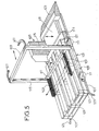
- the box handling device comprises a cart assembly 101 provided with movable forks 103, an elevating device 105, and lateral guide rails 107.
- the cart assembly 101 is formed of two parallel longitudinal members 109 provided with rollers 111 at their ends and connected to each other by a rigid frame 113 with vertical uprights 115.
- the frame 113 comprises a horizontal cross member 117 carrying said forks 103 supporting the bodies. As mentioned previously, this cross member 117 is movable vertically and the forks 103 horizontally on this cross member.
- Device tray 119 elevator is placed at the rear of the handling pallets 121 and between two running boards 123.
- the rails 107 the spacing of which corresponds substantially to the width of the pallets 121 hold the latter in place, as do the running boards 123 at the rear and allow the internal guidance of the carriage assembly 101 which rolls on the ground.
- the front ends 125 of these rails are curved outwards.
- the operation of this device is very simple.
- the handling pallets 121 are first introduced between the rails 107, against the first step 123.
- the carriage assembly 101 is moved back with its forks 103 vertically to the plate 119 of the lifting device.
- An empty box is placed on the forks, then its packaging at constant level is then operated by concomitant elevation of the plate 119 of the lifting device.
- the operator pushes the trolley assembly 101 by its handles 127 while climbing on the steps 123.
- the box arrives vertically from an empty pallet 121, its removal can be engaged .
- the present invention thus provides a simple and reliable handling device for moving bottom cases and which allows them to be packaged at a constant level and transferred to conventional pallets for subsequent handling.
Landscapes
- Engineering & Computer Science (AREA)
- Mechanical Engineering (AREA)
- Chemical & Material Sciences (AREA)
- Combustion & Propulsion (AREA)
- Transportation (AREA)
- Warehouses Or Storage Devices (AREA)
- Pallets (AREA)
- Stacking Of Articles And Auxiliary Devices (AREA)
Applications Claiming Priority (4)
| Application Number | Priority Date | Filing Date | Title |
|---|---|---|---|
| FR8611026 | 1986-07-30 | ||
| FR8611026A FR2602219B1 (fr) | 1986-07-30 | 1986-07-30 | Dispositif de manutention de caisses, notamment de caisses a fond mobile permettant un conditionnement des marchandises a niveau constant |
| FR8701689 | 1987-02-11 | ||
| FR8701689A FR2610610A2 (fr) | 1986-07-30 | 1987-02-11 | Dispositif de manutention de caisses, notamment de caisses a fond mobile permettant un conditionnement des marchandises a niveau constant |
Publications (3)
| Publication Number | Publication Date |
|---|---|
| EP0255448A2 true EP0255448A2 (de) | 1988-02-03 |
| EP0255448A3 EP0255448A3 (en) | 1988-10-19 |
| EP0255448B1 EP0255448B1 (de) | 1990-06-13 |
Family
ID=26225413
Family Applications (1)
| Application Number | Title | Priority Date | Filing Date |
|---|---|---|---|
| EP19870401788 Expired - Lifetime EP0255448B1 (de) | 1986-07-30 | 1987-07-30 | Vorrichtung zum Fördern von Kästen, insbesondere Kästen mit beweglichem Boden zum Umladen von Gegenständen auf gleichbleibendem Niveau |
Country Status (5)
| Country | Link |
|---|---|
| EP (1) | EP0255448B1 (de) |
| DE (1) | DE3763175D1 (de) |
| ES (1) | ES2015077B3 (de) |
| FR (1) | FR2610610A2 (de) |
| PT (1) | PT85466B (de) |
Cited By (1)
| Publication number | Priority date | Publication date | Assignee | Title |
|---|---|---|---|---|
| EP1285867A3 (de) * | 2001-08-21 | 2004-12-15 | Frank Hessemer | Transport- und Lagerbehälter mit lösbarem Hubmodul zum Heben des Behälterbodens |
Family Cites Families (5)
| Publication number | Priority date | Publication date | Assignee | Title |
|---|---|---|---|---|
| US3123023A (en) * | 1964-03-03 | Bronson | ||
| GB724135A (en) * | 1953-06-24 | 1955-02-16 | James Hustler & Son Ltd | Improvements in or relating to lifting trolleys for crates or the like |
| FR2297787A1 (fr) * | 1975-01-16 | 1976-08-13 | Usifroid | Installation de chargement et de dechargement d'une enceinte de traitement |
| US4447041A (en) * | 1981-07-13 | 1984-05-08 | Osaka Taiyo Co., Ltd. | Device for lifting a table |
| FR2558442B3 (fr) * | 1984-01-19 | 1986-05-16 | Socar | Systeme de mise a niveau automatique du fond d'une caisse d'emballage en cours de chargement ou de dechargement |
-
1987
- 1987-02-11 FR FR8701689A patent/FR2610610A2/fr active Pending
- 1987-07-30 EP EP19870401788 patent/EP0255448B1/de not_active Expired - Lifetime
- 1987-07-30 ES ES87401788T patent/ES2015077B3/es not_active Expired - Lifetime
- 1987-07-30 PT PT8546687A patent/PT85466B/pt not_active IP Right Cessation
- 1987-07-30 DE DE8787401788T patent/DE3763175D1/de not_active Expired - Fee Related
Cited By (1)
| Publication number | Priority date | Publication date | Assignee | Title |
|---|---|---|---|---|
| EP1285867A3 (de) * | 2001-08-21 | 2004-12-15 | Frank Hessemer | Transport- und Lagerbehälter mit lösbarem Hubmodul zum Heben des Behälterbodens |
Also Published As
| Publication number | Publication date |
|---|---|
| ES2015077B3 (es) | 1990-08-01 |
| PT85466B (pt) | 1993-07-30 |
| DE3763175D1 (de) | 1990-07-19 |
| EP0255448A3 (en) | 1988-10-19 |
| FR2610610A2 (fr) | 1988-08-12 |
| EP0255448B1 (de) | 1990-06-13 |
| PT85466A (pt) | 1988-07-29 |
Similar Documents
| Publication | Publication Date | Title |
|---|---|---|
| EP0395459A1 (de) | Autonome Frachtlade- und Frachtausladevorrichtung, die in einem Flugzeug integriert ist | |
| EP0199652A1 (de) | Container-Verladevorrichtung | |
| FR2687654A1 (fr) | Structure pour permettre de charger ou decharger des marchandises a transporter avec un dispositif de manutention a bras de levage hydraulique. | |
| CA2461695C (fr) | Dispositif de transfert pour convoyeur lineaire | |
| FR2993872A1 (fr) | Appareil pour empiler et deposer des palettes | |
| EP0131082B1 (de) | Vorrichtung zum Stellen von Paletten auf einen Ladeplatz | |
| EP0255448B1 (de) | Vorrichtung zum Fördern von Kästen, insbesondere Kästen mit beweglichem Boden zum Umladen von Gegenständen auf gleichbleibendem Niveau | |
| FR2673612A1 (fr) | Dispositif pour le depilage et la distribution automatique de barquettes. | |
| EP1012090B1 (de) | Präsentations- und orientierungsvorrichtung für einen behälter zur lagerung und entnahme von artikeln | |
| FR2602219A1 (fr) | Dispositif de manutention de caisses, notamment de caisses a fond mobile permettant un conditionnement des marchandises a niveau constant | |
| FR3023832A1 (fr) | Rehausse pour palette | |
| EP0277880B1 (de) | Beförderungsvorrichtung, insbesondere für Selbstbedienungsläden | |
| FR2930237A1 (fr) | Conteneur pliable a deux surfaces de support superposees c comprenant un plateau mobile a support rabattable. | |
| EP4299403B1 (de) | Wagenvorrichtung zum schienengebundenen transport von gütern auf paletten | |
| FR3097539A1 (fr) | Dispositif de déchargement pour caisses de raisins. | |
| EP3359472A1 (de) | Vorrichtung und verfahren zur herstellung eines lastaufnahmebehälters und anordnung mit diesem behälter sowie derartige vorrichtung | |
| FR2548647A1 (fr) | Dispositif de manutention automatique de charges ou d'articles divers | |
| FR2530201A1 (fr) | Appareil de chargement automatique du volume total d'un vehicule de transport | |
| FR3041949B1 (fr) | Procede et dispositif de preparation de receptacle e charge par chargement en charges dudit receptacle | |
| FR2757831A1 (fr) | Palette de manutention d'objets longitudinaux | |
| WO2017046521A1 (fr) | Dispositif de manutention d'enveloppes de pneumatiques | |
| FR2915462A1 (fr) | Vehicule de chargement / dechargement d'objets vers / depuis un avion. | |
| CH684693A5 (fr) | Rampe pour le chargement et le déchargement du plateau d'un véhicule de transport de marchandises. | |
| FR2662979A1 (fr) | Camion pour le transport de palettes. | |
| EP1163648A2 (de) | Zeitungsverkaufsautomat |
Legal Events
| Date | Code | Title | Description |
|---|---|---|---|
| PUAI | Public reference made under article 153(3) epc to a published international application that has entered the european phase |
Free format text: ORIGINAL CODE: 0009012 |
|
| AK | Designated contracting states |
Kind code of ref document: A2 Designated state(s): BE CH DE ES FR GB IT LI LU NL |
|
| PUAL | Search report despatched |
Free format text: ORIGINAL CODE: 0009013 |
|
| AK | Designated contracting states |
Kind code of ref document: A3 Designated state(s): BE CH DE ES FR GB IT LI LU NL |
|
| 17P | Request for examination filed |
Effective date: 19881006 |
|
| 17Q | First examination report despatched |
Effective date: 19891106 |
|
| GRAA | (expected) grant |
Free format text: ORIGINAL CODE: 0009210 |
|
| AK | Designated contracting states |
Kind code of ref document: B1 Designated state(s): BE CH DE ES FR GB IT LI LU NL |
|
| ITF | It: translation for a ep patent filed | ||
| PGFP | Annual fee paid to national office [announced via postgrant information from national office to epo] |
Ref country code: LU Payment date: 19900711 Year of fee payment: 4 |
|
| REF | Corresponds to: |
Ref document number: 3763175 Country of ref document: DE Date of ref document: 19900719 |
|
| PG25 | Lapsed in a contracting state [announced via postgrant information from national office to epo] |
Ref country code: LU Free format text: LAPSE BECAUSE OF NON-PAYMENT OF DUE FEES Effective date: 19900731 |
|
| PGFP | Annual fee paid to national office [announced via postgrant information from national office to epo] |
Ref country code: NL Payment date: 19900731 Year of fee payment: 4 Ref country code: DE Payment date: 19900731 Year of fee payment: 4 |
|
| GBT | Gb: translation of ep patent filed (gb section 77(6)(a)/1977) | ||
| PGFP | Annual fee paid to national office [announced via postgrant information from national office to epo] |
Ref country code: CH Payment date: 19901008 Year of fee payment: 4 |
|
| PLBE | No opposition filed within time limit |
Free format text: ORIGINAL CODE: 0009261 |
|
| STAA | Information on the status of an ep patent application or granted ep patent |
Free format text: STATUS: NO OPPOSITION FILED WITHIN TIME LIMIT |
|
| 26N | No opposition filed | ||
| PG25 | Lapsed in a contracting state [announced via postgrant information from national office to epo] |
Ref country code: GB Effective date: 19910730 |
|
| PG25 | Lapsed in a contracting state [announced via postgrant information from national office to epo] |
Ref country code: LI Effective date: 19910731 Ref country code: CH Effective date: 19910731 |
|
| PG25 | Lapsed in a contracting state [announced via postgrant information from national office to epo] |
Ref country code: NL Effective date: 19920201 |
|
| NLV4 | Nl: lapsed or anulled due to non-payment of the annual fee | ||
| GBPC | Gb: european patent ceased through non-payment of renewal fee | ||
| REG | Reference to a national code |
Ref country code: CH Ref legal event code: PL |
|
| PG25 | Lapsed in a contracting state [announced via postgrant information from national office to epo] |
Ref country code: DE Effective date: 19920401 |
|
| PGFP | Annual fee paid to national office [announced via postgrant information from national office to epo] |
Ref country code: FR Payment date: 19920703 Year of fee payment: 6 Ref country code: BE Payment date: 19920703 Year of fee payment: 6 |
|
| PGFP | Annual fee paid to national office [announced via postgrant information from national office to epo] |
Ref country code: ES Payment date: 19920713 Year of fee payment: 6 |
|
| ITTA | It: last paid annual fee | ||
| PG25 | Lapsed in a contracting state [announced via postgrant information from national office to epo] |
Ref country code: ES Free format text: LAPSE BECAUSE OF NON-PAYMENT OF DUE FEES Effective date: 19930731 Ref country code: BE Effective date: 19930731 |
|
| BERE | Be: lapsed |
Owner name: SOC. CONTINENTALE DU CARTON ONDULE SOCAR Effective date: 19930731 |
|
| PG25 | Lapsed in a contracting state [announced via postgrant information from national office to epo] |
Ref country code: FR Effective date: 19940331 |
|
| REG | Reference to a national code |
Ref country code: FR Ref legal event code: ST |
|
| REG | Reference to a national code |
Ref country code: ES Ref legal event code: FD2A Effective date: 19940811 |
|
| PG25 | Lapsed in a contracting state [announced via postgrant information from national office to epo] |
Ref country code: IT Free format text: LAPSE BECAUSE OF NON-PAYMENT OF DUE FEES;WARNING: LAPSES OF ITALIAN PATENTS WITH EFFECTIVE DATE BEFORE 2007 MAY HAVE OCCURRED AT ANY TIME BEFORE 2007. THE CORRECT EFFECTIVE DATE MAY BE DIFFERENT FROM THE ONE RECORDED. Effective date: 20050730 |