EP0255514B1 - Automatische zufuhrvorrichtung für werkzeugmaschinen - Google Patents
Automatische zufuhrvorrichtung für werkzeugmaschinen Download PDFInfo
- Publication number
- EP0255514B1 EP0255514B1 EP86901377A EP86901377A EP0255514B1 EP 0255514 B1 EP0255514 B1 EP 0255514B1 EP 86901377 A EP86901377 A EP 86901377A EP 86901377 A EP86901377 A EP 86901377A EP 0255514 B1 EP0255514 B1 EP 0255514B1
- Authority
- EP
- European Patent Office
- Prior art keywords
- gear
- slide
- cutter
- rocker arm
- shaved
- Prior art date
- Legal status (The legal status is an assumption and is not a legal conclusion. Google has not performed a legal analysis and makes no representation as to the accuracy of the status listed.)
- Expired - Lifetime
Links
Images


Classifications
-
- B—PERFORMING OPERATIONS; TRANSPORTING
- B23—MACHINE TOOLS; METAL-WORKING NOT OTHERWISE PROVIDED FOR
- B23F—MAKING GEARS OR TOOTHED RACKS
- B23F23/00—Accessories or equipment combined with or arranged in, or specially designed to form part of, gear-cutting machines
- B23F23/02—Loading, unloading or chucking arrangements for workpieces
- B23F23/04—Loading or unloading arrangements
-
- B—PERFORMING OPERATIONS; TRANSPORTING
- B23—MACHINE TOOLS; METAL-WORKING NOT OTHERWISE PROVIDED FOR
- B23Q—DETAILS, COMPONENTS, OR ACCESSORIES FOR MACHINE TOOLS, e.g. ARRANGEMENTS FOR COPYING OR CONTROLLING; MACHINE TOOLS IN GENERAL CHARACTERISED BY THE CONSTRUCTION OF PARTICULAR DETAILS OR COMPONENTS; COMBINATIONS OR ASSOCIATIONS OF METAL-WORKING MACHINES, NOT DIRECTED TO A PARTICULAR RESULT
- B23Q7/00—Arrangements for handling work specially combined with or arranged in, or specially adapted for use in connection with, machine tools, e.g. for conveying, loading, positioning, discharging, sorting
- B23Q7/04—Arrangements for handling work specially combined with or arranged in, or specially adapted for use in connection with, machine tools, e.g. for conveying, loading, positioning, discharging, sorting by means of grippers
- B23Q7/043—Construction of the grippers
-
- B—PERFORMING OPERATIONS; TRANSPORTING
- B23—MACHINE TOOLS; METAL-WORKING NOT OTHERWISE PROVIDED FOR
- B23Q—DETAILS, COMPONENTS, OR ACCESSORIES FOR MACHINE TOOLS, e.g. ARRANGEMENTS FOR COPYING OR CONTROLLING; MACHINE TOOLS IN GENERAL CHARACTERISED BY THE CONSTRUCTION OF PARTICULAR DETAILS OR COMPONENTS; COMBINATIONS OR ASSOCIATIONS OF METAL-WORKING MACHINES, NOT DIRECTED TO A PARTICULAR RESULT
- B23Q7/00—Arrangements for handling work specially combined with or arranged in, or specially adapted for use in connection with, machine tools, e.g. for conveying, loading, positioning, discharging, sorting
- B23Q7/04—Arrangements for handling work specially combined with or arranged in, or specially adapted for use in connection with, machine tools, e.g. for conveying, loading, positioning, discharging, sorting by means of grippers
- B23Q7/048—Multiple gripper units
-
- Y—GENERAL TAGGING OF NEW TECHNOLOGICAL DEVELOPMENTS; GENERAL TAGGING OF CROSS-SECTIONAL TECHNOLOGIES SPANNING OVER SEVERAL SECTIONS OF THE IPC; TECHNICAL SUBJECTS COVERED BY FORMER USPC CROSS-REFERENCE ART COLLECTIONS [XRACs] AND DIGESTS
- Y10—TECHNICAL SUBJECTS COVERED BY FORMER USPC
- Y10T—TECHNICAL SUBJECTS COVERED BY FORMER US CLASSIFICATION
- Y10T409/00—Gear cutting, milling, or planing
- Y10T409/10—Gear cutting
- Y10T409/100795—Gear cutting with work or product advancing
- Y10T409/100954—Utilizing transfer arm
-
- Y—GENERAL TAGGING OF NEW TECHNOLOGICAL DEVELOPMENTS; GENERAL TAGGING OF CROSS-SECTIONAL TECHNOLOGIES SPANNING OVER SEVERAL SECTIONS OF THE IPC; TECHNICAL SUBJECTS COVERED BY FORMER USPC CROSS-REFERENCE ART COLLECTIONS [XRACs] AND DIGESTS
- Y10—TECHNICAL SUBJECTS COVERED BY FORMER USPC
- Y10T—TECHNICAL SUBJECTS COVERED BY FORMER US CLASSIFICATION
- Y10T409/00—Gear cutting, milling, or planing
- Y10T409/10—Gear cutting
- Y10T409/107632—Gear shaving
Definitions
- the present invention relates to an automatic loader for gear-shaving machines having a rotary cutter in the form of a toothed wheel rotated about a first horizontal axis and means for supporting a gear to be shaved for rotation about a second horizontal axis which is situated below the first axis and is inclined to the first axis, the gear to be shaved meshing in the working position with the shaving cutter and being pressed against said cutter, said loader comprising a movable feeder memberfor conveying the gearto be shaved to the working position, said gear being supported by one end of a rocker arm which is articulated to the feed member and is angularly displaceable relative to the movable feed member against the action of adjustable resilient means when, as a result of the approach of the movable member to the cutter, the gear fails to mesh with the cutter.
- GB-A-949,870 teaches a loading device for gear-shaving machine in which a gear is freely supported in a housing provided in a slide which is movable along a horizontal direction to move the gear radially with respect to the cutter.
- the gear fails to mesh with the cutter the gear is forced to ride on an inclined surface of said housing, which causes rotation of the gear until meshing occurs.
- the teeth of the gear slip on one side on the teeth of the cutter and on the oposite side on a pad which is urged towards the shaving cutter by the action of a helical compression spring.
- the object of the invention is to provide a loader which is more efficient than the known loaders of the prior art and enable the step of meshing the gear to be shaved with the shaving cutter to be effected safely and without risk of damage to the teeth of the gear and the shaving cutter.
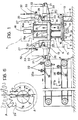
- a gear-shaving machine is indicated 1 and has a shaving cutter 2 in the form of a toothed wheel rotated about a horizontal axis 3.
- the machine 1 further includes means, generally indicated 4, for supporting a gear to be shaved, indicated 22, for rotation about a horizontal axis 5 inclined to and belowthe axis 3, the gear 22 meshing with the teeth of the shaving cutter 2 nd being pressed against the cutter as a result of an upwardly-exerted force.
- a loading unit is adjacent the shaving machine 1 and includes a base 7 having horizontal guides 8 on which a slide 9 is slidable in a direction perpendicular to the axis 5.
- the movement of the slide 9 in both directions is driven by a motor 10 which operates a screw 11 engaged with a nut, not shown, carried by the slide 9.
- a circular platform 12 is rotatably mounted on the slide 9 about a vertical axis.
- the platform 12 is rotated by a motor 13 which drives a sprocket 14 meshing with external teeth 15 of the platform 12.
- Vertical guide columns, indicated 16, are carried by the rotatable platform 12 and are connected at their upper ends by a circular plate 16a.
- a support beam 17 is slidable vertically on the columns 16 and its vertical movement in both directions is driven by a motor 18 through a screw 18a which engages a nut 18b carried by the beam 17.
- Each of the two ends of the support beam 17 is articulated about a horizontal pin 19 to a rocker arm 20 provided at its outer end with a cradle- shaped seat 21 for supporting a gear 22.
- each rocker arm 20 is articulated about a horizontal pin 23, as illustrated in particular in Figure 3, to the lower end of the rod 24 of a piston 25 sealed for sliding in a cylinder 27 by means of a washer 26.
- the cylinder 27 is closed at its upper end by an end wpll28 and at its lower end is articulated about a pin 29 to a forked support 30 carried by the beam 17.
- the chamber 31 of the cylinder 27 between the piston 26 andthewall 28 is filled with a pressurised gas, for example air, supplied through a feed duct 32 and a pressure regulator33 having a knob 34for adjustment of the pressure.
- a pressurised gas for example air
- a manometer for indicating the pressure in the chamber 31 is indicated 35.
- the pressure in the chamber 31 is regulated by means of the regulator 33 in dependence on the weight of the gear 22 supported in the seat 21 of the rocker arm 20.
- An adjustable vent valve 43 is fitted to the wall 28 of the cylinder 27. This valve could also be incorporated in the pressure regulator 33.
- a microswitch 36 is carried by the forked support 30 so as to be operable as a result of a predetermined degree of oscillation of the arm 20 about the pin 19 in the clockwise sense with reference to Figure 3.
- a loading conveyor and an unloading conveyor, indicated 37a and 37b respectively, are located, above one another at the side of the loading unit 1 described above.
- Each of the two conveyors 37a, 37b includes a plurality of plates 38 articulated together and each supporting, by means of a central support 38a, a transverse pin 39 which carries the gears 22.
- These supports comprise plates 40 articulated together and carrying supports 41 with V-shaped notches 42 for receiving the shaft 22a of the gear 22.
- rocker arms 20 are also provided with pairs of supports similar to those illustrated in Figure 5 instead of the cradle- shaped supports 21.
- the other arm 20 opposite the loader 37a contains a gear 22 which has already been shaved.
- the gear 22 to be shaved is placed beneath the shaving cutter 2 in the position illustrated in Figure 6, in which the axis Y of the gear 22 is spaced from the working position X (corresponding to the axis indicated 5 in Figure 2) by a distance A.
- the distance A between the points Y and X corresponds essentially to the distance between the heads of two consecutive teeth of the gear 22.
- the motor 10 which controls the movement of the slide 9 in the direction of the arrow F is actuated, as are the other motors which control the various movements of the loading unit, by a control unit which is preferably a numerical control unit so as to make the slide 9 and hence the gear 22 effect a sequence of displacements each corresponding to a fraction of the distance A.
- each displacement corresponds to a third of the distance A whereby the axis of the gear 22 moves in sequence into the intermediate positions indicated Y1 and Y2 before it reaches the final position, indicated X.
- the slide 9 effects a further axial movement to bring the axis of the gear into the position indicated X and the shaving is started as a result of the rotation of the shaving cutter 2.
- the numerical control unit of the machine causes the descent of the beam 17 by a predetermined distance and the subsequent movement of the slide 9, to bring the axis of the gear from the position Y to the position indicated Y1, and the cycle is repeated until meshing occurs, after which shaving starts.
- the gear which has just been shaved is placed onto the unloading conveyor 37b by the loading unit as a result of the combined movements of the loading unit.
Landscapes
- Engineering & Computer Science (AREA)
- Mechanical Engineering (AREA)
- Gear Processing (AREA)
- Finish Polishing, Edge Sharpening, And Grinding By Specific Grinding Devices (AREA)
Claims (4)
Applications Claiming Priority (2)
| Application Number | Priority Date | Filing Date | Title |
|---|---|---|---|
| IT6721485 | 1985-02-28 | ||
| IT67214/85A IT1183764B (it) | 1985-02-28 | 1985-02-28 | Caricatore automatico per macchine utensili particolarmente per macchine sbarbatrici per ingranaggi |
Publications (2)
| Publication Number | Publication Date |
|---|---|
| EP0255514A1 EP0255514A1 (de) | 1988-02-10 |
| EP0255514B1 true EP0255514B1 (de) | 1990-04-18 |
Family
ID=11300548
Family Applications (1)
| Application Number | Title | Priority Date | Filing Date |
|---|---|---|---|
| EP86901377A Expired - Lifetime EP0255514B1 (de) | 1985-02-28 | 1986-02-13 | Automatische zufuhrvorrichtung für werkzeugmaschinen |
Country Status (6)
| Country | Link |
|---|---|
| US (1) | US4743147A (de) |
| EP (1) | EP0255514B1 (de) |
| JP (1) | JPS62502183A (de) |
| DE (1) | DE3670460D1 (de) |
| IT (1) | IT1183764B (de) |
| WO (1) | WO1986005132A1 (de) |
Families Citing this family (3)
| Publication number | Priority date | Publication date | Assignee | Title |
|---|---|---|---|---|
| DE4323935C1 (de) * | 1993-07-16 | 1994-10-06 | Hurth Maschinen Werkzeuge | Maschine zum Feinbearbeiten der Zahnflanken von zahnradförmigen Werkstücken mit einem innenverzahnten Werkzeug |
| JP2002079420A (ja) * | 2000-09-05 | 2002-03-19 | Kanzaki Kokyukoki Mfg Co Ltd | 歯車複合加工装置 |
| USD864263S1 (en) * | 2018-04-26 | 2019-10-22 | Jinan Jinqiang Laser CNC Equipment Co., Ltd | Loader machine |
Family Cites Families (6)
| Publication number | Priority date | Publication date | Assignee | Title |
|---|---|---|---|---|
| US2733641A (en) * | 1956-02-07 | praeg | ||
| US2692535A (en) * | 1948-04-12 | 1954-10-26 | Nat Broach & Mach | Automatic loading fixture |
| US2782687A (en) * | 1952-05-16 | 1957-02-26 | Mach Tool Works Oerlikon | Gun carriage with pedal-controlled training |
| DE1074367B (de) * | 1957-06-19 | 1960-01-28 | Fa Hermann Pfauter Ludwigs bürg (Wurtt) | Einrichtung zum selbsttätigen Werkstuckwechsel an Walz frasmaschmen |
| GB913191A (en) * | 1960-06-25 | 1962-12-19 | Brown David Ind Ltd | Automatic loading and unloading device for machine tools |
| GB949870A (en) * | 1961-09-28 | 1964-02-19 | Brown David Ind Ltd | New or improved loading device for gear shaving machines |
-
1985
- 1985-02-28 IT IT67214/85A patent/IT1183764B/it active
-
1986
- 1986-02-13 US US06/935,411 patent/US4743147A/en not_active Expired - Lifetime
- 1986-02-13 EP EP86901377A patent/EP0255514B1/de not_active Expired - Lifetime
- 1986-02-13 DE DE8686901377T patent/DE3670460D1/de not_active Expired - Lifetime
- 1986-02-13 JP JP61501162A patent/JPS62502183A/ja active Pending
- 1986-02-13 WO PCT/EP1986/000068 patent/WO1986005132A1/en not_active Ceased
Also Published As
| Publication number | Publication date |
|---|---|
| US4743147A (en) | 1988-05-10 |
| IT1183764B (it) | 1987-10-22 |
| EP0255514A1 (de) | 1988-02-10 |
| WO1986005132A1 (en) | 1986-09-12 |
| JPS62502183A (ja) | 1987-08-27 |
| IT8567214A0 (it) | 1985-02-28 |
| IT8567214A1 (it) | 1986-08-28 |
| DE3670460D1 (de) | 1990-05-23 |
Similar Documents
| Publication | Publication Date | Title |
|---|---|---|
| CN109227292B (zh) | 一种十字工件磨床及控制方法 | |
| EP0255514B1 (de) | Automatische zufuhrvorrichtung für werkzeugmaschinen | |
| CN107009219B (zh) | 镜片加工装置 | |
| CN211034390U (zh) | 一种便于调节玻璃位置的玻璃上片机 | |
| CN106654147A (zh) | 电池自动注液设备 | |
| EP0067469A1 (de) | Finish-Kantenschleifmaschine, insbesondere für Glasplatten | |
| CN207255859U (zh) | 一种自动化磨削坯料的设备 | |
| CN108423223B (zh) | 一种全自动锯片护齿用包管机 | |
| CN215147978U (zh) | 一种抛光机构及具有该抛光机构的抛光系统 | |
| CN211992146U (zh) | 磨削装置及磨床 | |
| JP4052616B2 (ja) | 刃物研削方法および装置 | |
| CN214410898U (zh) | 自动修阻装置 | |
| CN220717405U (zh) | 一种皮带轮旋压成型机 | |
| CA1054830A (en) | Automatic precision working tool | |
| CN212553456U (zh) | 一种汽车轴承加工用夹持装置 | |
| US3606701A (en) | Sectioning machines comprising means controlling the movements of the cutting tool | |
| CN112248705A (zh) | 一种玉石超声波雕刻机 | |
| CN113000731A (zh) | 一种安全可靠的便携式钢筋切断设备 | |
| CN110355552B (zh) | 加工医用产品的自动压表机 | |
| CN213111517U (zh) | 一种吸附旋转上料机构 | |
| CN114030840A (zh) | 一种用于机械加工生产线的自动输送装置 | |
| CN215661375U (zh) | 一种输送带压延用裁边装置 | |
| EP0142655A2 (de) | Vorrichtung zum Schleifen der Schweisszone von Radkränzen von Rädern von Fahrrädern und Kraftfahrzeugen | |
| CN216938796U (zh) | 一种滚齿机自动上下料装置 | |
| CN217427906U (zh) | 马达虚位检测矫正机 |
Legal Events
| Date | Code | Title | Description |
|---|---|---|---|
| PUAI | Public reference made under article 153(3) epc to a published international application that has entered the european phase |
Free format text: ORIGINAL CODE: 0009012 |
|
| 17P | Request for examination filed |
Effective date: 19870720 |
|
| AK | Designated contracting states |
Kind code of ref document: A1 Designated state(s): DE FR GB |
|
| 17Q | First examination report despatched |
Effective date: 19890404 |
|
| RAP3 | Party data changed (applicant data changed or rights of an application transferred) |
Owner name: METALCASTELLO S.R.L. |
|
| RAP3 | Party data changed (applicant data changed or rights of an application transferred) |
Owner name: METALCASTELLO S.R.L. |
|
| GRAA | (expected) grant |
Free format text: ORIGINAL CODE: 0009210 |
|
| AK | Designated contracting states |
Kind code of ref document: B1 Designated state(s): DE FR GB |
|
| REF | Corresponds to: |
Ref document number: 3670460 Country of ref document: DE Date of ref document: 19900523 |
|
| ET | Fr: translation filed | ||
| PLBE | No opposition filed within time limit |
Free format text: ORIGINAL CODE: 0009261 |
|
| STAA | Information on the status of an ep patent application or granted ep patent |
Free format text: STATUS: NO OPPOSITION FILED WITHIN TIME LIMIT |
|
| 26N | No opposition filed | ||
| PGFP | Annual fee paid to national office [announced via postgrant information from national office to epo] |
Ref country code: GB Payment date: 20010118 Year of fee payment: 16 |
|
| PGFP | Annual fee paid to national office [announced via postgrant information from national office to epo] |
Ref country code: DE Payment date: 20010119 Year of fee payment: 16 |
|
| PGFP | Annual fee paid to national office [announced via postgrant information from national office to epo] |
Ref country code: FR Payment date: 20010228 Year of fee payment: 16 |
|
| REG | Reference to a national code |
Ref country code: GB Ref legal event code: IF02 |
|
| PG25 | Lapsed in a contracting state [announced via postgrant information from national office to epo] |
Ref country code: GB Free format text: LAPSE BECAUSE OF NON-PAYMENT OF DUE FEES Effective date: 20020213 |
|
| PG25 | Lapsed in a contracting state [announced via postgrant information from national office to epo] |
Ref country code: DE Free format text: LAPSE BECAUSE OF NON-PAYMENT OF DUE FEES Effective date: 20020903 |
|
| GBPC | Gb: european patent ceased through non-payment of renewal fee |
Effective date: 20020213 |
|
| PG25 | Lapsed in a contracting state [announced via postgrant information from national office to epo] |
Ref country code: FR Free format text: LAPSE BECAUSE OF NON-PAYMENT OF DUE FEES Effective date: 20021031 |
|
| REG | Reference to a national code |
Ref country code: FR Ref legal event code: ST |