EP0255568A2 - Bloc de batteries connectable à un appareil électrique - Google Patents
Bloc de batteries connectable à un appareil électrique Download PDFInfo
- Publication number
- EP0255568A2 EP0255568A2 EP87103519A EP87103519A EP0255568A2 EP 0255568 A2 EP0255568 A2 EP 0255568A2 EP 87103519 A EP87103519 A EP 87103519A EP 87103519 A EP87103519 A EP 87103519A EP 0255568 A2 EP0255568 A2 EP 0255568A2
- Authority
- EP
- European Patent Office
- Prior art keywords
- battery
- battery block
- voltage
- blocks
- block according
- Prior art date
- Legal status (The legal status is an assumption and is not a legal conclusion. Google has not performed a legal analysis and makes no representation as to the accuracy of the status listed.)
- Withdrawn
Links
Images


Classifications
-
- H—ELECTRICITY
- H01—ELECTRIC ELEMENTS
- H01M—PROCESSES OR MEANS, e.g. BATTERIES, FOR THE DIRECT CONVERSION OF CHEMICAL ENERGY INTO ELECTRICAL ENERGY
- H01M50/00—Constructional details or processes of manufacture of the non-active parts of electrochemical cells other than fuel cells, e.g. hybrid cells
- H01M50/20—Mountings; Secondary casings or frames; Racks, modules or packs; Suspension devices; Shock absorbers; Transport or carrying devices; Holders
- H01M50/204—Racks, modules or packs for multiple batteries or multiple cells
- H01M50/207—Racks, modules or packs for multiple batteries or multiple cells characterised by their shape
- H01M50/213—Racks, modules or packs for multiple batteries or multiple cells characterised by their shape adapted for cells having curved cross-section, e.g. round or elliptic
-
- Y—GENERAL TAGGING OF NEW TECHNOLOGICAL DEVELOPMENTS; GENERAL TAGGING OF CROSS-SECTIONAL TECHNOLOGIES SPANNING OVER SEVERAL SECTIONS OF THE IPC; TECHNICAL SUBJECTS COVERED BY FORMER USPC CROSS-REFERENCE ART COLLECTIONS [XRACs] AND DIGESTS
- Y02—TECHNOLOGIES OR APPLICATIONS FOR MITIGATION OR ADAPTATION AGAINST CLIMATE CHANGE
- Y02E—REDUCTION OF GREENHOUSE GAS [GHG] EMISSIONS, RELATED TO ENERGY GENERATION, TRANSMISSION OR DISTRIBUTION
- Y02E60/00—Enabling technologies; Technologies with a potential or indirect contribution to GHG emissions mitigation
- Y02E60/10—Energy storage using batteries
Definitions
- the invention relates to a battery pack that can be combined with an electrical device according to the preamble of patent claim 1.
- a battery pack (battery pack) is known for use in a power tool, in this case in a drilling machine.
- the handle of the drilling machine is designed as a cavity for receiving a battery block, which is held in its inserted position by a locking member pivotably mounted on the underside of the wall of the drilling machine handle.
- Battery blocks of this type are designed with regard to the voltage and the capacity in accordance with the respective requirement, the space available in the device in question also having to be taken into account. This results in a large number of different battery blocks. This is not very efficient and is also expensive.
- the invention has for its object to provide a battery pack system that allows an optimal number of devices to be equipped with a minimum number of battery packs.
- This object is achieved according to the invention in that the insertion part of a number of battery blocks designed for the same battery voltage, but different battery capacity, always has the same axial extension regardless of the respective battery capacity, and the battery receiving part of the respective battery block comes to rest against a contour of the device and can be locked thereon .
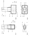
- each of the three battery blocks B1, B2 and 83 consists of an insert part 1 and a battery receiving part 2.
- the insert part contains the connection contacts 3, 4 (-, +) for the drive, not shown, of the device in question , e.g. B. for the drive motor of a power tool.
- the contact designated 5 is a contact for the connection of an NTC or PTC resistor which is used in a known manner to control the charging process when charging the respective battery pack.
- the battery blocks B1 to B3 are each compact units, which do not necessarily have to enable the replacement of individual battery cells, but are generally interchangeable as a unit.
- each battery block has a voltage of 12 volts.
- the capacities of the individual battery blocks B1, E2 and B3 are different. In the present case they are 1.2 Ah, 4 Ah and 7 Ah. Accordingly, the individual 1.2 volt cells are dimensioned so that the battery receptacle parts 2 are each different in volume.
- the insert parts 1, each axially of the same length also have the same cross-sectional shape, which can be rectangular or similar.
- Uie union of the individual battery blocks with the intended, corresponding recess having the housing part of the device in question, for. B. with the at least partially hollow handle 7 of a power tool can be done in any convenient way, for. B. by a snap lock, a clamp lock or the like.
- the respective battery block comes with its upper edges 8 to rest on the relevant part of the device.
- a ring 9 forming the part of a clamp closure is indicated, which engages in a recess 10 in the handle 7 of the power tool.
- the battery pack need not be symmetrical.
- the insertion part 1 and the battery receptacle part 2 can also be laterally offset from one another, as is indicated by dashed lines in FIGS. 5 and 6 with respect to the insertion part.
- Such a battery pack system has a number of advantages.
- One and the same device can be equipped with battery blocks of the same voltage and different capacities, making it possible to use only as much battery capacity and thus only as much weight as is necessary for the work result.
- devices designed for different outputs can be equipped with the appropriate battery block.
- the optimal combination of device or tool, battery pack and charger can be selected.
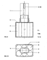
- the battery blocks C1, C2 and C3 according to FIGS. 7 to 12 are each designed for a voltage of 7.2 volts, so that six cells 6 of 1.2 volts each are accommodated in each receiving part 2.
- the capacities of the individual battery blocks are also 1.2 Ah, 4 Ah and 7 Al l . Accordingly, the receiving parts of the individual blocks have different volumes and different weights.
- the insertion parts 1 of the three battery blocks have the same geometrical design or dimensions. In the case of the battery block C1 (see FIGS. 7 and 10) there are four cells 6 in the interior of the insert part 1 and two in the receiving part 2, whereas in the battery blocks C2 and and C3 according to FIGS. 8, 11, 912 all cells are accommodated in the receiving part 2 .
- the locking of the battery blocks C1 to C3 with the relevant housing parts 7 takes place here in the same or in a similar way as indicated in the case of the battery block system B1 to B3.
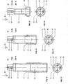
- two 1.2 volt cells 6 each form the respective voltage of 2.4 volts.
- the capacities of the individual battery blocks are again 1.2 Ah, 4 Ah and 7 Ah.
- the insertion part 1 'of the battery block D 1 with 1.2 Ah differs here from those of the battery blocks D 2 and D 3 with 4 and 7 Ah insofar as its cross section is that of section 1 "with the connection contacts 3, 4 and 5, whereas the corresponding cross sections of the two insert parts 1 of the other battery blocks 0 2 and 0 3 are dimensioned somewhat larger, and the battery block U 1 with 1.2 Ah therefore has a correspondingly wide battery receiving part 2 1 (locking cap).
Landscapes
- Chemical & Material Sciences (AREA)
- Chemical Kinetics & Catalysis (AREA)
- Electrochemistry (AREA)
- General Chemical & Material Sciences (AREA)
- Battery Mounting, Suspending (AREA)
Applications Claiming Priority (2)
| Application Number | Priority Date | Filing Date | Title |
|---|---|---|---|
| DE3625135 | 1986-07-25 | ||
| DE19863625135 DE3625135A1 (de) | 1986-07-25 | 1986-07-25 | Mit einem elektrischen geraet vereinigbarer batterieblock |
Publications (2)
| Publication Number | Publication Date |
|---|---|
| EP0255568A2 true EP0255568A2 (fr) | 1988-02-10 |
| EP0255568A3 EP0255568A3 (fr) | 1990-05-02 |
Family
ID=6305942
Family Applications (1)
| Application Number | Title | Priority Date | Filing Date |
|---|---|---|---|
| EP87103519A Withdrawn EP0255568A3 (fr) | 1986-07-25 | 1987-03-11 | Bloc de batteries connectable à un appareil électrique |
Country Status (2)
| Country | Link |
|---|---|
| EP (1) | EP0255568A3 (fr) |
| DE (1) | DE3625135A1 (fr) |
Cited By (10)
| Publication number | Priority date | Publication date | Assignee | Title |
|---|---|---|---|---|
| DE3841735A1 (de) * | 1988-12-10 | 1990-06-13 | Gardena Kress & Kastner Gmbh | Strom-versorgungseinrichtung |
| EP0332475A3 (fr) * | 1988-03-11 | 1991-03-13 | Black & Decker Inc. | Chargeur de batterie et boítiers pour batteries |
| WO1992005919A1 (fr) * | 1990-10-02 | 1992-04-16 | Robert Bosch Gmbh | Dispositif pour outils electriques |
| US5208525A (en) * | 1988-12-10 | 1993-05-04 | Gardena Kress + Kastner Gmbh | Electric power supply assembly for a cordless electric appliance |
| EP0734083A1 (fr) * | 1995-02-23 | 1996-09-25 | Makita Corporation | Dispositif de fixation de piles compactes à des outils électriques |
| US6075341A (en) * | 1999-02-17 | 2000-06-13 | Black & Decker Inc. | Power pack charging system for a power tool |
| GB2369238A (en) * | 2000-11-07 | 2002-05-22 | Paul Rich | Versatile rechargeable battery pack for models |
| US6525511B2 (en) | 2000-08-11 | 2003-02-25 | Milwaukee Electric Tool Corporation | Adapter for a power tool battery |
| WO2003009761A3 (fr) * | 2001-07-26 | 2005-01-13 | Koninkl Philips Electronics Nv | Procede et appareil destines a rendre la taille du bloc-piles d'un dispositif a ultrasons independante de la conception physique du dispositif a ultrasons |
| US7443137B2 (en) | 2000-08-11 | 2008-10-28 | Milwaukee Electric Tool Corporation | Adapter for a power tool battery |
Families Citing this family (5)
| Publication number | Priority date | Publication date | Assignee | Title |
|---|---|---|---|---|
| US5681667A (en) * | 1994-08-11 | 1997-10-28 | Black & Decker Inc. | Battery pack retaining latch for cordless device |
| JP3947949B2 (ja) * | 1998-04-06 | 2007-07-25 | ソニー株式会社 | バッテリーパック、バッテリーチャージャーおよびバッテリーパックを使用する電子機器 |
| US7183745B2 (en) | 2000-08-11 | 2007-02-27 | Milwaukee Electric Tool Corporation | Adapter for a power tool battery |
| JP2006325395A (ja) | 2005-05-17 | 2006-11-30 | Milwaukee Electric Tool Corp | 動力工具、バッテリ、充電器、およびそれらを動作させる方法 |
| JP2006321043A (ja) | 2005-05-17 | 2006-11-30 | Milwaukee Electric Tool Corp | 動力工具、バッテリ、充電器、およびそれらを動作させる方法 |
Family Cites Families (12)
| Publication number | Priority date | Publication date | Assignee | Title |
|---|---|---|---|---|
| US3186878A (en) * | 1962-03-05 | 1965-06-01 | Black & Decker Mfg Co | Quick release latching means for separable case adapted to be telescoped within a housing |
| AT256206B (de) * | 1965-10-13 | 1967-08-10 | Contina Ag | Batteriegehäuse zur wahlweisen Verwendung von Trockenbatterien oder Kleinakkumulatoren |
| DE1538841A1 (de) * | 1966-10-20 | 1970-02-26 | Interelectric Ag | Tragbares elektromotorisch betriebenes Geraet |
| FR2070998A5 (fr) * | 1969-12-15 | 1971-09-17 | Loriot Herve | |
| US3855534A (en) * | 1973-04-23 | 1974-12-17 | J Holcomb | Apparatus for providing power to portable radio transmitters |
| GB1422759A (en) * | 1973-06-08 | 1976-01-28 | Wolf Geraete Gmbh | Battery power pack |
| US3952239A (en) * | 1974-08-23 | 1976-04-20 | The Black And Decker Manufacturing Company | Modular cordless tools |
| US4247603A (en) * | 1979-01-17 | 1981-01-27 | General Electric Company | Plug-in rechargeable battery and socket therefor |
| CH647894A5 (de) * | 1979-04-17 | 1985-02-15 | Autophon Ag | Aufladbare batterie und ladegeraet mit einem koecherfoermigen teil. |
| US4447749A (en) * | 1981-07-29 | 1984-05-08 | Black & Decker Inc. | Cordless electric device having contact increasing means |
| US4468439A (en) * | 1981-10-15 | 1984-08-28 | Canon Kabushiki Kaisha | Battery loading device |
| DE3432294A1 (de) * | 1984-09-03 | 1985-10-10 | Jaroslav 7321 Adelberg Bech | Energie-batteriestab mit stecksystem, kombinierbar (steckbar) zu jeder gleichstromspannung, tragbar auf dem guertel, als tasche oder als koffer, bzw. rucksack |
-
1986
- 1986-07-25 DE DE19863625135 patent/DE3625135A1/de active Granted
-
1987
- 1987-03-11 EP EP87103519A patent/EP0255568A3/fr not_active Withdrawn
Cited By (16)
| Publication number | Priority date | Publication date | Assignee | Title |
|---|---|---|---|---|
| EP0332475A3 (fr) * | 1988-03-11 | 1991-03-13 | Black & Decker Inc. | Chargeur de batterie et boítiers pour batteries |
| EP0561423A3 (fr) * | 1988-03-11 | 1994-01-26 | Black & Decker Inc | |
| DE3841735A1 (de) * | 1988-12-10 | 1990-06-13 | Gardena Kress & Kastner Gmbh | Strom-versorgungseinrichtung |
| US5208525A (en) * | 1988-12-10 | 1993-05-04 | Gardena Kress + Kastner Gmbh | Electric power supply assembly for a cordless electric appliance |
| WO1992005919A1 (fr) * | 1990-10-02 | 1992-04-16 | Robert Bosch Gmbh | Dispositif pour outils electriques |
| US5368954A (en) * | 1990-10-02 | 1994-11-29 | Robert Bosch Gmbh | Device on electric power hand tools |
| EP0734083A1 (fr) * | 1995-02-23 | 1996-09-25 | Makita Corporation | Dispositif de fixation de piles compactes à des outils électriques |
| US5769657A (en) * | 1995-02-23 | 1998-06-23 | Makita Corporation | Attachment structure of battery pack to power-driven tools |
| US6075341A (en) * | 1999-02-17 | 2000-06-13 | Black & Decker Inc. | Power pack charging system for a power tool |
| JP2012135210A (ja) * | 1999-02-17 | 2012-07-12 | Black & Decker Inc | パワーパック充電システムおよび電動工具充電システム |
| US6525511B2 (en) | 2000-08-11 | 2003-02-25 | Milwaukee Electric Tool Corporation | Adapter for a power tool battery |
| US6621246B2 (en) | 2000-08-11 | 2003-09-16 | Milwaukee Electric Tool Corporation | Adapter for a power tool battery |
| US6965214B2 (en) | 2000-08-11 | 2005-11-15 | Milwaukee Electric Tool Corporation | Adapter for a power tool battery and a battery charger |
| US7443137B2 (en) | 2000-08-11 | 2008-10-28 | Milwaukee Electric Tool Corporation | Adapter for a power tool battery |
| GB2369238A (en) * | 2000-11-07 | 2002-05-22 | Paul Rich | Versatile rechargeable battery pack for models |
| WO2003009761A3 (fr) * | 2001-07-26 | 2005-01-13 | Koninkl Philips Electronics Nv | Procede et appareil destines a rendre la taille du bloc-piles d'un dispositif a ultrasons independante de la conception physique du dispositif a ultrasons |
Also Published As
| Publication number | Publication date |
|---|---|
| DE3625135A1 (de) | 1988-02-04 |
| EP0255568A3 (fr) | 1990-05-02 |
| DE3625135C2 (fr) | 1991-01-10 |
Similar Documents
| Publication | Publication Date | Title |
|---|---|---|
| DE3625135C2 (fr) | ||
| DE2361625C2 (de) | Batteriehalter für Stabbatterien | |
| DE3610221C1 (de) | Elektrowerkzeug mit netzunabhaengiger Stromversorgung | |
| DE69211072T2 (de) | Netzunabhängiges Kraftbetriebenes Werkzeug | |
| DE3832246C2 (fr) | ||
| EP0485769A2 (fr) | Chargeur pour batteries rechargeables | |
| DE3839840A1 (de) | Elektrisches handwerksgeraet | |
| DE3110629A1 (de) | "batterie-ladegeraet" | |
| EP0485784A2 (fr) | Chargeur pour batteries rechargeables | |
| DE69011777T2 (de) | Behälter für elektrische, zylindrische Batterien mit verschiedenen Durchmessern. | |
| EP3517253A1 (fr) | Appareil électrique et appareil de charge de batterie | |
| DE202009002787U1 (de) | Akkupack | |
| EP4050716A2 (fr) | Porte-élément et bloc-accumulateur doté d'un porte-élément | |
| DE3150652A1 (de) | "fahrzeug mit elektrischer antriebsmaschine" | |
| EP2203947B1 (fr) | Bloc d'accumulateur et appareil électrique avec des moyens de codage tridimensionnels | |
| DE102020200963A1 (de) | Ladegerät | |
| EP0269096A2 (fr) | Support en forme de cuvette pour téléphone sans cordon | |
| DE3742240A1 (de) | Elektrisches handwerkzeug mit einem akkuteil | |
| DE8619967U1 (de) | Mit einem elektrischen Gerät vereinigbarer Batterieblock | |
| EP0548575A1 (fr) | Dispositif de maintien d'un appareil électrique alimenté par pile avec une connexion à une source d'alimentation | |
| CH658543A5 (de) | Sicherungshalter mit spannungswaehlvorrichtung. | |
| EP0149096B1 (fr) | Cassette pour l'alimentation d'un téléphone sans fil | |
| DE2551663C3 (de) | Batteriekassette | |
| DE2646611C2 (de) | Sicherungsklemme mit auswechselbarer Glimmlampe | |
| DE9107134U1 (de) | Kleinstleuchte, mit einem Schlüssel verbindbare Leuchte |
Legal Events
| Date | Code | Title | Description |
|---|---|---|---|
| PUAI | Public reference made under article 153(3) epc to a published international application that has entered the european phase |
Free format text: ORIGINAL CODE: 0009012 |
|
| 17P | Request for examination filed |
Effective date: 19870326 |
|
| AK | Designated contracting states |
Kind code of ref document: A2 Designated state(s): CH DE GB IT LI NL |
|
| PUAL | Search report despatched |
Free format text: ORIGINAL CODE: 0009013 |
|
| AK | Designated contracting states |
Kind code of ref document: A3 Designated state(s): CH DE GB IT LI NL |
|
| 17Q | First examination report despatched |
Effective date: 19901203 |
|
| STAA | Information on the status of an ep patent application or granted ep patent |
Free format text: STATUS: THE APPLICATION IS DEEMED TO BE WITHDRAWN |
|
| 18D | Application deemed to be withdrawn |
Effective date: 19920527 |
|
| RIN1 | Information on inventor provided before grant (corrected) |
Inventor name: KLUCK, JENS, DIPL.-ING. |