EP0255624A2 - Dispositif pour vider des récipients - Google Patents
Dispositif pour vider des récipients Download PDFInfo
- Publication number
- EP0255624A2 EP0255624A2 EP87110067A EP87110067A EP0255624A2 EP 0255624 A2 EP0255624 A2 EP 0255624A2 EP 87110067 A EP87110067 A EP 87110067A EP 87110067 A EP87110067 A EP 87110067A EP 0255624 A2 EP0255624 A2 EP 0255624A2
- Authority
- EP
- European Patent Office
- Prior art keywords
- force transducer
- container
- fixed support
- pouring
- control
- Prior art date
- Legal status (The legal status is an assumption and is not a legal conclusion. Google has not performed a legal analysis and makes no representation as to the accuracy of the status listed.)
- Granted
Links
Images




Classifications
-
- B—PERFORMING OPERATIONS; TRANSPORTING
- B65—CONVEYING; PACKING; STORING; HANDLING THIN OR FILAMENTARY MATERIAL
- B65F—GATHERING OR REMOVAL OF DOMESTIC OR LIKE REFUSE
- B65F3/00—Vehicles particularly adapted for collecting refuse
- B65F3/02—Vehicles particularly adapted for collecting refuse with means for discharging refuse receptacles thereinto
- B65F3/04—Linkages, pivoted arms, or pivoted carriers for raising and subsequently tipping receptacles
- B65F3/041—Pivoted arms or pivoted carriers
- B65F3/043—Pivoted arms or pivoted carriers with additional means for keeping the receptacle substantially vertical during raising
- B65F3/045—Four-bar linkages
-
- B—PERFORMING OPERATIONS; TRANSPORTING
- B65—CONVEYING; PACKING; STORING; HANDLING THIN OR FILAMENTARY MATERIAL
- B65F—GATHERING OR REMOVAL OF DOMESTIC OR LIKE REFUSE
- B65F3/00—Vehicles particularly adapted for collecting refuse
- B65F3/02—Vehicles particularly adapted for collecting refuse with means for discharging refuse receptacles thereinto
- B65F2003/022—Vehicles particularly adapted for collecting refuse with means for discharging refuse receptacles thereinto the discharging means comprising a device for determining the weight of the content of refuse receptacles
-
- Y—GENERAL TAGGING OF NEW TECHNOLOGICAL DEVELOPMENTS; GENERAL TAGGING OF CROSS-SECTIONAL TECHNOLOGIES SPANNING OVER SEVERAL SECTIONS OF THE IPC; TECHNICAL SUBJECTS COVERED BY FORMER USPC CROSS-REFERENCE ART COLLECTIONS [XRACs] AND DIGESTS
- Y10—TECHNICAL SUBJECTS COVERED BY FORMER USPC
- Y10S—TECHNICAL SUBJECTS COVERED BY FORMER USPC CROSS-REFERENCE ART COLLECTIONS [XRACs] AND DIGESTS
- Y10S414/00—Material or article handling
- Y10S414/13—Handlers utilizing parallel links
Definitions
- the invention relates to a device for emptying containers, in particular a device for emptying garbage containers into the collecting container of a refuse collection vehicle, with a pouring device in which a lifting, tilting or tilting device is attached directly or via intermediate elements to a fixed support provided at the pouring opening or at the pouring edge is and receptacles for the container to be emptied as well as drive devices which are supported directly or via the intermediate members on the fixed support and in which a force transducer of a weighing device equipped with display and / or registration devices for the containers is also included.
- a device of this type known from DE-OS 33 32 058 is equipped with a weighing device included in the lifting and tipping device, with which the containers can be weighed before emptying and after emptying.
- the weighing result is to be used together with the automatic identification of each container at the same time to determine how much container weight has been emptied out of the container, in order to be able to calculate the fees to be paid according to the weight quantity of the refuse in the example of refuse collection.
- a weighing device is installed in the receiving devices on the lifting and tilting device. In this known device, too, the weighing of the container to be emptied and the weighing of the emptied container can only be carried out in the raised, resting position.
- the object of the invention is therefore to improve a device for emptying containers with included weighing equipment to the extent that "dynamic weighing” instead of weighing is made possible in a resting position and thereby stopping and restarting the Movements in the emptying process with the disadvantages and defects caused by them are eliminated.
- the emptying device is also to be improved with regard to operational safety, durability, simple construction and simple operation of the weighing device.
- the force transducer of the weighing device is arranged on such an element of the pouring device, which is connected directly or via an intermediate member to the solid support of the pouring device and that the display and / or registration devices contain a control and computer device Which is designed or adjustable for the selection of measurement values used for the evaluation from the measurement values continuously supplied by the force transducer during the entire uninterrupted course of the emptying process.
- the movements of the pouring device run smoothly during the emptying process.
- the force transducer can remain switched on during the entire motion sequence. There is no longer any need, in a device according to DE-OS 34 47 684, to unlock the force transducer before the weighing process and to lock it again after the weighing process, and thus also the risk that the force transducer could be damaged if the locking is not done after the weighing process . It has been shown that the possibility of the pouring device running in a fluid state only exists if the force transducer is arranged at a point which is largely protected against the occurrence of vibrations.
- this is done by that the force transducer of the weighing device to be disposed on such an element, which directly or via a fixed - connected intermediate member attached to the solid support of the Ein featurevoriques.
- the vibration component picked up by the force transducer is sufficiently low to be able to evaluate it for the evaluation of the measured value or measurement signal given by the force transducer in a control and computing device provided in the display and / or registration device.
- the invention is based on the knowledge that the vibrations occurring in an emptying device according to the invention have fluctuating amplitudes over time, so that there are favorable periods of time for the weighing process in the course of the emptying process.
- the measured values constantly coming from the force transducer are therefore evaluated in the control and computing device only within these time periods which are favorable for the weighing process and are otherwise ignored.
- These periods of time, which are favorable for the weighing process can vary from emptying device to emptying device. However, they can be set in a simple manner by appropriately adapting the control and computing device.
- control and arithmetic device is designed for the selection of measured values within a set or adjustable period of time, starting from the acceptance of a control signal and for this purpose in the control devices; connected to the pouring device, which emits a control signal in the initial stage of the emptying process.
- This signal transmitter can be started by actuating the control devices of the pouring device to initiate an emptying process and can emit a control signal that switches the control and computing device into effect via an optionally adjustable timer as soon as the time period favorable for the weighing process reaches in the initial stage of the emptying process is.
- the length of the measuring period can be set up or adjustable on the signal transmitter or on the control and computing device itself. In this way, a time cycle window is obtained which ensures that the most effective and cheapest time range is used within the emptying process for the weighing process, and within which the evaluation takes place.
- a second cycle window of this type can be set up in that the control and computing device is connected to a signal transmitter which, in addition to the above-described first delivery of a control signal, also has another in the initial stage of the backward movement of the emptied container Emits control signal.
- Another possibility for the generation of two clock windows in the context of the invention is that the control and computing device is connected to two signal transmitters, one of which responds in the initial stage of the emptying process and the second in the initial stage of the backward movement of the emptied container.
- control and computing device contains a low-pass filter for the measured values supplied by the force transducer.
- a low-pass filter can be easily calculated and designed on the basis of the vibration properties of the lifting and tilting device and its parts and on the basis of the desired vibration damping.
- a further possibility for reducing the vibrations and their consequences for the weighing process is that in the force path between the lifting and tipping device and the fixed support in which the Force transducer of the weighing device is arranged, additional damping and buffering elements are provided.
- an additional force transducer for the weighing device can also be attached to another element or at a point in the force path separated from the same element of the lift-and-tilt or tilting device, all force transducers being attached to a device provided in the display and / or registration device for comparing those fed to it simultaneously Measured values trained computers are connected. Since the force transducers attached to different elements or at different points of an element basically provide the same measured values, but are superimposed with vibration components that differ greatly from one another, such a comparative computer can be used to eliminate the vibration components superimposing the actual measured values.
- falsifications of the measurement result resulting from the inclination of the pouring device should also be eliminated, whereas falsifications of the measurement result resulting from the different center of gravity of the container to be emptied have emerged as insignificant.
- a change in the inclination of the pouring device can occur in that, with the loading state of the collection container, the suspension of the vehicle drops more strongly on the rear axle.
- An even greater change in the inclination of the pouring device results when a garbage truck is on a sloping road.
- the force transducer in a preferred embodiment of the invention, in which the drive device contains a cylinder-piston arrangement which is supported on one side directly or via a permanently attached intermediate member on the fixed support and is operated with pressure medium, the force transducer according to the invention is in the area of a bearing eye of this cylinder-piston assembly Preferably, the bearing eye facing the solid support is attached.
- a force transducer for the weighing device can also be attached in the area of both bearing eyes of the cylinder-piston arrangement.
- the force transducer is inserted into a bore which is mounted in the end of the cylinder and / or the piston rod forming the respective bearing eye.
- the force transducer can also be attached to the support element for the cylinder-piston arrangement, which forms a bearing eye and is attached to the fixed support or a fixed intermediate member, for example in a bore provided for this purpose in the support element.
- the display and / or registration devices can contain a time-controlled control and computing device which only releases the measured values coming from the force transducer in those time sections in which the cylinder-piston arrangement exerts practically vertically directed lifting force on the container. This vertically directed lifting force can be used for lifting the container and supporting the lowering movement of the container of the lifting process and during the lowering process.
- the lifting and tipping device contains a swivel shaft mounted directly or via a fixed intermediate member (intermediate frame) on the fixed support
- the vertical component of the swivel shaft on the fixed support can, according to the invention, be mounted on the bearing device of the swivel shaft Transmitted load measuring force transducer provided, preferably inserted into a bore made in this storage device.
- a further embodiment of the invention in which the pouring-in device has an intermediate frame as an intermediate element for limited vertically movable attachment to the structural parts of a collecting container forming the solid support, for example on a garbage truck, this intermediate frame is resting on force transducers on the structural parts of the collecting container.
- the load transmitted from the intermediate frame to the superstructure parts of the collecting container is measured, the weight of the container being the difference between this currently transmitted load and a base load generated by the pouring device. It is certainly a certain defect that the base load measured in any case is greater than the difference between the instantaneous load and the base load, which corresponds to the weight of the container.
- the intermediate frame can be attached to the structural parts of the collecting container that form the solid support via oscillating metal elements. It is also possible, to attach the intermediate frame via articulated levers to the structural parts of the collecting container which form the fixed support, it being further advantageous for this possibility to add effective mechanical damping and buffering elements to the articulated levers between the intermediate frame and the structural parts of the collecting container.
- a garbage truck 10 is equipped with a collecting container 11.
- a pouring opening 12 is formed on the rear wall 13 of the collecting container 11 and is surrounded by an intermediate frame 14.
- This intermediate frame 14 carries the emptying device 15 designed in this example as a lifting and tipping device.
- the emptying device 15 is equipped with a lifting and tipping frame 35, which on its upper part has a support bar which extends across the width of the pouring opening 12 for hanging the waste containers to be emptied and can be raised to an upper stroke position by means of cylinder-piston unit 32.
- the intermediate frame 14 is limitedly vertically movable on the rear wall 13 of the collecting container 11 by means of vibrating metal elements 16 and sits with its lower edge on force transducers (not shown) (as can be seen more clearly in FIG. 2).
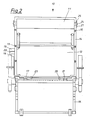
- FIG. 2 shows the rear view of a refuse collection vehicle 10 with a modified pouring device 15.
- the pouring opening 12 of the collecting container 11 is surrounded by an intermediate frame 14.
- the intermediate frame 14 also carries the pouring device 15 in this example and is connected to the collecting container 11 via vibrating metals 16.
- the intermediate frame 14 rests on force transducers 17 which are arranged firmly on the rear wall 13 below the lower edge of the intermediate frame 14.
- the force transducers 17 are connected via electrical lines 18 to a display device 19 which contains a control and computing device 29 in order to transmit the measured values coming from the force transducers 17 to the display device 19 and to a registration device connected to it.
- the display device 19 can contain an electrical low-pass filter, which eliminates the electrical vibrations occurring in the measured values of the force transducers 17 due to mechanical vibrations on the intermediate frame 14 and thereby excludes or at least substantially eliminates errors in the weight display or weight registration reduced.
- the force transducers 17 are set up in such a way that the increased load occurring on the intermediate frame 14 due to the lifting of the container is converted into a measured value for the corresponding container weight and displayed.
- the intermediate frame 14, which is floatingly attached to the collecting container 13, is held on the collecting container 13 by means of guide lugs 20 in such a way that it can essentially only carry out vertical movements.
- the guide plates 20 are in turn mounted on the collecting container 13 in slideways 21 and engage with a converging surface 23 of the intermediate frame 14 via an obliquely starting surface 22.
- the intermediate frame 14 can be raised over the surfaces 22, 23 so that the force transducers 17 are relieved for the general driving operation of the garbage truck 11.
- the intermediate frame 14 is locked on the collecting container 13 with the guide tabs 20, which are designed as a locking device 25 in a partial area.
- a connection via articulated lever 26 is provided instead of the connection of the intermediate frame 14 to the collecting container 3 via oscillating metals.
- upper stops 27 and lower stops 28 are advantageously provided; which limit the greater mobility of the intermediate frame in the vertical direction compared to the attachment by means of oscillating metal.
- the stops 27 and 28 are particularly effective when the locking of the intermediate frame 14 via the guide tabs 20 fails due to a fault or is not actuated in the case of short travel distances between the individual emptying processes.
- the movement of the intermediate frame 14 must be limited overall in order to avoid unnecessary use To prevent wear and tear during rough operation of the garbage disposal.
- the load on the force transducers 17 is basically relieved via the guide straps 20 provided with drives 24.
- the number of force transducers 17 per device is to be selected according to the type and size of the respective device. A single force transducer can be sufficient. Contrary to the example shown, it can also be advantageous to design the attachment of the intermediate frame 14 to the collecting container 13 such that e.g. a lock is released only at the end of the stroke, and thus the intermediate frame 14 is released for floating storage for a short period of time in order to use this short period of time in the manner of a cycle window for determining the container weight. This process could also be separately controlled by the lever arrangement of the pouring device 15.
- a pouring device 15 with a lifting and tilting device 31 is provided.
- This lifting and tilting device 31 contains a cylinder-piston unit 32 which supplies the force for both the lifting process and the tilting process.
- a cylinder-piston unit could also be provided only for the lifting process and a separate pressure medium motor for the tilting process.
- an intermediate frame 14 carrying the pouring device 15 is firmly inserted into the rear wall 13 of the collecting container 11.
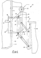
- this intermediate frame 14 carries the swivel axis 33 with swivel arm 34 and lifting and tilting frame 35, which is attached to the swivel arm 34 by means of a four-bar guide.
- the cylinder-piston unit 32 provided for the lifting and tilting movement is included inserted between a bearing eye 36 fixedly attached to the intermediate frame 14 and an actuating arm 37 of the four-bar guide, namely with its cylinder eye 38 to the fixed bearing eye 36 and articulated with a piston eye 39 to the actuating lever 37.
- a bore 40 is made in the cylinder eye 38, into which a force transducer 17 is inserted.
- This force transducer 17 absorbs the axial force developed by the cylinder-piston unit 32 and generates a measured value thereof, which is transmitted via electrical lines 18 to the display and recording device 19, specifically via its control and computing device 29.
- the force transducer 17 is rod-shaped in this example and extends in the bore 40 up to the area of the central axis 41 of the cylinder and the cylinder eye 38.
- a force transducer 17 can also be fitted in the eye 39 of the piston rod.
- the attachment of the force transducer 17 in the cylinder eye 38 will be preferred.
- the force transducer 17 is pressurized in accordance with the force applied by the cylinder-piston unit 32 in the sense of the arrows 42 shown in FIG.
- the construction of the emptying device 15 is essentially the same as in the example in FIGS. 4 and 5.
- a rod-shaped force transducer 17 is inserted into a bore 43 in the fixed bearing eye 36, by means of which the cylinder-piston unit 32 is articulated * on the fixedly mounted intermediate frame 14 *.
- the attachment of the force transducer 17 in the fixed bearing eye 36 is such that the rod-shaped force transducer 17 effectively engages in the force path between the mounting of the cylinder-piston unit 32 and the intermediate frame 14.
- the force transducer 17 is connected to the display device 19 or its control and computing device 29 via electrical lines 18.
- the pouring-in device 15 is in turn provided with a swivel arm 34 which holds the weight of the container to be emptied and which is mounted with its swivel shaft 33 on a carrier plate 44 on the intermediate frame 14.
- a bearing arrangement 45 for the pivot shaft 33 is firmly connected to the carrier plate 44.
- a force transducer 17 is inserted vertically below the pivot shaft 33, which in this example can be designed like a can with an axial direction of action. This force transducer 17 thus responds to the load transmitted from the pivot shaft 33 to the bearing arrangement 45.
- This load is in turn dependent on the weight of the container, which is held directly or indirectly on the swivel arm.
- the force transducer 17 thus outputs a measurement value, which is dependent on the weight of the container attached to the swivel arm 34, via the electrical lines 18 to the display device 19 or its control and computing device 29.
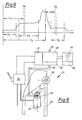
- actuation of the pressure medium control device 48 begins the preferably hydraulic pressure medium application to the cylinder-piston unit 32.
- the lifting and tipping frame 35 moves to the waste container 30 (FIG. 4).
- the measured value that occurs corresponds to the weight of the lifting / tilting frame 35.
- the lifting and tipping frame 35 has gripped the container 30 to be emptied, there is a steep increase in the measured value transmitted from the force transducer 17 to the control and computing device 29 until it corresponds to the total weight of the lifting and tipping frame 35, container and container content.
- the pressure medium control device 48 is changed over after a time t 3 and the cylinder-piston unit 32 is relieved of its pressure medium loading.
- the swivel arm 34 then pivots back with the lifting / tilting frame 35 and the emptied container 30, which can be seen from the falling branch of the curve tn FIG. 9.
- the lifting and tilting frame 35 with the attached empty container 30 is lowered during a period t 4 .
- t 4 there is a measured value coming from the force transducer 17 which corresponds to the weight of the lifting and tilting frame 35 and the emptied container 30. If the container is then placed on the floor, there is a further drop in the measured value. The remaining value then only corresponds to the weight of the lifting / tilting frame 35.
- This course of the measured value curve according to FIG. 9 can be used with the device according to FIG. 8 in cooperation with the switch attached to the pressure medium control device 48 as follows for determining the container weight or the weight of the container contents: at point "0" according to FIG. 9 the timing element contained in the control part 47 is started, which then expires over a period t 5 . At the end of this period t 5 , the arithmetic part 48 is activated. This activation of the arithmetic part is maintained over a period of time t 6 thus forms a clock window. Within this cycle window t 6 , the measurement value present is evaluated and stored in order to determine the weight of the lifting / tilting frame 35, container 30 and container content.
- a further timing element is started in the control part 47, which runs over a period t 7 and a second clock window t 8 .
- the computer part 48 is in turn activated in order to convert the measured value present into the weight of the lifting and tipping frame and the emptied container.
- This second measured value or this second, converted weight value is subtracted from the stored measured value or weight value originating from the clock window t 6 , so that the resulting weight difference corresponds to the weight of the container contents.
- This weight of the container contents is fed to the display device 19 and the registration device 49.
- this evaluation method offers the advantage that it is independent of the tare weight of the container 30 to be emptied. If only containers 30 with the same empty weight are to be emptied, the weight determination in the cycle window t 6 alone the weight of the container contents can be determined by subtracting the known empty weight of the container and the known weight of the lifting and tilting frame from the determined weight value. A somewhat smaller, relative error (percentage error) can then be expected.
- the weight determination in the second cycle window t 8 can also be used for control control both in the first and in the second mode of operation.
Landscapes
- Engineering & Computer Science (AREA)
- Mechanical Engineering (AREA)
- Refuse-Collection Vehicles (AREA)
- Refuse Collection And Transfer (AREA)
- Input Circuits Of Receivers And Coupling Of Receivers And Audio Equipment (AREA)
- Supplying Of Containers To The Packaging Station (AREA)
- Control And Other Processes For Unpacking Of Materials (AREA)
Applications Claiming Priority (2)
| Application Number | Priority Date | Filing Date | Title |
|---|---|---|---|
| DE3624590 | 1986-07-21 | ||
| DE3624590 | 1986-07-21 |
Publications (3)
| Publication Number | Publication Date |
|---|---|
| EP0255624A2 true EP0255624A2 (fr) | 1988-02-10 |
| EP0255624A3 EP0255624A3 (en) | 1989-08-30 |
| EP0255624B1 EP0255624B1 (fr) | 1991-10-02 |
Family
ID=6305624
Family Applications (1)
| Application Number | Title | Priority Date | Filing Date |
|---|---|---|---|
| EP87110067A Expired - Lifetime EP0255624B1 (fr) | 1986-07-21 | 1987-07-11 | Dispositif pour vider des récipients |
Country Status (5)
| Country | Link |
|---|---|
| US (1) | US4824315A (fr) |
| EP (1) | EP0255624B1 (fr) |
| AT (1) | ATE67980T1 (fr) |
| DE (1) | DE3773445D1 (fr) |
| ES (1) | ES2025105B3 (fr) |
Families Citing this family (25)
| Publication number | Priority date | Publication date | Assignee | Title |
|---|---|---|---|---|
| US5004392A (en) * | 1984-02-20 | 1991-04-02 | Zoller-Kipper Gmbh | Device for emptying containers, especially refuse bins |
| DE8707422U1 (de) * | 1987-05-23 | 1987-08-13 | Pontech Gesellschaft für technologische Entwicklungen mbH, 28357 Bremen | Vorrichtung zum gewichtsmäßigen Erfassen von Material, vorzugsweise Müll, an einem Sammelfahrzeug |
| GB8724360D0 (en) * | 1987-10-17 | 1987-11-18 | Allen Motor Bodies Ltd Jack | Collection vehicle & method of tipping bin |
| DE3910660A1 (de) * | 1989-04-03 | 1990-10-04 | Zoeller Kipper | Sicherheitsschaltanordnung fuer hubkipp- oder kippvorrichtungen |
| US4995781A (en) * | 1989-11-03 | 1991-02-26 | Herzog Kenneth J | Movable auxiliary hopper |
| DE4012402A1 (de) * | 1990-04-19 | 1991-10-24 | Otto Lift Systeme Gmbh | Waegeeinrichtung fuer abfallbehaelter an einem muellsammelfahrzeug |
| NL9101192A (nl) * | 1990-10-30 | 1992-05-18 | Nuyts Orb Nv | Vervoermiddel, zoals een vuilniswagen of dergelijke, voorzien van een laad-kipmechanisme voor het hanteren van containers of dergelijke. |
| US5245137A (en) * | 1990-12-21 | 1993-09-14 | Mobile Computing Corporation | Load measuring system for refuse trucks |
| CA2032983C (fr) * | 1990-12-21 | 1999-09-07 | Allan Bowman | Systeme de pesage du chargement des camions a ordures |
| NL9100395A (nl) * | 1991-03-05 | 1992-10-01 | Mettler Toledo Bv | Weeginrichting. |
| AT399048B (de) * | 1991-07-05 | 1995-03-27 | Riha Wolfgang Dr | Müllmengenwäge- und volumenerfassungssystem |
| DE4138289A1 (de) * | 1991-11-21 | 1993-05-27 | Walterscheid Gmbh Jean | Zugstrebe |
| US5879015A (en) * | 1992-02-10 | 1999-03-09 | Ramsey; Michael P. | Method and apparatus for receiving material |
| DE4231211C1 (de) * | 1992-09-18 | 1994-02-10 | Schenck Ag Carl | Vorrichtung zum Entleeren von Großraumbehältern |
| DE4419328C1 (de) * | 1994-06-02 | 1995-07-27 | Zoeller Kipper | Vorrichtung zum Entleeren von Großbehältern |
| US5525022A (en) * | 1994-12-05 | 1996-06-11 | Automated Refuse Equipment, Inc. | Apparatus for engaging and lifting a refuse container |
| US5666295A (en) * | 1996-01-05 | 1997-09-09 | Sentek Products | Apparatus and method for dynamic weighing of loads in hydraulically operated lifts |
| WO1998021555A1 (fr) * | 1996-11-13 | 1998-05-22 | Arthur Kellenbach | Montage d'elements supports de charge calibres |
| US7211747B2 (en) * | 2003-08-26 | 2007-05-01 | Shred-Tech Corporation | Bin lifting and weigh scale arrangement |
| CN100540416C (zh) * | 2005-03-02 | 2009-09-16 | 重庆耐德新明和工业有限公司 | 多功能垃圾压缩收运箱 |
| ES2354779B1 (es) * | 2008-06-20 | 2011-07-27 | Victor Esteve Noguera | Dispositivo elevador pesador de residuos y basuras. |
| US20100278620A1 (en) * | 2009-05-04 | 2010-11-04 | Rimsa James R | Refuse receptacle lifter mounting/weighing assembly |
| CH702073A2 (de) | 2009-10-27 | 2011-04-29 | Villiger Entsorgungssysteme Ag | Einwurfschacht für unterirdische Sammeleinrichtung für Abfälle. |
| FR2998280B1 (fr) * | 2012-11-20 | 2016-12-30 | Pb Environnement | Vehicule de collecte de dechets avec leve-conteneurs ameliore |
| GB2587641B (en) * | 2019-10-02 | 2021-09-22 | Advanced Mfg Control Systems Ltd | Refuse collection vehicle weighing system |
Family Cites Families (11)
| Publication number | Priority date | Publication date | Assignee | Title |
|---|---|---|---|---|
| US2635868A (en) * | 1950-09-29 | 1953-04-21 | George C Reid | Load weighing device for hydraulic loaders |
| US2877906A (en) * | 1954-02-08 | 1959-03-17 | Clark Equipment Co | Load weighing device |
| US2926796A (en) * | 1955-12-05 | 1960-03-01 | Koehring Co | Self-charging mixing and dispensing apparatus |
| GB970280A (en) * | 1962-03-01 | 1964-09-16 | Cole E K Ltd | Improvements relating to the weighing of a load carried by a crane or the like |
| US3371526A (en) * | 1965-05-05 | 1968-03-05 | Radson Engineering Corp | Load cell |
| SE7313231L (sv) * | 1973-09-28 | 1975-04-01 | Svenska Cellulosa Ab | Metanordning |
| EP0066578A1 (fr) * | 1980-12-16 | 1982-12-15 | Ergotest Ab | Dispositif de pesage electronique pour appareil de levage a palette |
| DE3332058A1 (de) * | 1983-09-06 | 1985-03-21 | Bartholomäus 6145 Lindenfels Bitsch | Greif-, hub- und kippeinrichtung zur automatischen entleerung von muellbehaeltern |
| DE3405997C2 (de) * | 1984-02-20 | 1987-01-08 | Zöller-Kipper GmbH, 6500 Mainz | Vorrichtung zum Entleeren von Behältern, insbesondere von Müllbehältern in Sammelbehälter |
| DE3447648C2 (de) * | 1984-12-28 | 1986-12-11 | Garbade, Rolf, 2804 Lilienthal | Verfahren und Vorrichtung zur gewichtsmäßigen Erfassung von Material, vorzugsweise Müll, bei der Entleerung in ein Sammelfahrzeug |
| US4677579A (en) * | 1985-09-25 | 1987-06-30 | Becor Western Inc. | Suspended load measurement system |
-
1987
- 1987-07-11 EP EP87110067A patent/EP0255624B1/fr not_active Expired - Lifetime
- 1987-07-11 ES ES87110067T patent/ES2025105B3/es not_active Expired - Lifetime
- 1987-07-11 DE DE8787110067T patent/DE3773445D1/de not_active Expired - Lifetime
- 1987-07-11 AT AT87110067T patent/ATE67980T1/de not_active IP Right Cessation
- 1987-07-20 US US07/075,733 patent/US4824315A/en not_active Expired - Fee Related
Also Published As
| Publication number | Publication date |
|---|---|
| ES2025105B3 (es) | 1992-03-16 |
| EP0255624A3 (en) | 1989-08-30 |
| US4824315A (en) | 1989-04-25 |
| ATE67980T1 (de) | 1991-10-15 |
| EP0255624B1 (fr) | 1991-10-02 |
| DE3773445D1 (de) | 1991-11-07 |
Similar Documents
| Publication | Publication Date | Title |
|---|---|---|
| EP0255624B1 (fr) | Dispositif pour vider des récipients | |
| DE69310786T2 (de) | Verfahren zum Sammeln und Aufzeichnen von Abfällen und Wägebehälter | |
| EP2489273B1 (fr) | Dispositif et procédé d'alimentation d'une machine traitant des produits alimentaires, notamment d'une machine de remplissage ou d'un dispositif de coupe à l'aide de produits alimentaires | |
| DE3447648C2 (de) | Verfahren und Vorrichtung zur gewichtsmäßigen Erfassung von Material, vorzugsweise Müll, bei der Entleerung in ein Sammelfahrzeug | |
| EP0364835A1 (fr) | Véhicule de ramassage d'ordures | |
| DE3840112C1 (fr) | ||
| DE3722184C2 (de) | Vorrichtung zum entleeren von behaeltern | |
| DE69707803T2 (de) | Verfahren zur Hubsteuerung | |
| DE4010065A1 (de) | Verfahren zum mengenbezogenen entsorgen von haushalts-und gewerbemuell und mengenbezogenes entsorgungssysstem fuer derartigen muell | |
| EP2994726B1 (fr) | Porte-charge élastiquement déformable comprenant un dispositif de mesure de la charge | |
| EP1371603A2 (fr) | Procédé de contrôle d'au moins un mouvement d'un chariot de manutention | |
| EP1247765B1 (fr) | Dispositif de surveillance de charge pour marche-pieds | |
| DE2637873C2 (de) | Transportfahrzeug für an einem Ende offene, kippbare Behälter | |
| DE4237143A1 (en) | Compactor for refuse in refuse skip - has swinging panel with flap which is retracted on up-stroke of panel | |
| EP0571821A1 (fr) | Véhicule à ordures automobile | |
| EP0728681B1 (fr) | Procédé et dispositif de commande d'un dispositif de levage | |
| EP1508268B1 (fr) | Presse à balles rondes | |
| DE69519162T2 (de) | Vorrichtung zum wiegen und entleeren von abfallbehältern | |
| EP0685411B1 (fr) | Dispositif pour vider des grands récipients | |
| DE4003020A1 (de) | Verfahren zum wiegen eines gutes | |
| DE19747869A1 (de) | Schwerlastfahrzeug mit Überlastsicherung | |
| DE69200139T2 (de) | Hydraulisch betätigter, auf Scheren gestützter Hebewagen. | |
| DE19849367C2 (de) | Vorrichtung zum Abladen von Containern | |
| DE2750479A1 (de) | Muellwagen | |
| DE202011110834U1 (de) | Vorrichtung zum Beschicken einer Lebensmittel verarbeitenden Maschine, insbesondere einer Füllmaschine oder einem Kutter mit Lebensmitteln |
Legal Events
| Date | Code | Title | Description |
|---|---|---|---|
| PUAI | Public reference made under article 153(3) epc to a published international application that has entered the european phase |
Free format text: ORIGINAL CODE: 0009012 |
|
| AK | Designated contracting states |
Kind code of ref document: A2 Designated state(s): AT BE CH DE ES FR GB IT LI NL SE |
|
| PUAL | Search report despatched |
Free format text: ORIGINAL CODE: 0009013 |
|
| AK | Designated contracting states |
Kind code of ref document: A3 Designated state(s): AT BE CH DE ES FR GB IT LI NL SE |
|
| 17P | Request for examination filed |
Effective date: 19890925 |
|
| 17Q | First examination report despatched |
Effective date: 19900724 |
|
| GRAA | (expected) grant |
Free format text: ORIGINAL CODE: 0009210 |
|
| AK | Designated contracting states |
Kind code of ref document: B1 Designated state(s): AT BE CH DE ES FR GB IT LI NL SE |
|
| REF | Corresponds to: |
Ref document number: 67980 Country of ref document: AT Date of ref document: 19911015 Kind code of ref document: T |
|
| GBT | Gb: translation of ep patent filed (gb section 77(6)(a)/1977) | ||
| REF | Corresponds to: |
Ref document number: 3773445 Country of ref document: DE Date of ref document: 19911107 |
|
| ET | Fr: translation filed | ||
| ITF | It: translation for a ep patent filed | ||
| REG | Reference to a national code |
Ref country code: ES Ref legal event code: FG2A Ref document number: 2025105 Country of ref document: ES Kind code of ref document: B3 |
|
| PLBE | No opposition filed within time limit |
Free format text: ORIGINAL CODE: 0009261 |
|
| STAA | Information on the status of an ep patent application or granted ep patent |
Free format text: STATUS: NO OPPOSITION FILED WITHIN TIME LIMIT |
|
| 26N | No opposition filed | ||
| EAL | Se: european patent in force in sweden |
Ref document number: 87110067.3 |
|
| PGFP | Annual fee paid to national office [announced via postgrant information from national office to epo] |
Ref country code: SE Payment date: 20000721 Year of fee payment: 14 Ref country code: ES Payment date: 20000721 Year of fee payment: 14 Ref country code: CH Payment date: 20000721 Year of fee payment: 14 Ref country code: AT Payment date: 20000721 Year of fee payment: 14 |
|
| PGFP | Annual fee paid to national office [announced via postgrant information from national office to epo] |
Ref country code: BE Payment date: 20000726 Year of fee payment: 14 |
|
| PG25 | Lapsed in a contracting state [announced via postgrant information from national office to epo] |
Ref country code: AT Free format text: LAPSE BECAUSE OF NON-PAYMENT OF DUE FEES Effective date: 20010711 |
|
| PG25 | Lapsed in a contracting state [announced via postgrant information from national office to epo] |
Ref country code: SE Free format text: LAPSE BECAUSE OF NON-PAYMENT OF DUE FEES Effective date: 20010712 Ref country code: ES Free format text: LAPSE BECAUSE OF NON-PAYMENT OF DUE FEES Effective date: 20010712 |
|
| PG25 | Lapsed in a contracting state [announced via postgrant information from national office to epo] |
Ref country code: LI Free format text: LAPSE BECAUSE OF NON-PAYMENT OF DUE FEES Effective date: 20010731 Ref country code: CH Free format text: LAPSE BECAUSE OF NON-PAYMENT OF DUE FEES Effective date: 20010731 Ref country code: BE Free format text: LAPSE BECAUSE OF NON-PAYMENT OF DUE FEES Effective date: 20010731 |
|
| REG | Reference to a national code |
Ref country code: GB Ref legal event code: IF02 |
|
| BERE | Be: lapsed |
Owner name: ZOLLER-KIPPER G.M.B.H. Effective date: 20010731 |
|
| EUG | Se: european patent has lapsed |
Ref document number: 87110067.3 |
|
| REG | Reference to a national code |
Ref country code: CH Ref legal event code: PL |
|
| PGFP | Annual fee paid to national office [announced via postgrant information from national office to epo] |
Ref country code: GB Payment date: 20020626 Year of fee payment: 16 |
|
| PGFP | Annual fee paid to national office [announced via postgrant information from national office to epo] |
Ref country code: NL Payment date: 20020717 Year of fee payment: 16 Ref country code: FR Payment date: 20020717 Year of fee payment: 16 |
|
| PG25 | Lapsed in a contracting state [announced via postgrant information from national office to epo] |
Ref country code: GB Free format text: LAPSE BECAUSE OF NON-PAYMENT OF DUE FEES Effective date: 20030711 |
|
| NLS | Nl: assignments of ep-patents |
Owner name: ENVICOMP SYSTEMLOGISTIK GMBH & C. KG |
|
| REG | Reference to a national code |
Ref country code: GB Ref legal event code: 732E |
|
| PG25 | Lapsed in a contracting state [announced via postgrant information from national office to epo] |
Ref country code: NL Free format text: LAPSE BECAUSE OF NON-PAYMENT OF DUE FEES Effective date: 20040201 |
|
| GBPC | Gb: european patent ceased through non-payment of renewal fee |
Effective date: 20030711 |
|
| REG | Reference to a national code |
Ref country code: ES Ref legal event code: FD2A Effective date: 20020810 |
|
| PG25 | Lapsed in a contracting state [announced via postgrant information from national office to epo] |
Ref country code: FR Free format text: LAPSE BECAUSE OF NON-PAYMENT OF DUE FEES Effective date: 20040331 |
|
| NLV4 | Nl: lapsed or anulled due to non-payment of the annual fee |
Effective date: 20040201 |
|
| REG | Reference to a national code |
Ref country code: FR Ref legal event code: TP Ref country code: FR Ref legal event code: ST |
|
| PGFP | Annual fee paid to national office [announced via postgrant information from national office to epo] |
Ref country code: DE Payment date: 20040722 Year of fee payment: 18 |
|
| PG25 | Lapsed in a contracting state [announced via postgrant information from national office to epo] |
Ref country code: IT Free format text: LAPSE BECAUSE OF NON-PAYMENT OF DUE FEES;WARNING: LAPSES OF ITALIAN PATENTS WITH EFFECTIVE DATE BEFORE 2007 MAY HAVE OCCURRED AT ANY TIME BEFORE 2007. THE CORRECT EFFECTIVE DATE MAY BE DIFFERENT FROM THE ONE RECORDED. Effective date: 20050711 |
|
| PG25 | Lapsed in a contracting state [announced via postgrant information from national office to epo] |
Ref country code: DE Free format text: LAPSE BECAUSE OF NON-PAYMENT OF DUE FEES Effective date: 20060201 |