EP0255680A2 - Schliess- und Einstellvorrichtung, insbesondere für Schischuhe - Google Patents
Schliess- und Einstellvorrichtung, insbesondere für Schischuhe Download PDFInfo
- Publication number
- EP0255680A2 EP0255680A2 EP87110876A EP87110876A EP0255680A2 EP 0255680 A2 EP0255680 A2 EP 0255680A2 EP 87110876 A EP87110876 A EP 87110876A EP 87110876 A EP87110876 A EP 87110876A EP 0255680 A2 EP0255680 A2 EP 0255680A2
- Authority
- EP
- European Patent Office
- Prior art keywords
- teeth
- quarter
- rod
- shell
- pivoted
- Prior art date
- Legal status (The legal status is an assumption and is not a legal conclusion. Google has not performed a legal analysis and makes no representation as to the accuracy of the status listed.)
- Granted
Links
Images



Classifications
-
- A—HUMAN NECESSITIES
- A43—FOOTWEAR
- A43C—FASTENINGS OR ATTACHMENTS OF FOOTWEAR; LACES IN GENERAL
- A43C11/00—Other fastenings specially adapted for shoes
-
- A—HUMAN NECESSITIES
- A43—FOOTWEAR
- A43B—CHARACTERISTIC FEATURES OF FOOTWEAR; PARTS OF FOOTWEAR
- A43B5/00—Footwear for sporting purposes
- A43B5/04—Ski or like boots
- A43B5/0427—Ski or like boots characterised by type or construction details
- A43B5/0429—Adjustment of the boot to calf or shin, i.e. fibula, tibia
- A43B5/0433—Adjustment of the boot to calf or shin, i.e. fibula, tibia to the width of calf or shin, i.e. fibula, tibia
-
- A—HUMAN NECESSITIES
- A43—FOOTWEAR
- A43B—CHARACTERISTIC FEATURES OF FOOTWEAR; PARTS OF FOOTWEAR
- A43B5/00—Footwear for sporting purposes
- A43B5/04—Ski or like boots
- A43B5/0427—Ski or like boots characterised by type or construction details
- A43B5/048—Rear-entry skiboots
Definitions
- the present invention relates to a closure and adjustment device, particularly for ski boots.
- ski boots are currently known of individual devices for the adjustment of the inclination of the quarters or for the adjustment of the degree of fastening thereof or for the adjustment of the stroke, in the flexing phase, of the front quarter with respect to the base,
- the aim of the present invention is therefore to eliminate the disadvantages described above in known types, by devising a single device which allows to adjust both the closure of the quarters and the inclination thereof with respect to the longitudinal axis of the shell, as well as the flexing stroke of the front quarter.
- an important object is to provide a device which associates with the preceding characteristics that of increasing the lateral hold of the boot.
- Another important object is to provide a device which is structurally simple, rapid and easy to use.
- a closure and adjustment device particularly for ski boots comprising a front quarter and a rear quarter pivoted to a shell, characterized in that said rear quarter is connected to at least one mutually movable part of said boot by means of at least one connecting element, said rear quarter and said connecting element being provided with means for the adjustment and locking of the position of said connecting element for an adjustment of the closure of said quarters.
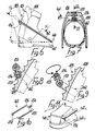
- the device 1 is composed of a pair of mutually identical rod-like elements, indicated by the reference numerals 2 and 3, each whereof is advantageously divided into a first half-element, indicated by the numerals 2a and 3a, and into a second half-element, indicated by the numerals 2b and 3b, idly pivoted to one another by means of a first small pivot 4.
- Each of said first half-elements 2a and 3a is composed of a first small rectilinear rod 5 one end whereof is idly pivoted, by means of a second small pivot 6, laterally with respect to the shell 7 at the tip region 8.
- a means for the adjustment of the flexing stroke of the front quarter 9 is rigidly associated with the other end of said first rod 5, said means consisting of a substantially cylindrical body 10, knurled externally and internally provided with a first axial cavity 11 and with a second axial cavity 12, said cavities being divided from one another by means of an axially foraminous dividing wall 13.
- a cylindrical helical compression spring 14 is arranged inside the first cavity 11 and interacts with a small plate 15 which is slideable within said cavity and is connected to the end of a second rectilinear rod 16 passes through the dividing wall 13, affecting the second cavity 12 and pivoted at its end to the second rod-like element.
- An adjustment ring 17 is associable with the second internally threaded axial cavity 12, and is provided with a complementarily threaded tang 18.
- Said ring 17 is provided with an axial seat 19 for the passage of the second ro16.
- planar surface 20 of the head of the ring 17 interacts in abutment engagement with the ends 21 of the front quarter 9 facing towards the region of the tip 8, said front quarter having, at the ends 21, a thickness sufficient to interact with the ring 17.
- Each of the second half-elements 2b and 3b is instead composed of a first rod 22, pivoted at one end to the second small rod 16, which has a slightly curved shaped in the direction of the upper end of the boot, its free end being threaded.
- the second half-element 2b and 3b is also composed of a second small rod 23 also provided with an end threaded in the opposite direction with respect to the end of the rod 22, said end cooperating with a means for the adjustment of their distance, consisting of a sleeve 24 which is internally threaded in a single direction.
- Each of the non-threaded ends of the second rod 23 which constitutes said second half-elements 2b and 3b is pivoted, by means of a third small pivot 25, to a locking-unlocking element consisting of a bar 26 having an L-shaped cross section.
- Said bar is arranged transversely with respect to the boot and affects the rear region 27 of the rear quarter 28.
- a set of teeth 29 is associated with said rear quarter at said region, and is arranged longitudinally with respect to said quarter, with which interacts an adapted cam 30 which projects from the flap of the bar 26 which can be arranged approximately perpendicular to said set of teeth 29. Said set of teeth is obtained monolithically with the quarter or is added thereto.
- the use of the device 1 is thus as follows: once the skier has put the boot on, he can operate a rough adjustment of the fastening between the front quarter 9 and the rear quarter 28 by arranging the cam 30 of the bar 26 on the set of teeth 29 at the point corresponding to the optimum tensioning.
- the arrangement of the bar 26 furthermore allows to fasten the quarters, also constituting a rest for the rear quarter which is useful most of all during the phases of extension while skiing.
- the skier can subsequently rotate the sleeve 24 appropriately and therefore move mutually closer or further apart the threaded ends of the first small rod 22 and of the second small rod 23.
- This adjustment allows to vary by the desired angle the inclination of the front quarter 9 with respect to the longitudinal axis of the shell.
- the device 1 furthermore allows to adjust the forward stroke of the front quarter 9: first of all it is possible to define a stroke limit by appropriately screwing or unscrewing the ring 17, the distance between the planar surface 20 of its head or that of the end 21 of the front quarter defining the free excursion which can be performed by the latter.
- a slot 31 is advantageously provided on the shell 7 and has the same longitudinal axis as said half-elements, within which said second small pivot 6 can idly slide.
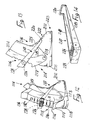
- Figures 6-10 illustrate a device 101 according to another aspect of the invention, consisting of a single essentially U-shaped rod-like element 102, at the ends of its arms there protruding two teeth 132 which are arranged mutually facing and insertable in adapted seats provided laterally with respect to the shell 107 at the tip region 108.
- a locking-unlocking element is associated with the bar 126 which affects the rear region 127 of the quarter 128 and consists of a pawl 133 idly pivoted at one end to said bar 126.
- the other end of the pawl is externally threaded and interacts with a complementarily threaded bush 134 the head 135 whereof is shaped complementarily with respect to the individual seats of the set of teeth 129 provided on the rear quarter 128.
- Said set of teeth preferably constitutes a single element with the quarter 128 and has a curved profile with its center in the pivoting point of the teeth 132. This allows to easily rotate the element 102 during the operations of opening and closure of the quarters, these operations being rapid and easy for the skier, since he merely has to place the bush 134 in the most appropriate point in order to achieve the optimum fastening of said quarters.
- Fig. 11 illustrates another embodiment of the rod-like element, consisting of a single element 102a, in the shape of a closed loop, the front end whereof is associable with a transverse seat 136 provided on the shell 107a at the tip region 108a.
- the reference numeral 201 indicates a rear-entry ski boot consisting of a shell 202 whereto are hinged a front quarter 203 and a rear quarter 204.
- a first transverse set of teeth 206 is provided on said rear quarter in the rear region 205, and ends with an arrestor tooth 207 which protrudes from said quarter 204 from its end adjacent to the heel 208 of the boot 201.
- a safety element is furthermore associated with the quarter 204: in fact, transverse slots 209 are provided at said first set of teeth 206 and constitute seats for teeth 210, slideable therein and protruding therefrom, rigidly associated with a rigid body 211 arranged inside the quarter 204 and pivoted thereto at an end proximate to the arrestor tooth 207.
- An operating button 212 is provided at the other end of said rigid body 211 and protrudes outside the quarter 204 through an adapted opening 213 provided proximate to the upper end 214 of said quarter 204.
- the teeth 210 normally protrude out of the slots 209 by virtue of the presence of a first elastically deformable element 215 interposed between said quarter 204 and said rigid body 211.
- the closure device structure 216 comprises a rod-like element 217 consisting of a single bracket, provided with two lateral wings 218 and 219 each arranged to one side of said quarters 203 and 204, and with two cross-members, a front one 220 and a rear one 221 which faces said set of teeth 206.
- the cross-member 220 can be interrupted at the middle region.
- the front cross-member 220 is shaped so as to be removably and selectively pivotable to a second set of teeth 222 formed transversely with respect to said shell 202 proximate to the region 223 of the tip of the boot 201.
- a preferably rubber-covered roller 224 is instead pivoted between the wings 218 and 219, adjacent to the rear cross-member 221, and has such a diameter as to be arrangeable between two adjacent teeth 210.
- the roller 224 though it rotates in contact with the set of teeth 206 and with the teeth 210 during the lifting or the lowering of the rear cross-member 221, causes no scraping and facilitates the sliding.
- the rear cross-member 221 furthermore constitutes a grip handle for the skier.
- a second elastically deformable element 225 cooperates with the elastic return of the front quarter 203 during the extension phase, and is interposable between said shell 202 and said front quarter 203.
- This second elastically deformable element 225 can consist of a longitudinal tab of the front quarter, or of a small rubber block or of another technically equivalent element.
- a closure device 216 initially entails the positioning of the front cross-member 220 at the second set of teeth 223.
- the roller 224 When the quarters are open, and therefore in the condition of maximum opening, the roller 224 abuts on the arrestor tooth 207 and thus prevents the excessive lowering of the rod-like element 217, thus allowing a good stride in walking.
- the skier positions the roller 224, raising, manually or by means of one other boot, the rear cross-member 221 along the set of teeth 206, so as to achieve the desired degree of fastening of said quarters.
- the presence of the teeth 210 allows to prevent any accidental uncoupling, intentional uncoupling being achieved by pressing the button 212 and then making said teeth 210 re-enter the slots 209.
- roller 224 furthermore allows not to subject to wear the rear region 205 of the quarter 204, the wings 218 and 219 conferring a considerable lateral rigidity to the boot.
- the rod-like element 217 as illustrated in fig. 17, can be provided with a portion 226 of the wings arranged at the inner lateral surface of the front quarter 203. This allows to improve the aesthetics of the boot 201 though keeping invariant the functional characteristics.
- Figures 18-20 illustrate another embodiment of the bracket 217, provided with the lateral wings 218a and 219a the rear ends whereof are associated with an adjustment block 221a which supports the roller 224a so as to allow the adjustment of its position along the wings of the bracket.
- the block 221a is provided with a framework 231a which rotatably supports a ring 233a; the ring 233a in turn engages a threaded bar 232a, arranged parallel to the lateral wings 218a and 219a of the brackets, so that by rotating the ring 233a the bar 232a is moved along a direction which is perpendicular to the rear surface of the quarter 204 provided with the set of teeth 206, the ring 233a being axially blocked.
- a roller 224a is connected to the end of the bar 232a facing the set of teeth 206, and consists of a supporting bar 235a fixed perpendicular to the bar 232a and supporting the rollers 236a.
- the supporting bar 235a is furthermore provided with its ends engaged in the slots 230 longitudinally provided on the wings 218a and 219a. In this manner, by rotating the ring 233a, the position of the roller 224a along the bracket 217 is adjusted, obtaining a further fine adjustment of the fastening of the quarters.
- the block 221a is furthermore provided with a covering shell 234a which has two symmetrical openings on the opposite sides, from which the ring 233a partially protrudes to allow its operation.
- the covering shell 234 is provided with an opening also at the roller 224a.
- the reference numeral 301 indicates a rear-entry ski boot, consisting of a shell 302 whereto are pivoted a front quarter 303 and a rear quarter 304, and provided with a closure and adjustment device according to another aspect of the invention.
- the rear quarter 304 is provided, on the rear region 305, with a transverse set of teeth 306.
- the device 307 comprises a rod-like element 308 consisting of a single essentially U-shaped bracket the wings 309 and 310 whereof are idly pivoted, proximate to the free ends, to the front quarter 303.
- Said rod-like element 308 is then provided with a planar base 311, which connects the wings 309 and 310, and faces the set of teeth 306 provided on the rear quarter.
- the rear region 305 of the latter is conveniently slightly curved to facilitate the rotation imparted to the rod-like element by the user.
- An essentially rectangular opening 312 is provided at said planar base 311 and acts as a seat for a lever 313.
- Said lever is idly pivoted, by means of a pivot 314, eccentrically and transversely with respect to the opening 312, the pivot 314 being adjacent to the end of the opening facing towards the heel of the boot.
- This locking-unlocking lever has its ends curved in opposite directions, to define, proximate to the pivot 314, a tooth 315, interacting with the set of teeth, and, at the opposite end, a grip element 316 which protrudes out of said planar base 311 and can be operated by the user.
- a movable tab adapted to allow the micrometric adjustment of its position with respect to the set of teeth 316.
- closure device 307 in fact entails that, once the shoe has been put on, the skier move the quarters close to one another, performing the fastening thereof by engaging the tooth 315 of the lever 313 in the selected point of the transverse set of teeth 306.
- the fastening pressure achieved is constant during flexing while skiing regardless of its value.
- the subsequent unlocking step is similarly rapid and simple; in fact, as is illustrated in figs. 22 and 23, it is sufficient to push outwards, for example by means of the other boot, the grip element 316, imparting a slight rotation to the lever 313 and therefore uncoupling the tooth 315 from the set of teeth 306.
- the smaller radius of rotation of the rod-like element due to its pivoting to the front quarter 303 and not to the shell 302, furthermore allows to obtain a stop during its lowering since it abuts with the rear quarter 304.
- FIGS. 25-27 illustrate a closure and adjustment device according to yet another aspect of the invention.
- a rear-entry boot 401 comprises a rear quarter 404 and a front quarter 403 connected to a shell 402.
- the rear quarter 404 is provided, at its rear outer surface, with a transverse set of teeth 406 which can be, for example, similar to the set of teeth described in detail in figures 15-16.
- the shell 402 is provided, on each side, with a hole 416 wherein is inserted a stud 407 for the pivoting of the front quarter 403 and of the rear quarter 404.
- a slot 405, preferably in the shape of an arc of a circle having its center at the hole 416 is provided above the hole 416 and slightly advanced on said shell 402.
- the front quarter 403 is provided with a hole 408 at the slot 405 which is such that, by rotating said quarter around the stud 407, the hole 408 is always superimposed on the slot 405.
- a connecting rivet 409 is inserted in the hole 408 and in the slot 405; advantageously, both sides of the boot are provided with the abovementioned slot 405, hole 408 and rivet 409 so that the ends of a substantially U-shaped rod-like element, or bracket 417 are connected to the two rivets 409.
- the bracket 417 consists of two lateral wings 419, of which only one is visible in figure 25, rearwardly joined by a rear cross-member 421.
- Each of the lateral wings 419 is provided, as described above, with the front end pivoted to the rivet 409, and is preferably arranged between the shell 402 and the front quarter 403 as illustrated in figure 26.
- the rear portion of the flap 419 is instead arranged outside the rear quarter 404 so that the bracket 417 rearwardly embraces said quarter 404, so that the rear cross-member 421 is arranged at the set of teeth 406.
- a roller 424 is provided at the cross-member 421 and is adapted to interact with the set of teeth 406 to adjust the closure of the quarters as previously described in detail, with particular reference to figures 12-17. Also in this case, it is possible to provide at the cross-member 421 a block for the adjustment of the excursion of the roller similar to the one described in figures 18-20.
- the degree of fastening of the quarters remains constant during flexing and, conversely, the angle of longitudinal inclination of the quarters with respect to the shell is independent from the degree of fastening of said quarters, in the case, for example, that between the front quarter and the shell a known inclination adjustment device is interposed.
- the front quarter is provided with a good return capacity during the extension step since it is directly coupled to the bracket.
- the invention achieves the intended aim and objects by providing a device which allows the adjustment of the closure of the quarters with an easy and rapid operation, as well as the simultaneous adjustment of their inclination and flexing stroke.
- the presence of a rigid element interconnecting the quarters and the shell confers a greater overall rigidity to the boot, thus obtaining a good resistance to lateral splayings of the front quarter and a good rear hold, as well as an excellent transmission of lateral stresses.
- the greater overall rigidity of the boot thus structured allows the possible reduction of the thicknesses of the shell and of the quarters, allowing a considerable reduction in weight.
- the structural simplicity of the device associates an appealing aesthetic aspect to simplicity and reliability in use.
- the materials employed, as well as the dimensions, may be any according to the requirements and to the state of the art.
Landscapes
- Health & Medical Sciences (AREA)
- General Health & Medical Sciences (AREA)
- Physical Education & Sports Medicine (AREA)
- Footwear And Its Accessory, Manufacturing Method And Apparatuses (AREA)
Priority Applications (1)
| Application Number | Priority Date | Filing Date | Title |
|---|---|---|---|
| AT87110876T ATE86084T1 (de) | 1986-08-01 | 1987-07-27 | Schliess- und einstellvorrichtung, insbesondere fuer schischuhe. |
Applications Claiming Priority (6)
| Application Number | Priority Date | Filing Date | Title |
|---|---|---|---|
| IT8256686 | 1986-08-01 | ||
| IT82566/86A IT1205519B (it) | 1986-08-01 | 1986-08-01 | Dispositivo di regolazione,particolarmente per scarponi da sci |
| IT5946486U IT208992Z2 (it) | 1986-10-29 | 1986-10-29 | Struttura di dispositivo di chiusura, particolarmente per scarponi da sci. |
| IT5946486U | 1986-10-29 | ||
| IT5946286U | 1986-10-29 | ||
| IT5946286U IT208990Z2 (it) | 1986-10-29 | 1986-10-29 | Struttura di dispositivo di chiusura, particolarmente per scarponi da sci. |
Related Child Applications (1)
| Application Number | Title | Priority Date | Filing Date |
|---|---|---|---|
| EP92112770.0 Division-Into | 1992-07-27 |
Publications (3)
| Publication Number | Publication Date |
|---|---|
| EP0255680A2 true EP0255680A2 (de) | 1988-02-10 |
| EP0255680A3 EP0255680A3 (en) | 1989-11-15 |
| EP0255680B1 EP0255680B1 (de) | 1993-03-03 |
Family
ID=27273734
Family Applications (2)
| Application Number | Title | Priority Date | Filing Date |
|---|---|---|---|
| EP87110876A Expired - Lifetime EP0255680B1 (de) | 1986-08-01 | 1987-07-27 | Schliess- und Einstellvorrichtung, insbesondere für Schischuhe |
| EP92112770A Withdrawn EP0512582A1 (de) | 1986-08-01 | 1987-07-27 | Schliess- und Einstellvorrichtung, insbesondere für Skischuh |
Family Applications After (1)
| Application Number | Title | Priority Date | Filing Date |
|---|---|---|---|
| EP92112770A Withdrawn EP0512582A1 (de) | 1986-08-01 | 1987-07-27 | Schliess- und Einstellvorrichtung, insbesondere für Skischuh |
Country Status (3)
| Country | Link |
|---|---|
| US (2) | US4882857A (de) |
| EP (2) | EP0255680B1 (de) |
| DE (1) | DE3784402T2 (de) |
Cited By (7)
| Publication number | Priority date | Publication date | Assignee | Title |
|---|---|---|---|---|
| FR2653310A1 (fr) * | 1989-10-24 | 1991-04-26 | Rossignol Sa | Chaussure de ski en matiere plastique. |
| FR2654903A1 (fr) * | 1989-11-24 | 1991-05-31 | Rossignol Sa | Chaussure de ski en matiere plastique. |
| FR2654904A1 (fr) * | 1989-11-24 | 1991-05-31 | Rossignol Sa | Chaussure de ski en matiere plastique. |
| FR2657504A1 (fr) * | 1990-01-26 | 1991-08-02 | Salomon Sa | Chaussure de ski alpin, a collier de serrage arriere articule. |
| FR2667224A1 (fr) * | 1990-10-02 | 1992-04-03 | Salomon Sa | Chaussure de ski a capot avant pivotant. |
| EP0477817A3 (en) * | 1990-09-27 | 1992-09-23 | Nordica S.P.A. | Rear support adjustment device, particularly for ski boots |
| EP0749702A1 (de) * | 1995-06-23 | 1996-12-27 | Shimano Inc. | Schuh für Snowboard |
Families Citing this family (11)
| Publication number | Priority date | Publication date | Assignee | Title |
|---|---|---|---|---|
| IT215388Z2 (it) * | 1988-11-28 | 1990-09-11 | Calzaturificio Tecnica | Perfezionamento nei dispositivi di regolazione di inclinazione negli scarponi da sci. |
| FR2657503B1 (fr) * | 1990-01-26 | 1994-09-23 | Salomon Sa | Chaussure de ski a entree arriere. |
| FR2674107A1 (fr) * | 1991-03-21 | 1992-09-25 | Salomon Sa | Chaussure de ski alpin a volet d'energie articule sur le bas de coque. |
| CH686162A5 (fr) * | 1992-01-29 | 1996-01-31 | Lange Int Sa | Chaussure de ski. |
| CH686484A5 (fr) * | 1992-08-07 | 1996-04-15 | Lange Int Sa | Chaussure de ski en matiere plastique. |
| AT400284B (de) * | 1992-10-23 | 1995-11-27 | Dynafit Skischuh Gmbh | Skischuh |
| FR2702935B1 (fr) * | 1993-03-24 | 1995-06-09 | Salomon Sa | Chaussure pour sport de glisse. |
| US5906058A (en) * | 1993-07-19 | 1999-05-25 | K-2 Corporation | Snowboard boot having a rigid strut |
| FR2736516B1 (fr) * | 1995-07-13 | 1997-08-14 | Rossignol Sa | Chaussure pour la pratique d'un sport de glisse |
| US6547596B1 (en) | 2000-05-30 | 2003-04-15 | Amphenol-Tuchel Electronics Gmbh | Filtered electrical connector with ferrite member and coil |
| EP2572599B1 (de) * | 2011-09-26 | 2015-04-22 | Rossignol Lange S.R.L. | Schale für Skischuh mit Spoiler |
Family Cites Families (19)
| Publication number | Priority date | Publication date | Assignee | Title |
|---|---|---|---|---|
| DE2108711A1 (de) * | 1971-02-24 | 1972-09-07 | Dr Justus Rieker & Co, 7200 Tutt lingen | Im Giessverfahren hergestellter Sport schuh, insbesondere Skischuh |
| JPS4955453A (de) * | 1972-09-28 | 1974-05-29 | ||
| FR2266468A1 (en) * | 1974-04-03 | 1975-10-31 | Trappeur | Ski boot with adjustable upper part - has rack on ankle receiving fasteners on upper part |
| DE2522968A1 (de) * | 1975-05-23 | 1977-01-20 | Josef Lederer | Skistiefel |
| FR2330345A1 (fr) * | 1975-11-04 | 1977-06-03 | Trappeur | Chaussure de ski perfectionnee |
| DE2805943A1 (de) * | 1978-02-13 | 1979-08-16 | Hermann Kastinger | Skistiefel |
| US4199879A (en) * | 1978-08-15 | 1980-04-29 | Wegeng Wendell A | Safety ski boot structure |
| DE2907163C3 (de) * | 1979-02-23 | 1981-10-29 | Etablissements François Salomon et Fils, 74000 Annecy, Haute-Savoie | Skischuh |
| FR2488807A2 (fr) * | 1979-09-12 | 1982-02-26 | Bataille Jean | Systeme de maintien du pied et de la jambe, applique aux sports de montagne |
| DE3174525D1 (en) * | 1980-12-02 | 1986-06-05 | Nordica Spa | Device for controlling the flex of ski boots |
| DE3247515A1 (de) * | 1982-07-19 | 1984-01-19 | Josef 8069 Jetzendorf Lederer | Schischuh |
| CH645002A5 (de) * | 1983-02-23 | 1984-09-14 | Raichle Sportschuh Ag | Skischuh. |
| AT385635B (de) * | 1983-06-01 | 1988-04-25 | Koeflach Sportgeraete Gmbh | Schuh, insbesondere schischuh |
| IT8422279V0 (it) * | 1984-06-13 | 1984-06-13 | Nordica Spa | Scarpone da sci particolarmente ad entrata posteriore con dispositivo di chiusura e di bloccaggio del piede. |
| FR2583270B1 (fr) * | 1985-06-12 | 1987-09-25 | Salomon Sa | Chaussure de ski alpin |
| IT209388Z2 (it) * | 1986-01-13 | 1988-10-05 | Nordica Spa | Regolatore di appoggio per gambali di scarponi da sci. |
| IT1190085B (it) * | 1986-04-09 | 1988-02-10 | Nordica Spa | Scarpone da sci ad entrata posteriore con dispositivo di chiusura e regolazione della flessibilita' |
| US4785555A (en) * | 1986-09-04 | 1988-11-22 | Nordica S.P.A. | Foot securing device, particularly for ski boots |
| IT209286Z2 (it) * | 1986-09-08 | 1988-09-20 | Nordica Spa | Dispositivo per la regolazione del grado di flessibilita' ed inclinazione, particolarmente per scarponi da sci. |
-
1987
- 1987-07-27 EP EP87110876A patent/EP0255680B1/de not_active Expired - Lifetime
- 1987-07-27 EP EP92112770A patent/EP0512582A1/de not_active Withdrawn
- 1987-07-27 DE DE8787110876T patent/DE3784402T2/de not_active Expired - Fee Related
- 1987-07-29 US US07/078,986 patent/US4882857A/en not_active Expired - Fee Related
-
1989
- 1989-11-16 US US07/436,849 patent/US4944100A/en not_active Expired - Fee Related
Cited By (10)
| Publication number | Priority date | Publication date | Assignee | Title |
|---|---|---|---|---|
| FR2653310A1 (fr) * | 1989-10-24 | 1991-04-26 | Rossignol Sa | Chaussure de ski en matiere plastique. |
| FR2654903A1 (fr) * | 1989-11-24 | 1991-05-31 | Rossignol Sa | Chaussure de ski en matiere plastique. |
| FR2654904A1 (fr) * | 1989-11-24 | 1991-05-31 | Rossignol Sa | Chaussure de ski en matiere plastique. |
| EP0430821A1 (de) * | 1989-11-24 | 1991-06-05 | Skis Rossignol S.A. | Skischuh aus Kunststoff |
| FR2657504A1 (fr) * | 1990-01-26 | 1991-08-02 | Salomon Sa | Chaussure de ski alpin, a collier de serrage arriere articule. |
| US5203098A (en) * | 1990-01-26 | 1993-04-20 | Salomon S.A. | Alpine ski boot with side latching apparatus |
| EP0477817A3 (en) * | 1990-09-27 | 1992-09-23 | Nordica S.P.A. | Rear support adjustment device, particularly for ski boots |
| FR2667224A1 (fr) * | 1990-10-02 | 1992-04-03 | Salomon Sa | Chaussure de ski a capot avant pivotant. |
| EP0479123A1 (de) * | 1990-10-02 | 1992-04-08 | Salomon S.A. | Skischuhe mit schwenkbarem Vorderschaft |
| EP0749702A1 (de) * | 1995-06-23 | 1996-12-27 | Shimano Inc. | Schuh für Snowboard |
Also Published As
| Publication number | Publication date |
|---|---|
| EP0255680A3 (en) | 1989-11-15 |
| US4882857A (en) | 1989-11-28 |
| EP0512582A1 (de) | 1992-11-11 |
| DE3784402T2 (de) | 1993-06-17 |
| US4944100A (en) | 1990-07-31 |
| DE3784402D1 (de) | 1993-04-08 |
| EP0255680B1 (de) | 1993-03-03 |
Similar Documents
| Publication | Publication Date | Title |
|---|---|---|
| EP0255680A2 (de) | Schliess- und Einstellvorrichtung, insbesondere für Schischuhe | |
| US7877902B2 (en) | Footwear with variable configuration heel | |
| US4519150A (en) | Ski boot | |
| US6547261B2 (en) | Adjustment device, particularly for adjusting the size of an in-line roller skate | |
| US20020174568A1 (en) | Footwear fit system | |
| US4864743A (en) | Heel blocking device for ski boot | |
| US4934075A (en) | Ski boot with angular position adjustment | |
| JPS61172502A (ja) | スキ−靴 | |
| JP2005501632A (ja) | 改良伸張式靴及び靴構造体 | |
| EP1142614A1 (de) | Grösseneinstellbarer einspuriger Rollschuh | |
| US4133119A (en) | Ski boot | |
| JP2012522548A (ja) | リアエントリー式の非対称な脚支持材を有するスノーボードバインディング | |
| EP0307745B1 (de) | Schischuh mit Fersenhalterung | |
| EP0945080A1 (de) | Hebelverschluss für Sportschuhe | |
| US20040107605A1 (en) | Sports shoe | |
| EP3687330B1 (de) | Skischuh | |
| US20040094917A1 (en) | Adjustment device, particularly for adjusting the length of a skate | |
| JPH0218842B2 (de) | ||
| US4700496A (en) | Boot, in particular ski boot, with a monolithic structure | |
| US5062226A (en) | Heel securing device, particularly for ski boots | |
| US5046269A (en) | Device for adjusting the flexibility in a ski boot | |
| EP0477817A2 (de) | Einstellvorrichtung für hintere Abstützung, insbesondere für Skischuhe | |
| EP0132743A1 (de) | Skischuh mit hinterem Eingang mit eingebauter Vorrichtung zur Regelung der Biegsamkeit | |
| JPH0370502A (ja) | 特にスキー靴用のたわみ調整装置 | |
| EP0241840A2 (de) | Skistiefel mit Vorrichtung zum Verändern der Biegsamkeit |
Legal Events
| Date | Code | Title | Description |
|---|---|---|---|
| PUAI | Public reference made under article 153(3) epc to a published international application that has entered the european phase |
Free format text: ORIGINAL CODE: 0009012 |
|
| AK | Designated contracting states |
Kind code of ref document: A2 Designated state(s): AT CH DE FR IT LI |
|
| PUAL | Search report despatched |
Free format text: ORIGINAL CODE: 0009013 |
|
| AK | Designated contracting states |
Kind code of ref document: A3 Designated state(s): AT CH DE FR IT LI |
|
| 17P | Request for examination filed |
Effective date: 19891206 |
|
| RAP1 | Party data changed (applicant data changed or rights of an application transferred) |
Owner name: NORDICA S.P.A. |
|
| 17Q | First examination report despatched |
Effective date: 19910508 |
|
| GRAA | (expected) grant |
Free format text: ORIGINAL CODE: 0009210 |
|
| AK | Designated contracting states |
Kind code of ref document: B1 Designated state(s): AT CH DE FR IT LI |
|
| REF | Corresponds to: |
Ref document number: 86084 Country of ref document: AT Date of ref document: 19930315 Kind code of ref document: T |
|
| XX | Miscellaneous (additional remarks) |
Free format text: TEILANMELDUNG 92112770.0 EINGEREICHT AM 27/07/87. |
|
| REF | Corresponds to: |
Ref document number: 3784402 Country of ref document: DE Date of ref document: 19930408 |
|
| ITF | It: translation for a ep patent filed | ||
| ET | Fr: translation filed | ||
| PLBE | No opposition filed within time limit |
Free format text: ORIGINAL CODE: 0009261 |
|
| STAA | Information on the status of an ep patent application or granted ep patent |
Free format text: STATUS: NO OPPOSITION FILED WITHIN TIME LIMIT |
|
| 26N | No opposition filed | ||
| PGFP | Annual fee paid to national office [announced via postgrant information from national office to epo] |
Ref country code: FR Payment date: 19950622 Year of fee payment: 9 |
|
| PGFP | Annual fee paid to national office [announced via postgrant information from national office to epo] |
Ref country code: AT Payment date: 19950718 Year of fee payment: 9 |
|
| PGFP | Annual fee paid to national office [announced via postgrant information from national office to epo] |
Ref country code: CH Payment date: 19950727 Year of fee payment: 9 |
|
| PGFP | Annual fee paid to national office [announced via postgrant information from national office to epo] |
Ref country code: DE Payment date: 19950921 Year of fee payment: 9 |
|
| PG25 | Lapsed in a contracting state [announced via postgrant information from national office to epo] |
Ref country code: AT Effective date: 19960727 |
|
| PG25 | Lapsed in a contracting state [announced via postgrant information from national office to epo] |
Ref country code: LI Effective date: 19960731 Ref country code: CH Effective date: 19960731 |
|
| REG | Reference to a national code |
Ref country code: CH Ref legal event code: PL |
|
| PG25 | Lapsed in a contracting state [announced via postgrant information from national office to epo] |
Ref country code: FR Effective date: 19970328 |
|
| PG25 | Lapsed in a contracting state [announced via postgrant information from national office to epo] |
Ref country code: DE Effective date: 19970402 |
|
| REG | Reference to a national code |
Ref country code: FR Ref legal event code: ST |
|
| PG25 | Lapsed in a contracting state [announced via postgrant information from national office to epo] |
Ref country code: IT Free format text: LAPSE BECAUSE OF NON-PAYMENT OF DUE FEES Effective date: 20050727 |