EP0255776A2 - Steuervorrichtung für Geschosse - Google Patents
Steuervorrichtung für Geschosse Download PDFInfo
- Publication number
- EP0255776A2 EP0255776A2 EP87306646A EP87306646A EP0255776A2 EP 0255776 A2 EP0255776 A2 EP 0255776A2 EP 87306646 A EP87306646 A EP 87306646A EP 87306646 A EP87306646 A EP 87306646A EP 0255776 A2 EP0255776 A2 EP 0255776A2
- Authority
- EP
- European Patent Office
- Prior art keywords
- nozzle
- projectile
- control means
- gas
- thrust
- Prior art date
- Legal status (The legal status is an assumption and is not a legal conclusion. Google has not performed a legal analysis and makes no representation as to the accuracy of the status listed.)
- Granted
Links
Images


Classifications
-
- F—MECHANICAL ENGINEERING; LIGHTING; HEATING; WEAPONS; BLASTING
- F42—AMMUNITION; BLASTING
- F42B—EXPLOSIVE CHARGES, e.g. FOR BLASTING, FIREWORKS, AMMUNITION
- F42B10/00—Means for influencing, e.g. improving, the aerodynamic properties of projectiles or missiles; Arrangements on projectiles or missiles for stabilising, steering, range-reducing, range-increasing or fall-retarding
- F42B10/60—Steering arrangements
- F42B10/66—Steering by varying intensity or direction of thrust
- F42B10/663—Steering by varying intensity or direction of thrust using a plurality of transversally acting auxiliary nozzles, which are opened or closed by valves
Definitions
- This invention relates to guidance apparatus for projectiles, especially gun shells but also missiles having an on-board propulsion unit such as a solid propellant motor.
- the trajectory of a given gun-shell is determined by the attitude of the gun upon firing and, once fired, it follows a ballistic trajectory. It is, however, advantageous if the trajectory can be varied as desired, as in the case of, for example, guided missiles, so as to improve accuracy particularly where the target is moving.
- guidance apparatus adapted to be mounted on a projectile for guiding the projectile during flight, the apparatus comprising:-
- the position from which the gas discharges to vary the trajectory of the projectile may be substantially stationary.
- a projectile for example a gun shell, including such guidance apparatus.
- the apparatus would be mounted on the projectile so that the axis of rotation of the nozzle coincides with the longitudinal axis of the projectile.
- the trajectory of such a projectile may therefore be varied as desired by the transmission of appropriate signals to the control means of the apparatus during flight.
- the projectile may be a spinning or a non-spinning projectile.
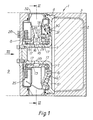
- the apparatus designated generally by reference numeral 1 includes a cast double base propellant charge 2 housed in a chamber 3 which is sealingly joined to a nozzle assembly by a screw-threaded joint 4.
- the nozzle assembly comprises a base 5 which constitutes the forward closure for the chamber 3, the base 5 containing a part annular recess which houses a part-annular igniter 6 of pyrotechnic material for the propellant charge 2.
- the igniter 6 is initiated by an electrically fired primer 6 ⁇ .
- the nose section 9 houses, inter alia, a seeker unit 10 ( Figure 4) and its associated electronic equipment (not shown).
- the tubular member 7, during operation of the apparatus 1, ducts gas from the burning charge 2 to the nozzle assembly, as described in more detail below.
- the nozzle assembly further comprises an annular member 13 which defines a frusto-conical nozzle 14 having a choke 11 and an inlet 15 which communicates with an annular recess 16 formed in the bore of the member 13.
- the member 13 is rotatably mounted on the tubular member 7 by two dry bearings 17.
- Four equi-spaced radial holes 18 connect the bore of the member 7 with the recess 16 and hence with the inlet 15 of the nozzle thereby providing a pathway for the flow of pressurised gas from the chamber 3 to the nozzle 14.
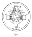
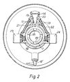
- the nozzle 14 is provided with a pair of opposed ports 19, 20 that serve, as described below, to inject jets of gas into the nozzle 14.
- the ports 19, 20 are arranged in the plane that contains the longitudinal axis of the nozzle 14 and that is perpendicular to the longitudinal axis of the tubular member 7, ie in the plane of rotation of the nozzle 14 about the axis of the member 7.
- the ports 19, 20 are connected to the annular recess 16, via respective small diameter pipes 21, 22 and respective on/off solenoid valves 23, 24 all of which are mounted on the member 13.
- a small proportion of gas generated by the propellant charge 2 is therefore injected through the port 19 or 20 into the main gas stream in the nozzle 14.
- the injected gas streams serve to establish shock waves within the nozzle, which in turn create rotational and braking thrust components, as the case may be, as is described below.
- the usual magnetic field-producing coils of the solenoid valves 23, 24 are electrically connected by leads 23 ⁇ , 24 ⁇ (Fig 3) to a slip-ring assembly 25 bolted to the member 13.
- the slip ring assembly 25 is additionally associated with a potentiometer 26 ( Figure 4) and a tachogenerator 27 ( Figure 4) to provide nozzle orientation data and nozzle rotational speed data respectively to a control unit 12 ( Figure 4) via a set of brushes 28 mounted on the bulkhead 8.
- a disengageable detent 29 is provided to lock the member 13 against rotation during storage, transit, gun launch and (where desired) the initial flight period of the projectile. Irreversible release of the detent 29 is effected by a spring-loaded actuator 30 in response to build-up of gas pressure communicated to the actuator 30 through a small bore 31.
- a protective plastic sleeve 32 is provided; on ignition of the charge 2, the hot gas issuing from the rotating nozzle 14 will quickly destroy the sleeve 32.
- the sleeve 32 could be removed prior to loading the projectile into the gun.
- the apparatus 1 operates as follows: Upon launch of the projectile from the gun, or at a predetermined time thereafter, the propellant charge 2 is ignited by the igniter 6 in response to an electrical current fed from the control unit 12 to the primer 6 ⁇ . Gas generated by the charge 2 therefore issues from the nozzle 14 via its inlet 15; also the detent 29 is released. At the same time, the solenoid valve 23 is de-energised, and therefore opened, by the control unit 12 via the slip ring assembly 25, whereas the solenoid valve 24 remains energised and therefore closed. A jet of gas is thereby injected into the nozzle 14 through the port 19 (Fig 2).
- the trajectory of the projectile will require at least one correction during flight and such correction or corrections are instigated by a seeker unit 10 that is "locked" onto the target.
- the seeker unit 10 senses that a trajectory correction is required.
- the seeker unit 10 transmits to the control unit 12 data signals reflecting the change that is required in terms of the radial thrust vector required (ie with the nozzle 14 substantially stationary) and its duration.
- the control unit 12 is fed with information from the potentiometer 26 and the tachogenerator 27.
- the control unit 12 is thereby provided with data giving, at one and the same instant, the actual angular position and rotational speed of the nozzle 14 and also its required stationary orientation and duration in that orientation.
- the control unit 12 then de-energises the solenoid valve 23 and energises the solenoid valve 24. Accordingly, injection of gas through the port 19 ceases and injection of gas through the opposite port 20 commences, thereby creating a thrust component that rapidly brakes rotation of the nozzle 14 until it assumes the required, substantially stationary orientation as indicated by the potentiometer 26.
- the nozzle 14 maintains that orientation for the required period of time, during which both valves 23, 24 are arranged to be energised and thus closed, and the necessary change of trajectory is thereby imparted to the projectile.
- the nozzle 14 re-assumes its continuously rotating mode unless and until a further change in the trajectory, as signalled by the seeker unit 10, is required.
- the nozzle is, in its normal rotating mode, moving at relatively high angular velocity, and partly because the response times of the control unit etc might be too slow, it is possible that, during the braking step, the nozzle 14 will "overshoot" the required angular orientation.
- This may be readily dealt with by the control unit 12 during the braking step alternately reversing the modes of the solenoid valves 23, 24 thereby alternately reversing the direction of the thrust component until the nozzle 14 more or less comes to rest in the required orientation.
- a like operation may be effected to correct any drift from that orientation that might occur during the trajectory alteration.
- control unit 12 it is desirable to limit the angular velocity of the nozzle during its normal, continuously rotating mode and this may be effected by the control unit 12 from time to time, in response to an excessive angular velocity as indicated by the tachogenerator 27, appropriately actuating the relevant valve to exert a temporary braking effect.
- apparatus of the invention could be used to guide missiles of the type having an on-board propulsion unit, for example a gas-generating solid propellant motor, in which case some of the gas generated by that propellant motor could be ducted to the guidance apparatus instead of there being a separate source such as the charge 2.
Landscapes
- Physics & Mathematics (AREA)
- Fluid Mechanics (AREA)
- Engineering & Computer Science (AREA)
- General Engineering & Computer Science (AREA)
- Aiming, Guidance, Guns With A Light Source, Armor, Camouflage, And Targets (AREA)
Applications Claiming Priority (2)
| Application Number | Priority Date | Filing Date | Title |
|---|---|---|---|
| GB868618510A GB8618510D0 (en) | 1986-07-29 | 1986-07-29 | Guidance apparatus for projectiles |
| GB8618510 | 1986-07-29 |
Publications (3)
| Publication Number | Publication Date |
|---|---|
| EP0255776A2 true EP0255776A2 (de) | 1988-02-10 |
| EP0255776A3 EP0255776A3 (en) | 1988-12-21 |
| EP0255776B1 EP0255776B1 (de) | 1992-12-09 |
Family
ID=10601892
Family Applications (1)
| Application Number | Title | Priority Date | Filing Date |
|---|---|---|---|
| EP87306646A Expired EP0255776B1 (de) | 1986-07-29 | 1987-07-28 | Steuervorrichtung für Geschosse |
Country Status (4)
| Country | Link |
|---|---|
| US (1) | US4763857A (de) |
| EP (1) | EP0255776B1 (de) |
| DE (1) | DE3782985T2 (de) |
| GB (1) | GB8618510D0 (de) |
Cited By (3)
| Publication number | Priority date | Publication date | Assignee | Title |
|---|---|---|---|---|
| FR2656083A1 (fr) * | 1989-12-18 | 1991-06-21 | Serat | Perfectionnements apportes aux projectiles agissant en survol ou au devant de la cible. |
| FR2753432A1 (fr) * | 1996-08-29 | 1998-03-20 | Matra Bae Dynamics Uk Ltd | Mecanisme a organe de poussee pour la commande d'attitude d'un corps volant |
| US5755401A (en) * | 1995-10-31 | 1998-05-26 | Thiokol Corporation | Missile diverter integration method and system |
Families Citing this family (8)
| Publication number | Priority date | Publication date | Assignee | Title |
|---|---|---|---|---|
| US5024395A (en) * | 1987-01-27 | 1991-06-18 | Messerschmitt Bolkow-Blohm Gmbh | Stepping mechanism for rotary motions |
| US4967982A (en) * | 1988-11-07 | 1990-11-06 | General Dynamics Corp., Pomona Division | Lateral thruster for missiles |
| DE4408085C2 (de) * | 1994-03-10 | 1999-08-12 | Rheinmetall W & M Gmbh | Vorrichtung zur Lenkung eines nicht um seine Längsachse rotierenden Flugkörpers |
| US5647558A (en) * | 1995-02-14 | 1997-07-15 | Bofors Ab | Method and apparatus for radial thrust trajectory correction of a ballistic projectile |
| US6758437B1 (en) * | 1997-02-07 | 2004-07-06 | Mcdonnell Douglas Corporation | Rocket engine nacelle |
| US8319162B2 (en) | 2008-12-08 | 2012-11-27 | Raytheon Company | Steerable spin-stabilized projectile and method |
| WO2011112668A1 (en) | 2010-03-10 | 2011-09-15 | Bae Systems Information And Electronic Systems Integration Inc. | Tail thruster control for projectiles |
| IL271483A (en) * | 2019-12-16 | 2021-06-30 | Shilat Optronics Ltd | A guided weapon system with low accuracy at night |
Family Cites Families (15)
| Publication number | Priority date | Publication date | Assignee | Title |
|---|---|---|---|---|
| US3058449A (en) * | 1959-03-02 | 1962-10-16 | Thompson Ramo Wooldridge Inc | Rocket engine control |
| US3090198A (en) * | 1960-11-17 | 1963-05-21 | Gen Motors Corp | Swivel nozzle control |
| US3165282A (en) * | 1962-02-07 | 1965-01-12 | Chrysler Corp | Pneumatic missile guidance system |
| US3270505A (en) * | 1964-10-21 | 1966-09-06 | Norman L Crabill | Control system for rocket vehicles |
| DE2846372C2 (de) * | 1978-10-25 | 1985-11-21 | Rheinmetall GmbH, 4000 Düsseldorf | Geschoß mit radialgerichteten Steuerdüsen zur Endphasenlenkung |
| DE2952181A1 (de) * | 1979-12-22 | 1981-07-16 | Dornier Gmbh, 7990 Friedrichshafen | Einrichtung zum steuern von flugkoerpern o.dgl., insbesondere zur rollsteuerung |
| DE3108231A1 (de) * | 1981-03-05 | 1982-09-23 | Messerschmitt-Bölkow-Blohm GmbH, 8000 München | Lenkflugkoerper |
| EP0069440A3 (de) * | 1981-04-16 | 1983-03-16 | Normalair-Garrett (Holdings) Limited | Einrichtung zum Erzeugen eines Gas-Schubkraft |
| FR2504085A1 (fr) * | 1981-04-21 | 1982-10-22 | Thomson Brandt | Dispositif de pilotage par jets de gaz et projectile comprenant un tel dispositif |
| FR2508414B1 (fr) * | 1981-06-30 | 1985-06-07 | Thomson Brandt | Dispositif de pilotage par jets de gaz pour engin guide |
| JPS60501366A (ja) * | 1983-01-20 | 1985-08-22 | ローラル・エアロスペイス・コーポレイション | 誘導ミサイルのためのラム空気燃焼式操舵装置 |
| DE3317583C2 (de) * | 1983-05-13 | 1986-01-23 | Messerschmitt-Bölkow-Blohm GmbH, 8012 Ottobrunn | Vorrichtung mit einer von einer Treibmittelquelle versorgten Düsenanordnung |
| DE3332415A1 (de) * | 1983-09-08 | 1985-03-28 | Messerschmitt-Bölkow-Blohm GmbH, 8012 Ottobrunn | Steuerbares stroemungsumlenksystem |
| DE3429798C1 (de) * | 1984-08-13 | 1985-12-12 | Messerschmitt-Bölkow-Blohm GmbH, 8012 Ottobrunn | Vorrichtung zur Korrektur der Flugbahn eines Geschosses |
| DE3519892C2 (de) * | 1985-06-04 | 1987-04-23 | Messerschmitt-Bölkow-Blohm GmbH, 8012 Ottobrunn | Brems- und Freigabevorrichtung für einen Drehdüsenkörper zur Lenkung eines Flugkörpers |
-
1986
- 1986-07-29 GB GB868618510A patent/GB8618510D0/en active Pending
-
1987
- 1987-07-28 DE DE8787306646T patent/DE3782985T2/de not_active Expired - Fee Related
- 1987-07-28 EP EP87306646A patent/EP0255776B1/de not_active Expired
- 1987-07-28 US US07/078,849 patent/US4763857A/en not_active Expired - Lifetime
Cited By (4)
| Publication number | Priority date | Publication date | Assignee | Title |
|---|---|---|---|---|
| FR2656083A1 (fr) * | 1989-12-18 | 1991-06-21 | Serat | Perfectionnements apportes aux projectiles agissant en survol ou au devant de la cible. |
| EP0434475A1 (de) * | 1989-12-18 | 1991-06-26 | Societe D'etudes, De Realisations Et D'applications Techniques (S.E.R.A.T.) | Vorrichtung zur Korrektur der Flugbahn eines Geschosses |
| US5755401A (en) * | 1995-10-31 | 1998-05-26 | Thiokol Corporation | Missile diverter integration method and system |
| FR2753432A1 (fr) * | 1996-08-29 | 1998-03-20 | Matra Bae Dynamics Uk Ltd | Mecanisme a organe de poussee pour la commande d'attitude d'un corps volant |
Also Published As
| Publication number | Publication date |
|---|---|
| DE3782985T2 (de) | 1993-04-08 |
| EP0255776B1 (de) | 1992-12-09 |
| EP0255776A3 (en) | 1988-12-21 |
| US4763857A (en) | 1988-08-16 |
| GB8618510D0 (en) | 1986-12-17 |
| DE3782985D1 (de) | 1993-01-21 |
Similar Documents
| Publication | Publication Date | Title |
|---|---|---|
| US7947938B2 (en) | Methods and apparatus for projectile guidance | |
| US4017040A (en) | Steerable extraction rocket | |
| TW319825B (de) | ||
| US4763857A (en) | Guidance apparatus for projectiles | |
| US5129604A (en) | Lateral thrust assembly for missiles | |
| US4573648A (en) | Ram air combustion steering system for a guided missile | |
| US3167016A (en) | Rocket propelled missile | |
| GB1102625A (en) | Stabilisation and guidance device for sounding rockets and rocket-propelled ballistic vehicles | |
| US3245350A (en) | Rocket propelled device for straightline payload transport | |
| US3000597A (en) | Rocket-propelled missile | |
| EP0135500B1 (de) | Lenkeinrichtung mittels stauluft an raketen | |
| US4817377A (en) | Head end control and steering system: using a forward end maneuvering gas generator | |
| EP0694155B1 (de) | Verfahren und vorrichtung zur übertragung von einem gewünschten bewegungsmuster an einem fliegenden gefechtskopf | |
| US3754725A (en) | Auxiliary rocket apparatus for installation on a missile to impart a roll moment thereto | |
| RU2082946C1 (ru) | Исполнительная система старта и ориентации ракеты | |
| JPS62152998A (ja) | 誘導ミサイルのためのラム空気式操舵装置 | |
| US4003531A (en) | Reverse flow reaction control system | |
| AU2006228511B2 (en) | Steering system and method for a guided flying apparatus | |
| US4295617A (en) | Selectable drag brakes for rocket range control | |
| US3358559A (en) | Wire-guided projectile propelling system | |
| US10030951B2 (en) | Drag reduction system | |
| US6478250B1 (en) | Propulsive torque motor | |
| EP0140657A1 (de) | Abschussvorrichtung für Geschosse | |
| USH684H (en) | Vented in-tube burning rocket | |
| GB2089009A (en) | Blast Equalizer for a Gun fired Ramjet Projectile |
Legal Events
| Date | Code | Title | Description |
|---|---|---|---|
| PUAI | Public reference made under article 153(3) epc to a published international application that has entered the european phase |
Free format text: ORIGINAL CODE: 0009012 |
|
| AK | Designated contracting states |
Kind code of ref document: A2 Designated state(s): DE FR GB SE |
|
| PUAL | Search report despatched |
Free format text: ORIGINAL CODE: 0009013 |
|
| AK | Designated contracting states |
Kind code of ref document: A3 Designated state(s): DE FR GB SE |
|
| RAP1 | Party data changed (applicant data changed or rights of an application transferred) |
Owner name: ROYAL ORDNANCE PLC |
|
| 17P | Request for examination filed |
Effective date: 19890605 |
|
| 17Q | First examination report despatched |
Effective date: 19901126 |
|
| GRAA | (expected) grant |
Free format text: ORIGINAL CODE: 0009210 |
|
| AK | Designated contracting states |
Kind code of ref document: B1 Designated state(s): DE FR GB SE |
|
| ET | Fr: translation filed | ||
| REF | Corresponds to: |
Ref document number: 3782985 Country of ref document: DE Date of ref document: 19930121 |
|
| RAP2 | Party data changed (patent owner data changed or rights of a patent transferred) |
Owner name: ROYAL ORDNANCE PLC |
|
| PLBE | No opposition filed within time limit |
Free format text: ORIGINAL CODE: 0009261 |
|
| STAA | Information on the status of an ep patent application or granted ep patent |
Free format text: STATUS: NO OPPOSITION FILED WITHIN TIME LIMIT |
|
| 26N | No opposition filed | ||
| EAL | Se: european patent in force in sweden |
Ref document number: 87306646.8 |
|
| PGFP | Annual fee paid to national office [announced via postgrant information from national office to epo] |
Ref country code: SE Payment date: 20000620 Year of fee payment: 14 |
|
| PGFP | Annual fee paid to national office [announced via postgrant information from national office to epo] |
Ref country code: FR Payment date: 20000621 Year of fee payment: 14 |
|
| PGFP | Annual fee paid to national office [announced via postgrant information from national office to epo] |
Ref country code: GB Payment date: 20000622 Year of fee payment: 14 |
|
| PGFP | Annual fee paid to national office [announced via postgrant information from national office to epo] |
Ref country code: DE Payment date: 20000629 Year of fee payment: 14 |
|
| PG25 | Lapsed in a contracting state [announced via postgrant information from national office to epo] |
Ref country code: GB Free format text: LAPSE BECAUSE OF NON-PAYMENT OF DUE FEES Effective date: 20010728 |
|
| PG25 | Lapsed in a contracting state [announced via postgrant information from national office to epo] |
Ref country code: SE Free format text: LAPSE BECAUSE OF NON-PAYMENT OF DUE FEES Effective date: 20010729 |
|
| EUG | Se: european patent has lapsed |
Ref document number: 87306646.8 |
|
| GBPC | Gb: european patent ceased through non-payment of renewal fee |
Effective date: 20010728 |
|
| PG25 | Lapsed in a contracting state [announced via postgrant information from national office to epo] |
Ref country code: FR Free format text: LAPSE BECAUSE OF NON-PAYMENT OF DUE FEES Effective date: 20020329 |
|
| PG25 | Lapsed in a contracting state [announced via postgrant information from national office to epo] |
Ref country code: DE Free format text: LAPSE BECAUSE OF NON-PAYMENT OF DUE FEES Effective date: 20020501 |
|
| REG | Reference to a national code |
Ref country code: FR Ref legal event code: ST |