EP0255855A2 - Entraînement à ressort accumulé pour appareils de commutation électrique - Google Patents
Entraînement à ressort accumulé pour appareils de commutation électrique Download PDFInfo
- Publication number
- EP0255855A2 EP0255855A2 EP87106723A EP87106723A EP0255855A2 EP 0255855 A2 EP0255855 A2 EP 0255855A2 EP 87106723 A EP87106723 A EP 87106723A EP 87106723 A EP87106723 A EP 87106723A EP 0255855 A2 EP0255855 A2 EP 0255855A2
- Authority
- EP
- European Patent Office
- Prior art keywords
- spring
- locking
- carrier shaft
- disk
- pawl
- Prior art date
- Legal status (The legal status is an assumption and is not a legal conclusion. Google has not performed a legal analysis and makes no representation as to the accuracy of the status listed.)
- Granted
Links
Images


Classifications
-
- H—ELECTRICITY
- H01—ELECTRIC ELEMENTS
- H01H—ELECTRIC SWITCHES; RELAYS; SELECTORS; EMERGENCY PROTECTIVE DEVICES
- H01H3/00—Mechanisms for operating contacts
- H01H3/22—Power arrangements internal to the switch for operating the driving mechanism
- H01H3/30—Power arrangements internal to the switch for operating the driving mechanism using spring motor
- H01H3/3047—Power arrangements internal to the switch for operating the driving mechanism using spring motor adapted for operation of a three-position switch, e.g. on-off-earth
-
- H—ELECTRICITY
- H01—ELECTRIC ELEMENTS
- H01H—ELECTRIC SWITCHES; RELAYS; SELECTORS; EMERGENCY PROTECTIVE DEVICES
- H01H3/00—Mechanisms for operating contacts
- H01H3/22—Power arrangements internal to the switch for operating the driving mechanism
- H01H3/30—Power arrangements internal to the switch for operating the driving mechanism using spring motor
- H01H3/3042—Power arrangements internal to the switch for operating the driving mechanism using spring motor using a torsion spring
Definitions
- the invention relates to a spring-loaded drive for electrical switching devices, in particular for switch disconnectors with an additional grounding position in addition to the on and off position, consisting of a base plate intended for attachment to the respective switch frame, a carrier shaft that can be connected to the associated switch shaft, one between the carrier shaft and a spring arrangement which can be pivoted by means of a plug-in lever and a locking unit for the carrier shaft which interacts with detachable pawls.
- the object of the present invention is to design a spring-loaded actuator of the type specified at the outset in such a way that it can be manufactured inexpensively, enables simple assembly and has at least three switch positions, so that switch disconnectors of the type disclosed in German patent application P 35 15 203 described type can be operated.
- the spring-loaded drive according to the invention should be able to be equipped, in particular retrofitted, with a controllable blocking device, which enables the switch to be pretensioned in the off position, so that the drive can be used as a transformer switch drive.
- the spring arrangement consists of a coaxial to the carrier shaft arranged torsion spring that the cooperating with a spring end support member is formed by a rotatably mounted on the carrier shaft, sleeve-shaped part and this sleeve-shaped part is fixedly connected to a control disk, that the other end of the torsion spring is supported on a driver connected to the carrier shaft that the driver is firmly connected to the locking unit designed as a disc, and that this locking disc has a pair of locking surfaces on its circumference, into which two pawls of a pair of ratchet levers or one pawl of two adjacent pairs of ratchet levers fall, depending on the rotation, in the different switching positions the control disc are detachable.
- the spring-loaded actuator according to the invention is particularly suitable for the SF6 switch-disconnector with three switching positions described in patent application P 35 15 203, the respective switching angle being 72 °. However, it is also possible to implement three further switching positions by attaching a third latch set.
- a disk serving to indicate the switch position is fixedly connected to the carrier shaft via a rigid intermediate carrier, thereby ensuring a direct transfer of the switch position to the position indicator, ie avoiding any deflection.
- An embodiment variant of the invention which is suitable as a transformer switch with an extended operating state "cocked for off” compared to a cable switch, is characterized in that the detachable pawl blocking the locking disk during the transition from the on position to the off position is assigned a releasable locking member is that allows only a partial lifting of the pawl into a release position blocked only by the locking member, and that the control disk has a locking support surface which, together with a locking lever biased in the switched-on position against the control disk, the control disk and thus the support bracket which tensions the torsion spring Condition holds.
- the conversion or retrofitting to the transformer switch drive in accordance with these additional features is carried out by attaching additional components which are merely screwed on, all the fastening points and functional surfaces already being present in the basic drive corresponding to the cable switch drive.
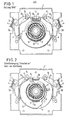
- FIG. 1 The schematic front view of a spring-loaded actuator in its basic configuration according to FIG. 1 shows a base plate 1 which can be connected directly to the respective switch frame or via damping elements, on which two axially opposite two pawls 2a, 2b; 2c, 2d are stored.
- compression springs 4 supported on pawls the pairs of pawls biased towards a decrease in the angle they enclose.
- the drive shaft of the associated switch extends through an opening in the base plate and is rotatably connected to a carrier shaft 6 of the spring-loaded drive.
- This carrier shaft 6 is designed as a pot shaft and is preferably connected to the switch shaft by means of a screw and possibly wedge connection.
- a torsion spring 8 is arranged on the carrier shaft 6 with the interposition of a bearing sleeve 7, in particular made of plastic.
- Support bracket 12 and thus control disk 11 can be pivoted clockwise and counterclockwise to perform switching movements by means of various plug levers 5.
- the locking disk 9, which is firmly connected to the carrier shaft 6, has locking surfaces 14, 15 which are connected to the pair of double pawls 2a, 2b; 2c, 2d interact in the different switching positions.
- the control disc 11 is provided with inclined surfaces x which, depending on the respective pivoting angle of the control disc 11, cause the pawls to be lifted out of the locking surfaces.
- the drive is actuated by means of a suitable plug lever via the support bracket 12 and the support plate 13 onto the control disk 11, which is turned clockwise with respect to the locking disk 9 in the switch-on direction, namely against the force of the torsion spring 8 caused by the arrangement of the drive plate 10 , and support tab 12 always claimed in the winding direction, ie is drawn.
- FIG. 2 shows the state of the spring-loaded drive according to FIG. 1 shortly before the switching on process.
- the spring 8 is already strongly tensioned by the rotation of the support plate 12 and support plate 13, but it is still held by the locking disk 9 and the driving plate 10 connected to it. Only a further rotation of the support bracket 12 and the support plate 13 causes the inclined surface x of the control disk 11 firmly connected to the support bracket 12 to engage the pawl 2b and cause this pawl 2b to be lifted, whereupon the locking disk 9 becomes free and thus due to the now released spring abruptly lags the locking disk 9 and thus the carrier shaft 6 until the rotational movement of the pawl 2c is stopped and the locking disk 9 is also locked in the opposite direction by the engagement of the spring-loaded pawl 2d.
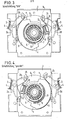
- Fig. 5 shows an axial section of the basic structure of the spring-loaded actuator according to the invention, in connection with additional elements that allow the use of this drive as a transformer switch, an additional switch position "biased towards the off” is possible.
- FIG. 5 shows the switch shaft 20 which extends through the base plate 1 and which is connected in a rotationally fixed manner to the carrier shaft 6 designed as a cup shaft.
- the carrier shaft 6 designed as a cup shaft.
- a central plug-in receptacle part 18 is inserted and fixed. This part is used to receive one of the two plug pins of the indicated lever 5 for switch actuation.
- the second plug pin of the plug lever 5 engages in an eccentrically arranged plug pin receptacle 19, which is designed as an elongated hole receptacle, in order to ensure the use of different levers for the switching-on process and the grounding process in connection with corresponding guide slots in a front plate.
- a major advantage of the drive according to the invention is that a disk 16 providing the switch position indicator can be connected directly to the carrier shaft 6, which is connected in a rotationally fixed manner to the switch shaft, via a simple intermediate carrier member 17 without deflections. This always ensures that the position indicator corresponds to the actual switch position and incorrect positions due to interference in transmission elements are excluded.
- Fig. 6 shows a sectional view along the line A-A in Fig. 5 and shows in particular the intended type of blocking the spring-loaded drive in the operating state "cocked for off".
- a locking arrangement is provided for the control disk 11 and thus for the support bracket which tensions the torsion spring 8, and on the other hand a device for preventing the pawl holding the locking disk 9 from being lifted is required.
- the device for blocking the control disk 11 consists of a locking support surface 21 which is arranged in this control disk 11 and which cooperates with a locking lever 22.
- This locking lever 22 is pivotable about an axis 26 provided on the base plate 1 and can be pretensioned in the direction of the locking disk 11 by means of a tensioning lever 23 and a tensioning spring 24.
- the tension spring 24 is fastened at one end to the lever 23 and at the other end to a bolt 25 which is fixedly connected to the pawl 2b and which can slide in an elongated hole 25 'of the tensioning lever 23. Contrary to the direction of attack of the force of the spring 24, the tensioning lever 23 is also loaded by a further spring fastened to the base plate 1.
- the spring 24 is stretched over the bolt 25 and the locking lever 22 is biased radially inward so that it can possibly engage with the locking support surface 21 .
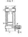
- a blocking device which consists of a pivotably mounted half-shaft 27, which is biased into the blocking position by means of a spring 30.
- Fig. 7 shows this half-wave arrangement 27, which interacts with the pawl 2d.
- the inclined surface x of the control disk 11 can only raise the pawl 2d to such an extent that it is transferred from its deep detent position into a self-releasing position, "but does not release the locking disk 9.
- the locking lever 22 is already pivoted inwards and can - when the tensioning movement is ended and the locking lever is returned somewhat clockwise again - come to rest on the locking support surface 21, as a result of which the torsion spring 8 remains tensioned.
- the spring-loaded drive according to the invention can largely be manufactured from stamped and bent parts and thus particularly inexpensively, without this having any losses in terms of functional reliability and service life.
Landscapes
- Driving Mechanisms And Operating Circuits Of Arc-Extinguishing High-Tension Switches (AREA)
- Mechanisms For Operating Contacts (AREA)
- Transmission Devices (AREA)
- Electrostatic Separation (AREA)
Priority Applications (1)
| Application Number | Priority Date | Filing Date | Title |
|---|---|---|---|
| AT87106723T ATE73574T1 (de) | 1986-08-05 | 1987-05-08 | Federspeicher-antrieb fuer elektrische schaltgeraete. |
Applications Claiming Priority (2)
| Application Number | Priority Date | Filing Date | Title |
|---|---|---|---|
| DE3626526 | 1986-08-05 | ||
| DE19863626526 DE3626526A1 (de) | 1986-08-05 | 1986-08-05 | Federspeicher-antrieb fuer elektrische schaltgeraete |
Publications (3)
| Publication Number | Publication Date |
|---|---|
| EP0255855A2 true EP0255855A2 (fr) | 1988-02-17 |
| EP0255855A3 EP0255855A3 (en) | 1989-04-26 |
| EP0255855B1 EP0255855B1 (fr) | 1992-03-11 |
Family
ID=6306750
Family Applications (1)
| Application Number | Title | Priority Date | Filing Date |
|---|---|---|---|
| EP87106723A Expired - Lifetime EP0255855B1 (fr) | 1986-08-05 | 1987-05-08 | Entraînement à ressort accumulé pour appareils de commutation électrique |
Country Status (4)
| Country | Link |
|---|---|
| EP (1) | EP0255855B1 (fr) |
| AT (1) | ATE73574T1 (fr) |
| DE (2) | DE3626526A1 (fr) |
| ES (1) | ES2029808T3 (fr) |
Cited By (5)
| Publication number | Priority date | Publication date | Assignee | Title |
|---|---|---|---|---|
| EP0325745A3 (fr) * | 1988-01-26 | 1990-08-29 | Gec Alsthom T & D GmbH | Dispositif pour l'indication de position de commutation d'un sectionneur de coupure en charge multiposition |
| EP0400632A3 (fr) * | 1989-06-02 | 1992-05-20 | Gec Alsthom T & D GmbH | Entrainement rotatif à ressort accumulé |
| EP0482362A3 (en) * | 1990-10-26 | 1992-10-28 | Maschinenfabrik Reinhausen Gmbh | Spring energy accumulator for on-load tap changer in step-down transformers |
| EP0563848A1 (fr) * | 1992-04-01 | 1993-10-06 | Gec Alsthom T & D GmbH | Entrainement rotatif à ressort accumulateur |
| CN102360969A (zh) * | 2011-11-05 | 2012-02-22 | 永济新时速电机电器有限责任公司 | 带有锁定装置的动车牵引辅助变流器用接地开关 |
Families Citing this family (5)
| Publication number | Priority date | Publication date | Assignee | Title |
|---|---|---|---|---|
| DE3802371A1 (de) * | 1988-01-27 | 1989-08-10 | Concordia Sprecher Schalt | Vorrichtung zur betaetigung von lasttrennschaltern |
| DE202006012002U1 (de) * | 2006-08-03 | 2007-12-20 | Walter Kraus Gmbh | Antrieb für einen Schalter in Elektroanlagen |
| FR2941558A1 (fr) * | 2009-06-19 | 2010-07-30 | Areva T & D Sa | Dispositif de commande d'appareillage electrique moyenne ou haute tension, notamment de sectionneur de terre |
| AT512813B1 (de) | 2012-04-16 | 2023-01-15 | Alexander Benedict | Vorrichtung für einen Trennschalter |
| DE102012107900A1 (de) * | 2012-08-28 | 2014-03-06 | Maschinenfabrik Reinhausen Gmbh | Kraftspeicher für einen Laststufenschalter |
Family Cites Families (3)
| Publication number | Priority date | Publication date | Assignee | Title |
|---|---|---|---|---|
| NL270929A (fr) * | 1960-11-04 | |||
| DE1887788U (fr) * | 1963-12-06 | 1964-02-20 | ||
| DE3239839C1 (de) * | 1982-10-27 | 1984-03-01 | Siemens AG, 1000 Berlin und 8000 München | Antrieb fuer einen elektrischen Dreistellungsschalter |
-
1986
- 1986-08-05 DE DE19863626526 patent/DE3626526A1/de not_active Withdrawn
-
1987
- 1987-05-08 AT AT87106723T patent/ATE73574T1/de active
- 1987-05-08 ES ES198787106723T patent/ES2029808T3/es not_active Expired - Lifetime
- 1987-05-08 EP EP87106723A patent/EP0255855B1/fr not_active Expired - Lifetime
- 1987-05-08 DE DE8787106723T patent/DE3777278D1/de not_active Expired - Fee Related
Cited By (5)
| Publication number | Priority date | Publication date | Assignee | Title |
|---|---|---|---|---|
| EP0325745A3 (fr) * | 1988-01-26 | 1990-08-29 | Gec Alsthom T & D GmbH | Dispositif pour l'indication de position de commutation d'un sectionneur de coupure en charge multiposition |
| EP0400632A3 (fr) * | 1989-06-02 | 1992-05-20 | Gec Alsthom T & D GmbH | Entrainement rotatif à ressort accumulé |
| EP0482362A3 (en) * | 1990-10-26 | 1992-10-28 | Maschinenfabrik Reinhausen Gmbh | Spring energy accumulator for on-load tap changer in step-down transformers |
| EP0563848A1 (fr) * | 1992-04-01 | 1993-10-06 | Gec Alsthom T & D GmbH | Entrainement rotatif à ressort accumulateur |
| CN102360969A (zh) * | 2011-11-05 | 2012-02-22 | 永济新时速电机电器有限责任公司 | 带有锁定装置的动车牵引辅助变流器用接地开关 |
Also Published As
| Publication number | Publication date |
|---|---|
| EP0255855B1 (fr) | 1992-03-11 |
| DE3777278D1 (de) | 1992-04-16 |
| ATE73574T1 (de) | 1992-03-15 |
| EP0255855A3 (en) | 1989-04-26 |
| ES2029808T3 (es) | 1992-10-01 |
| DE3626526A1 (de) | 1988-02-11 |
Similar Documents
| Publication | Publication Date | Title |
|---|---|---|
| EP0653010B1 (fr) | Dispositif de blocage des portes d'un vehicule automobile | |
| EP0623942A1 (fr) | Codeur | |
| EP0255855B1 (fr) | Entraînement à ressort accumulé pour appareils de commutation électrique | |
| EP0466287B1 (fr) | Disjoncteur avec un dispositif d'encliquetage indépendant du contact mobile | |
| DE4009503C2 (fr) | ||
| CH594279A5 (en) | Toggle drive unit for medium voltage switch - has symmetrical double spring which reduces bearing load and gives compact construction | |
| EP0279045A2 (fr) | Entraînement universel | |
| WO1998034256A2 (fr) | Appareil de commutation avec position de declenchement du mecanisme de verrouillage | |
| EP0508041B1 (fr) | Commande de commutation pour appareils électriques à moyenne tension | |
| DE19717236C2 (de) | Elektrisches Schaltgerät | |
| EP0563848B1 (fr) | Entrainement rotatif à ressort accumulateur | |
| WO2000045402A1 (fr) | Interrupteur a pression et a tirage | |
| EP0630035B1 (fr) | Interrupteur auxiliaire et de signalisation pour appareils interrupteurs de protection | |
| DE19839252B4 (de) | Schaltmechanismus für Schutzschalter | |
| WO1993025784A1 (fr) | Actionneur | |
| WO2004040727A2 (fr) | Disjoncteur | |
| DE2511804C2 (de) | Vorrichtung zur Betätigung elektrischer Schaltgeräte | |
| DE3107721C2 (de) | Sprungantriebsvorrichtung für ein elektrisches Schaltgerät, inbesondere für einen Mittelspannungs-Lasttrennschalter | |
| DE69804403T2 (de) | Antrieb für einen Dreistellungsschalter oder Dreistellungslastschalter | |
| EP0710969A1 (fr) | Dispositif verrouillable entraîné manuellement pour appareils de commutation blindés | |
| DE3203956C2 (de) | Sprungantriebsvorrichtung für ein elektrisches Schaltgerät | |
| DE69113179T2 (de) | Betätigungsmechanismus mit Trennvorrichtung für elektrischen Schalter. | |
| DE3114727A1 (de) | Federantrieb fuer elektrische schaltgeraete | |
| EP0400632A2 (fr) | Entrainement rotatif à ressort accumulé | |
| EP0688031B1 (fr) | Interrupteur de puissance à organe de signalisation de l'état d'un accumulateur d'énergie |
Legal Events
| Date | Code | Title | Description |
|---|---|---|---|
| PUAI | Public reference made under article 153(3) epc to a published international application that has entered the european phase |
Free format text: ORIGINAL CODE: 0009012 |
|
| AK | Designated contracting states |
Kind code of ref document: A2 Designated state(s): AT CH DE ES FR LI |
|
| PUAL | Search report despatched |
Free format text: ORIGINAL CODE: 0009013 |
|
| AK | Designated contracting states |
Kind code of ref document: A3 Designated state(s): AT CH DE ES FR LI |
|
| 17P | Request for examination filed |
Effective date: 19891024 |
|
| 17Q | First examination report despatched |
Effective date: 19910314 |
|
| GRAA | (expected) grant |
Free format text: ORIGINAL CODE: 0009210 |
|
| RAP1 | Party data changed (applicant data changed or rights of an application transferred) |
Owner name: CONCORDIA SPRECHER ENERGIE GMBH |
|
| AK | Designated contracting states |
Kind code of ref document: B1 Designated state(s): AT CH DE ES FR LI |
|
| REF | Corresponds to: |
Ref document number: 73574 Country of ref document: AT Date of ref document: 19920315 Kind code of ref document: T |
|
| REF | Corresponds to: |
Ref document number: 3777278 Country of ref document: DE Date of ref document: 19920416 |
|
| ET | Fr: translation filed | ||
| REG | Reference to a national code |
Ref country code: ES Ref legal event code: FG2A Ref document number: 2029808 Country of ref document: ES Kind code of ref document: T3 |
|
| PLBE | No opposition filed within time limit |
Free format text: ORIGINAL CODE: 0009261 |
|
| STAA | Information on the status of an ep patent application or granted ep patent |
Free format text: STATUS: NO OPPOSITION FILED WITHIN TIME LIMIT |
|
| 26N | No opposition filed | ||
| PGFP | Annual fee paid to national office [announced via postgrant information from national office to epo] |
Ref country code: FR Payment date: 19930517 Year of fee payment: 7 |
|
| PGFP | Annual fee paid to national office [announced via postgrant information from national office to epo] |
Ref country code: ES Payment date: 19930519 Year of fee payment: 7 |
|
| PGFP | Annual fee paid to national office [announced via postgrant information from national office to epo] |
Ref country code: AT Payment date: 19930526 Year of fee payment: 7 |
|
| PGFP | Annual fee paid to national office [announced via postgrant information from national office to epo] |
Ref country code: CH Payment date: 19930618 Year of fee payment: 7 |
|
| PGFP | Annual fee paid to national office [announced via postgrant information from national office to epo] |
Ref country code: DE Payment date: 19930628 Year of fee payment: 7 |
|
| PG25 | Lapsed in a contracting state [announced via postgrant information from national office to epo] |
Ref country code: AT Effective date: 19940508 |
|
| PG25 | Lapsed in a contracting state [announced via postgrant information from national office to epo] |
Ref country code: ES Free format text: LAPSE BECAUSE OF NON-PAYMENT OF DUE FEES Effective date: 19940509 |
|
| PG25 | Lapsed in a contracting state [announced via postgrant information from national office to epo] |
Ref country code: LI Effective date: 19940531 Ref country code: CH Effective date: 19940531 |
|
| PG25 | Lapsed in a contracting state [announced via postgrant information from national office to epo] |
Ref country code: FR Effective date: 19950131 |
|
| REG | Reference to a national code |
Ref country code: CH Ref legal event code: PL |
|
| PG25 | Lapsed in a contracting state [announced via postgrant information from national office to epo] |
Ref country code: DE Effective date: 19950201 |
|
| REG | Reference to a national code |
Ref country code: FR Ref legal event code: ST |
|
| REG | Reference to a national code |
Ref country code: ES Ref legal event code: FD2A Effective date: 19990301 |