EP0255873A2 - Dispositif pour ajuster et fixer le niveau d'un couvercle d'un toit de véhicule - Google Patents
Dispositif pour ajuster et fixer le niveau d'un couvercle d'un toit de véhicule Download PDFInfo
- Publication number
- EP0255873A2 EP0255873A2 EP87109775A EP87109775A EP0255873A2 EP 0255873 A2 EP0255873 A2 EP 0255873A2 EP 87109775 A EP87109775 A EP 87109775A EP 87109775 A EP87109775 A EP 87109775A EP 0255873 A2 EP0255873 A2 EP 0255873A2
- Authority
- EP
- European Patent Office
- Prior art keywords
- screw
- threaded
- roof
- adjusting screw
- guide frame
- Prior art date
- Legal status (The legal status is an assumption and is not a legal conclusion. Google has not performed a legal analysis and makes no representation as to the accuracy of the status listed.)
- Withdrawn
Links
Images
Classifications
-
- B—PERFORMING OPERATIONS; TRANSPORTING
- B60—VEHICLES IN GENERAL
- B60J—WINDOWS, WINDSCREENS, NON-FIXED ROOFS, DOORS, OR SIMILAR DEVICES FOR VEHICLES; REMOVABLE EXTERNAL PROTECTIVE COVERINGS SPECIALLY ADAPTED FOR VEHICLES
- B60J7/00—Non-fixed roofs; Roofs with movable panels, e.g. rotary sunroofs
- B60J7/02—Non-fixed roofs; Roofs with movable panels, e.g. rotary sunroofs of sliding type, e.g. comprising guide shoes
- B60J7/024—Non-fixed roofs; Roofs with movable panels, e.g. rotary sunroofs of sliding type, e.g. comprising guide shoes characterised by the height regulating mechanism of the sliding panel
Definitions
- the invention relates to a device for adjusting and fixing the height of an optional closing and at least partially releasing a roof section of a fixed roof surface of a vehicle with respect to the fixed roof surface, with a guide frame supporting the cover via a cover actuating device, which is under at least one the fixed roof surface fixed reinforcement part is arranged and connected to this height adjustable via screw members, the axis of which is perpendicular or almost perpendicular.
- the screw members each comprise a nut seated on the reinforcing part, into which a screw is screwed from below, which passes through the corresponding through holes of the guide frame and the reinforcing part and onto which between the guide frame and spacers in the required number and / or thickness are attached to the reinforcing part in order to adjust the height of the cover to the fixed roof surface.
- the height adjustment of the cover is relatively labor-intensive and time-consuming, since it has to be tried out or measured how many spacers are necessary in each case, and since these spacers then have to be introduced between the guide frame and the reinforcing part in a complicated manner.
- the invention specified in claim 1 has for its object to provide a device of the type mentioned, which further simplifies assembly and height adjustment and is also suitable for robot assembly.
- the screw members each have a threaded bushing attached to the guide frame with a continuous threaded opening, an adjusting screw provided with a through hole and screwed into the threaded opening of the threaded bushing, with its upper end projecting upward from the threaded bushing on the underside of the reinforcing part, and have a fastening screw inserted into the through hole of the adjusting screw, the end of which protrudes upward from the through hole of the adjusting screw into a threaded bore of the reinforcing part, the adjusting screw and the fastening screw being designed for adjustment from below.
- the height adjustment of the guide frame is carried out by correspondingly turning the adjusting screw which specifies the mutual height distance between the reinforcing part and the guide frame in that it is in threaded engagement with the threaded bushing of the guide frame and at the same time abuts against the underside of the reinforcing part.
- the arrangement is fixed by tightening the fastening screw, the fastening screw also serving to hang the guide frame on the reinforcing part in question.
- the height adjustment can be carried out precisely and continuously. Adjustment and mounting screws are easily accessible; for this reason and also because no additional elements, such as spacers or the like, need to be introduced, the device according to the invention is eminently suitable for robot assembly.
- the height adjustment screw members with additional fastening screw are known from DE-GM 17 64 070. Apart from the fact that these screw members are located between the roof-mounted guide rails of a sliding roof and the cover actuating device or between the cover and sliding pieces which can be displaced along the guide rails the fastening screw is screwed into a first threaded bushing which is attached to one of the mutually height-adjustable components and onto which a second threaded bushing is screwed which is supported against the other of the mutually height-adjustable components. The second threaded bushing must be turned to adjust the height. This is difficult because the second threaded bushing sits between the two components that are height-adjustable relative to one another and is consequently only accessible from the side.
- a reinforcing part is provided in a manner known per se, a roof reinforcing frame that surrounds the roof cutout at least at the front and laterally.
- the threaded bushings can expediently be attached to an outwardly projecting fastening flange of the guide frame. If the guide frame is made of plastic, threaded bushings, for example made of metal, can be embedded in the guide frame during its manufacture. If necessary, the threaded bushing can also be formed by the mounting frame of the guide flange itself.
- the arrangement is such that the adjusting screw projects downward with its lower end from the threaded bushing and carries a head for rotating the adjusting screw at its lower end.
- the lower end of the fastening screw can protrude downward from the through hole of the adjusting screw and a head can be used to turn the fastening screw at its lower end.
- the head of the adjusting screw advantageously has a downwardly opening recess for at least partially receiving the head of the fastening screw.
- a seal for mutually sealing the guide frame and the roof reinforcement frame is expediently arranged on the side of the screw members facing the roof cutout.
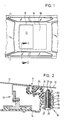
- a roof cutout 11 is provided in a fixed roof surface 10 of a motor vehicle.
- the roof cutout 11 can optionally be closed by means of a cover 12 or at least partially exposed.
- the cover 12 can be part of a sliding roof, a lifting roof, a sliding / lifting roof, a spoiler roof, a slatted roof, or the like in a known manner.
- the lid 12 is supported on a guide frame 14 by any lid actuating device of known type, which is only indicated schematically in FIG. 2 at 13.
- the roof cutout 11 is encompassed at least at the front and at the side by a roof reinforcement frame 15 seated under the fixed roof surface 10, which can be glued or spot welded to the fixed roof surface 10, for example.
- the guide frame 14 is connected to the roof reinforcement frame 15 in a height-adjustable manner by means of screw members designated overall by 16.
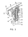
- the guide frame 14 has an outwardly projecting fastening flange 17, in which threaded bushings 18 forming parts of the screw members 16 are integrated at several locations distributed in the circumferential direction, for example in the case of a plastic guide frame, are embedded therein.
- Each threaded bushing 18 has a continuous threaded opening 19, the axis of which is perpendicular or almost vertical.
- An adjusting screw 20 is screwed into the threaded opening 19 and is provided with a through hole 21.
- the adjusting screw 20 is supported with its upper end projecting upward from the threaded bushing 18 on the underside of a flange 22 of the roof reinforcement frame 15.
- the flange 22 is vertically spaced below the fixed roof surface 10.
- a fastening screw 23 is inserted into the through hole 21.
- the end of the fastening screw 23 projecting upward from the through bore 21 is in screw engagement with a threaded bore 24 in the flange 22 of the roof reinforcement frame 15.
- the adjusting screw 20 carries a head 25 at its lower end projecting downward from the threaded bushing 18, while that from the Through hole 21 of the adjusting screw 20 projecting downward end of the fastening screw 23 is provided with a head 26.
- a recess 27 is formed, which opens downwards and which partially receives the head 26 of the tightened fastening screw 23 (FIG. 2).
- the guide frame 14 carries on the side of the fastening flange 17 facing the roof cutout 11 a seal 30 which, in the fully assembled state, bears sealingly against the roof reinforcement frame 15 from below.
- the cover 12 and the cover actuating device 13 can be completely mounted on the guide frame 14 and functionally tested.
- the upper ends of the adjusting screws 20 are expediently flush with the top of the threaded bushings 18 and the fastening flange 17.
- this unit can be mounted, for example, on compression springs in a mounting device be, which presses the mounting flange 17 of the guide frame 14 against the flange 22 of the roof reinforcement frame 15. The entire unit is pressed downwards against the spring pressure of the mounting device by screwing in the adjusting screws 20 by means of a tool indicated at 31 in FIG. 3.
- the cover 12 mounted on the guide frame 14 is thereby adjusted downwards.
- the fastening screws 23 are screwed into the threaded bores 24 of the flange 22 of the roof reinforcement frame 15 by means of a tool indicated at 32.
- the unit consisting of cover 12, cover actuation device 13 and guide frame 14 is connected to the roof reinforcement frame 15.
- the position of the adjusting screws 20 is fixed.
- the illustrated embodiment can be modified, inter alia, in such a way that the roof reinforcement frame is provided with threaded bushes or nuts for receiving the fastening screws 23. If necessary, the threaded bushings 18 can also be formed directly from the material of the fastening flange 17.
Landscapes
- Engineering & Computer Science (AREA)
- Mechanical Engineering (AREA)
- Body Structure For Vehicles (AREA)
- Fittings On The Vehicle Exterior For Carrying Loads, And Devices For Holding Or Mounting Articles (AREA)
Applications Claiming Priority (2)
| Application Number | Priority Date | Filing Date | Title |
|---|---|---|---|
| DE3626299 | 1986-08-02 | ||
| DE19863626299 DE3626299C1 (de) | 1986-08-02 | 1986-08-02 | Vorrichtung zum Einstellen und Fixieren der Hoehenlage eines Deckels eines Fahrzeugdaches |
Publications (2)
| Publication Number | Publication Date |
|---|---|
| EP0255873A2 true EP0255873A2 (fr) | 1988-02-17 |
| EP0255873A3 EP0255873A3 (fr) | 1988-04-06 |
Family
ID=6306621
Family Applications (1)
| Application Number | Title | Priority Date | Filing Date |
|---|---|---|---|
| EP87109775A Withdrawn EP0255873A3 (fr) | 1986-08-02 | 1987-07-07 | Dispositif pour ajuster et fixer le niveau d'un couvercle d'un toit de véhicule |
Country Status (2)
| Country | Link |
|---|---|
| EP (1) | EP0255873A3 (fr) |
| DE (1) | DE3626299C1 (fr) |
Cited By (1)
| Publication number | Priority date | Publication date | Assignee | Title |
|---|---|---|---|---|
| NL1004775C2 (nl) * | 1996-12-13 | 1998-06-17 | Inalfa Ind Bv | Werkwijze voor het monteren van een open-dakconstructie aan een voertuigdak, alsmede een dergelijke open-dakconstructie en daarin gebruikte bevestigingsmiddelen. |
Families Citing this family (3)
| Publication number | Priority date | Publication date | Assignee | Title |
|---|---|---|---|---|
| DE4108195C1 (en) * | 1991-03-14 | 1992-04-23 | Webasto Ag Fahrzeugtechnik, 8035 Stockdorf, De | Sliding and lifting vehicle roof - has height adjustment using screw between guide frame and reinforcement frame |
| DE4142267C1 (fr) * | 1991-12-20 | 1992-12-24 | Webasto Ag Fahrzeugtechnik, 8035 Stockdorf, De | |
| US6786537B2 (en) * | 2002-12-12 | 2004-09-07 | Arvinmeritor Technology, Llc | One piece plastic water management system for sunroof |
Family Cites Families (4)
| Publication number | Priority date | Publication date | Assignee | Title |
|---|---|---|---|---|
| DE949446C (de) * | 1954-02-19 | 1956-09-20 | Wilhelm Baier K G Webasto Werk | Verfahren zum Befestigen von Rahmen in Wandungsoeffnungen, insbesondere in horizontalen Wandungsoeffnungen von Fahrzeugen |
| DE1764070U (de) * | 1958-02-12 | 1958-03-27 | Hans Traugott Golde & Co G M B | Schiebedach fuer kraftfahrzeuge. |
| DE1161155B (de) * | 1958-08-21 | 1964-01-09 | Daimler Benz Ag | Dachausschnitt an Schiebedaechern, insbesondere von Kraftfahrzeugen |
| DE1505282A1 (de) * | 1965-10-15 | 1969-08-14 | Auto Union Gmbh | Einstellvorrichtung fuer einen Schiebedachdeckel |
-
1986
- 1986-08-02 DE DE19863626299 patent/DE3626299C1/de not_active Expired
-
1987
- 1987-07-07 EP EP87109775A patent/EP0255873A3/fr not_active Withdrawn
Cited By (1)
| Publication number | Priority date | Publication date | Assignee | Title |
|---|---|---|---|---|
| NL1004775C2 (nl) * | 1996-12-13 | 1998-06-17 | Inalfa Ind Bv | Werkwijze voor het monteren van een open-dakconstructie aan een voertuigdak, alsmede een dergelijke open-dakconstructie en daarin gebruikte bevestigingsmiddelen. |
Also Published As
| Publication number | Publication date |
|---|---|
| EP0255873A3 (fr) | 1988-04-06 |
| DE3626299C1 (de) | 1988-01-28 |
Similar Documents
| Publication | Publication Date | Title |
|---|---|---|
| DE19542109C2 (de) | Befestigungsanordnung einer Reling auf einem Fahrzeugdach | |
| DE4435008A1 (de) | Einstellvorrichtung für eine mit einer Fensterheberanordnung zusammenwirkende, rahmenlos ausgebildete Türfensterscheibe eines Kraftfahrzeuges | |
| EP0159001A2 (fr) | Elément support amortisseur à réglage de la hauteur | |
| CH668232A5 (de) | Tragvorrichtung fuer eine last. | |
| DE10213131C1 (de) | Scharnier für ein Kraftfahrzeug | |
| EP2180121A2 (fr) | Dispositif de fixation d'un capot en position | |
| DE60308364T2 (de) | Vorrichtung zur Seiteneinstellung eines Fensterhebers für Kraftfahrzeuge | |
| DE19528789C1 (de) | Verschlußanordnung für ein bewegliches Karosserieteil | |
| EP0255873A2 (fr) | Dispositif pour ajuster et fixer le niveau d'un couvercle d'un toit de véhicule | |
| DE4007391C2 (de) | Befestigungsflansch für eine Abdeckleiste | |
| CH675275A5 (de) | Beschlag fuer schiebetueren. | |
| DE3644492C2 (fr) | ||
| DE19811165B4 (de) | Positionierelement zur Ausrichtung von Karosserieteilen | |
| DE3229732C1 (de) | Scharnier | |
| DE3401550C2 (de) | Windabweiser für Fahrzeuge | |
| DE4142267C1 (fr) | ||
| EP0787880B1 (fr) | Dispositif de réglage de hauteur pour une finition en partie inférieure de portes ou de fenêtres | |
| DE19533157A1 (de) | Befestigungsanordnung einer Reling auf einem Fahrzeugdach | |
| EP0960760A1 (fr) | Dispositif de fixation pour une fenêtre de véhicule à moteur | |
| DE60213208T2 (de) | Befestigung eines öffnungsfähigen KFZ-Dachaufbaus | |
| DE4124528C1 (en) | Solid car roof with sun roof aperture - has threaded adjuster with two parts, effective in opposite directions via link | |
| DE102004038433A1 (de) | Verdeckkastendeckel für Kraftfahrzeuge | |
| DE3146907C2 (de) | Höheneinstellvorrichtung an einem Schiebedach für Kraftfahrzeuge | |
| DE8717745U1 (de) | Vorrichtung zur einstellbaren Befestigung eines Scharnierbandes (Tür, Fenster) an einer Stahlzarge | |
| DE4108195C1 (en) | Sliding and lifting vehicle roof - has height adjustment using screw between guide frame and reinforcement frame |
Legal Events
| Date | Code | Title | Description |
|---|---|---|---|
| PUAI | Public reference made under article 153(3) epc to a published international application that has entered the european phase |
Free format text: ORIGINAL CODE: 0009012 |
|
| PUAL | Search report despatched |
Free format text: ORIGINAL CODE: 0009013 |
|
| AK | Designated contracting states |
Kind code of ref document: A2 Designated state(s): DE FR GB NL SE |
|
| AK | Designated contracting states |
Kind code of ref document: A3 Designated state(s): DE FR GB NL SE |
|
| 17P | Request for examination filed |
Effective date: 19880510 |
|
| 17Q | First examination report despatched |
Effective date: 19890214 |
|
| STAA | Information on the status of an ep patent application or granted ep patent |
Free format text: STATUS: THE APPLICATION IS DEEMED TO BE WITHDRAWN |
|
| 18D | Application deemed to be withdrawn |
Effective date: 19890704 |
|
| RIN1 | Information on inventor provided before grant (corrected) |
Inventor name: IGEL, RICHARD Inventor name: SCHLEICHER, BERND |