EP0255910A2 - Skibindung - Google Patents
Skibindung Download PDFInfo
- Publication number
- EP0255910A2 EP0255910A2 EP87110887A EP87110887A EP0255910A2 EP 0255910 A2 EP0255910 A2 EP 0255910A2 EP 87110887 A EP87110887 A EP 87110887A EP 87110887 A EP87110887 A EP 87110887A EP 0255910 A2 EP0255910 A2 EP 0255910A2
- Authority
- EP
- European Patent Office
- Prior art keywords
- boot
- ski binding
- locking
- ski
- jaw
- Prior art date
- Legal status (The legal status is an assumption and is not a legal conclusion. Google has not performed a legal analysis and makes no representation as to the accuracy of the status listed.)
- Granted
Links
Images



Classifications
-
- A—HUMAN NECESSITIES
- A63—SPORTS; GAMES; AMUSEMENTS
- A63C—SKATES; SKIS; ROLLER SKATES; DESIGN OR LAYOUT OF COURTS, RINKS OR THE LIKE
- A63C9/00—Ski bindings
- A63C9/08—Ski bindings yieldable or self-releasing in the event of an accident, i.e. safety bindings
- A63C9/084—Ski bindings yieldable or self-releasing in the event of an accident, i.e. safety bindings with heel hold-downs, e.g. swingable
- A63C9/0844—Ski bindings yieldable or self-releasing in the event of an accident, i.e. safety bindings with heel hold-downs, e.g. swingable the body pivoting about a transverse axis
-
- A—HUMAN NECESSITIES
- A63—SPORTS; GAMES; AMUSEMENTS
- A63C—SKATES; SKIS; ROLLER SKATES; DESIGN OR LAYOUT OF COURTS, RINKS OR THE LIKE
- A63C7/00—Devices preventing skis from slipping back; Ski-stoppers or ski-brakes
- A63C7/10—Hinged stoppage blades attachable to the skis in such manner that these blades can be moved out of the operative position
- A63C7/1006—Ski-stoppers
- A63C7/1013—Ski-stoppers actuated by the boot
-
- A—HUMAN NECESSITIES
- A63—SPORTS; GAMES; AMUSEMENTS
- A63C—SKATES; SKIS; ROLLER SKATES; DESIGN OR LAYOUT OF COURTS, RINKS OR THE LIKE
- A63C9/00—Ski bindings
- A63C9/005—Ski bindings with means for adjusting the position of a shoe holder or of the complete binding relative to the ski
-
- A—HUMAN NECESSITIES
- A63—SPORTS; GAMES; AMUSEMENTS
- A63C—SKATES; SKIS; ROLLER SKATES; DESIGN OR LAYOUT OF COURTS, RINKS OR THE LIKE
- A63C9/00—Ski bindings
- A63C9/08—Ski bindings yieldable or self-releasing in the event of an accident, i.e. safety bindings
- A63C9/0805—Adjustment of the toe or heel holders; Indicators therefor
-
- A—HUMAN NECESSITIES
- A63—SPORTS; GAMES; AMUSEMENTS
- A63C—SKATES; SKIS; ROLLER SKATES; DESIGN OR LAYOUT OF COURTS, RINKS OR THE LIKE
- A63C9/00—Ski bindings
- A63C9/08—Ski bindings yieldable or self-releasing in the event of an accident, i.e. safety bindings
- A63C9/081—Ski bindings yieldable or self-releasing in the event of an accident, i.e. safety bindings with swivel sole-plate
-
- A—HUMAN NECESSITIES
- A63—SPORTS; GAMES; AMUSEMENTS
- A63C—SKATES; SKIS; ROLLER SKATES; DESIGN OR LAYOUT OF COURTS, RINKS OR THE LIKE
- A63C9/00—Ski bindings
- A63C9/08—Ski bindings yieldable or self-releasing in the event of an accident, i.e. safety bindings
- A63C9/084—Ski bindings yieldable or self-releasing in the event of an accident, i.e. safety bindings with heel hold-downs, e.g. swingable
- A63C9/0841—Ski bindings yieldable or self-releasing in the event of an accident, i.e. safety bindings with heel hold-downs, e.g. swingable with a single jaw
- A63C9/0842—Ski bindings yieldable or self-releasing in the event of an accident, i.e. safety bindings with heel hold-downs, e.g. swingable with a single jaw the jaw pivoting on the body or base about a transverse axis
-
- A—HUMAN NECESSITIES
- A63—SPORTS; GAMES; AMUSEMENTS
- A63C—SKATES; SKIS; ROLLER SKATES; DESIGN OR LAYOUT OF COURTS, RINKS OR THE LIKE
- A63C9/00—Ski bindings
- A63C9/08—Ski bindings yieldable or self-releasing in the event of an accident, i.e. safety bindings
- A63C9/084—Ski bindings yieldable or self-releasing in the event of an accident, i.e. safety bindings with heel hold-downs, e.g. swingable
- A63C9/0845—Ski bindings yieldable or self-releasing in the event of an accident, i.e. safety bindings with heel hold-downs, e.g. swingable the body or base or a jaw pivoting about a vertical axis, i.e. side release
-
- A—HUMAN NECESSITIES
- A63—SPORTS; GAMES; AMUSEMENTS
- A63C—SKATES; SKIS; ROLLER SKATES; DESIGN OR LAYOUT OF COURTS, RINKS OR THE LIKE
- A63C9/00—Ski bindings
- A63C9/08—Ski bindings yieldable or self-releasing in the event of an accident, i.e. safety bindings
- A63C9/084—Ski bindings yieldable or self-releasing in the event of an accident, i.e. safety bindings with heel hold-downs, e.g. swingable
- A63C9/0846—Details of the release or step-in mechanism
-
- A—HUMAN NECESSITIES
- A63—SPORTS; GAMES; AMUSEMENTS
- A63C—SKATES; SKIS; ROLLER SKATES; DESIGN OR LAYOUT OF COURTS, RINKS OR THE LIKE
- A63C9/00—Ski bindings
- A63C9/08—Ski bindings yieldable or self-releasing in the event of an accident, i.e. safety bindings
- A63C9/086—Ski bindings yieldable or self-releasing in the event of an accident, i.e. safety bindings using parts which are fixed on the shoe of the user and are releasable from the ski binding
Definitions
- the present invention relates to a ski binding particularly for downhill skis and to the related boot with reduced-length sole.
- ski bindings currently comprise a front binding device and a rear binding device, both made so as to allow, by cooperating with one another, small movements along the longitudinal axis of the ski so as to absorb any movements between the boot and the ski while skiing.
- the tip which is generally articulated so as to allow the uncoupling of the boot from the ski in case of an accidental fall of the skier, furthermore allows the recovery of any slight misalignments between the boot and the ski due to the stresses to which said ski is subject while it slides on the snow, said stresses not being, however, such as to exceed the critical release value.
- the rear binding device must finally allow a motion along an axis which is substantially vertical with respect to the ski in order to perform the possible uncoupling of the boot from the skin in the active safety phase while skiing, and furthermore cause the voluntary release from the ski and the resetting of the binding for a comfortable fitting of the boot.
- the structure of current bindings generally does not allow the interchangeability of boots thereon, since the variation of their distance, either closer or further apart, is extremely small, this implying, if an adaptation of the bindings, for example to a new model of boot, is required, the need to shift the coupling points of the bindings on the skis with a consequent formation of new holes wherein the retention screws of the bindings thereon are to be inserted.
- Boots used on these known couplings usually have a sole with a length which is greater than that of the upper of the boot, said sole protruding at the front and at the rear to allow the securing of the boot on the ski.
- the length of the sole in boots determines a rather difficult and tiring stride for the skier when walking, as well as an unnatural erect position when he is standing, this position increasing his fatigue especially when waiting for access to ski-lifts.
- the aim proposed by the present invention is to eliminate the disadvantages described above by providing a ski binding, particularly for downhill racing skis, and related boot with reduced-length sole which allows to combine, in a single device for the securing of the boot to the ski, the various functions which are currently provided, in downhill ski bindings, by means of a front binding and a rear binding.
- an important object of the invention is to provide a ski binding particularly for downhill racing skis which has an extremely simple and compact structure which leads to economy in manufacture.
- Still another object of the invention is to devise a ski binding, particularly for downhill skis, which has an extremely low weight so as to facilitate the control of the skis whereto it is connected.
- a further object of the invention is to provide a ski binding, particularly for downhill skis, and related boot with reduced-length sole, which allow, regardless of the boot sizes, the interchaneability between boot and binding.
- Not least object of the invention is to provide a boot with a reduced-length sole which facilitates the skier's stride in walking and avoids fatigue thereof during pauses and walks without skis.
- a ski binding particularly for downhill skis, comprising a front coupling element for a boot and a rear device for the removable locking of said boot, characterized in that said locking device comprises sliding elements for its translatory motion, against and due to, the biasing action of first elastic means, along the longitudinal axis of said ski and rotation elements for its oscillation, against and due to, the biasing action of second elastic means, around an axis which is substantially vertical with respect to said base plate, said sliding elements and said rotation elements acting independently and simultaneously with respect to one another.
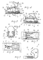
- the ski binding particularly for downhill skis, according to the invention, is generally indicated by the reference numeral 1, and comprises a base plate 2 associated with a ski 3 which is provided, towards the front, in an end portion thereof facing the tip of the ski, with an element 4 for the front coupling of the boot and, in a rear portion, with a device, generally indicated by the reference numeral 5 for the releasable locking of the boot on the ski.
- the locking device 5 combines in itself all the various functions which are currently assigned, in known bindings, to the tip element and to the heel element thereof.
- the locking device 5 comprises sliding elements, generally indicated by the reference numeral 6, for its translatory motion against and due to, the action of first elastic biasing means, and more precisely of a spring 7, along the longitudinal axis of the ski 3.
- the locking device 5 furthermore comprises rotation elements, generally indicated by the reference numeral 8, for its oscillation against and due to the action of second elastic biasing means, and more precisely of two springs 9, about an axis which is substantially vertical with respect to the base plate 2.
- rotation elements generally indicated by the reference numeral 8 for its oscillation against and due to the action of second elastic biasing means, and more precisely of two springs 9, about an axis which is substantially vertical with respect to the base plate 2.
- Each of said springs is also indicated by the numerals 9a and 9b.
- the sliding elements 6 and the rotation elements 8 act on the boot independently and/or simultaneously with respect to to one another, so as to allow, by means of only the rear locking device, a slight motion along the longitudinal axis of the ski to absorb small movements thereof with respect to the boot, and to allow, by rotation, the recovery of the skiing position after the stresses which cause the shift of the boot with respect to the ski, such stresses not exceeding the critical release value.
- the locking device along an axis which is vertical with respect to the ski, allows the uncoupling of the boot in the active safety phase while skiing and furthermore causes the voluntary release of the ski from the boot and the resetting of the binding for a comfortable fitting of the boot.
- the sliding elements 6 comprise two U-bolts 10a and 10b which are fixed, spaced apart, on the plate 2 to allow the sliding, below them and above the plate 2, of a slider 11 parallel to said plate 2, against and due to, the action of the spring 7 which is respectively associated, with its ends, on one side to an abutment 12, rigidly associated with the base plate 2, and on the other with the end 13 of the slider.
- the spring 7 can be conveniently calibrated according to the physical characteristics of the skier and also according to his skiing abilities by means of a screw 14 associable with the end 13 of the slider.
- the slider 11 rotatably supports, in a portion thereof comprised between the two U-bolts 10 the rotation elements 8.
- the rotation elements 8 comprise a bracket 15 wherefrom extends, on the part facing the guide 11, a pivot 16 rotatbly conncted thereto so as to allow the bracket to oscillate about the axis of said pivot and possibly simultaneously move together with the slider 11.
- two shoulders 17a and 17b extend vertically, and are parallel to one another and spaced so as to allow to arrange, partially between them, a jaw 18 for locking the boot to the ski.
- the jaw 18 is pivoted in two holes 19, respectively provided in the two shoulders 17a and 17b and can thus rotate partially within said mutually coaxial holes, in contrast with, and due to, the action of the two springs 9, which thus cooperate to keep the jaw in a stable position, furthermore controlling the grip force on the boot and therefore the control of the vertical uncoupling thereof from the ski.
- the use of the two springs 9, which are oscillable along planes mutually parallel and substantially perpendicular to the base plate 2 and parallel to the longitudinal axis of the ski, furthermore allow, as mentioned above, the rotation of the jaw to allow the elastic recovery of the skiing position or to allow the final lateral release.
- the springs 9 are provided, at their respective ends, with elements having a spherical head indicated by 20a and 20b, which are movably retained on one side by a terminal wall 21 which extends perpendicular from the base plate and on the opposite side slideably within two inclined seats, each indicated by the reference numeral 22, provided on the jaw 18 on its face directed towards the terminal wall 21.
- the inclined seats 22 extend on both the sides which are opposite with respect to the pivoting axis of the jaw 18 on the bracket 15 so that when the jaw is rotated in an opening position the spherical head elements 20 move, sliding within the seats 22, below the pivoting point of the jaw, moving closer to the guide 11 so as to provide a stroke limit for the rotation of the jaw, ensuring, at the same time, the position of the latter.
- the spherical head elements arrange themselves above the point of pivoting of the jaw to the bracket and therefore move away from the guide 11, providing the thrust force required for the engagement of the boot to the ski.
- the terminal wall 21 comprises a screw 23 which acts on a small plate 24 which is adapted to vary the calibration of the two springs 9 according to the weight of the skier and to the anti-uncoupling force which it is desired to provide in the binding also according to the skier's type of skiing.
- the locking jaw 18 is furthermore provided, on the side facing the plate 2, with a first expansion 25 adapted to allow its oscillation from a passive position to an active position of locking of the boot when the latter is pushed towards the ski by the user after having been engaged to the coupling element 4.
- the locking jaw is furthermore provided, on the opposite side with respect to the first expanded portion 25, with a second expanded portion 26 which engages in a region of the boot which is spaced apart from the base plate 2 and is arranged above the bracket 15 so that the engagement between the boot and the binding device is advantageously spaced from the sole of the boot, thus allowing a more effective transmission of the forces from the latter to the ski.
- the front coupling element 4, according to another aspect of the invention can for example comprise an element 27, oscillating against and due to, the biasing action of an elastic element 28 so as to provide the user with a further safety of front uncoupling in case of accidental fall.
- the boot 29 is provided, in the sole, with a recess 30, which is adapted to engage to the coupling element 4, which is always equidistant from the rear end of the sole of the boot regardless of the size thereof, thus ensuring the interchangeability between the boot and the binding.
- the fact of having a reduced-length sole considerably improves the stride of the skier, furthermore facilitating his walking.
- the front tip portion of the sole of the boot, indicated by 31 is arranged on a plane which is parallel but offset with respect to the plane defined by the remaining part of the sole, so as to reduce the forward inclination of the boot resting on the ground and to accordingly reduce the fatique of the skier during waits and walks without his skis on.
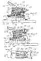
- Figures 10-12 illustrate a rear device for releasable locking according to another aspect of the invention, generally indicated by the reference numeral 105.
- the device 105 comprises a base plate 124, rigidly associated with a ski 103 in a known manner and slideably supporting a slider 121.
- the slider 121 can slide along a direction parallel to the longitudinal axis of the ski and is normally in abutment, towards the front, with a front locator element 124a of said base plate and is rearwardly opposed in its translatory motion by a spring 126 in abutment with a rear locator element 124b.
- the force opposed by the spring 126 is adjustable by means of a screw 127 in the manner described above.
- An assembly 122 is pivoted to the slider 121 by means of a pivot 120, and is oscillable along a horizontal and transverse axis with respect to the longitudinal axis of the ski.
- a jaw 128 is rotatably associated with the assembly 122 by means of a substantially vertical pivot 129; the jaw 128 thus grips the boot 29 in a manner which is substantially similar to what has been described above.
- the assembly 122 furthermore comprises at least two elastic elements which independently oppose the rotation of the jaw 128 and the oscillation of said assembly 122 with respect to the pivot 120.
- the two elastic elements advantageously consist of a first spring 132 and of a second spring 131 arranged parallel to one another and along a vertical plane; the cylindrical springs 131 and 132 furthermore have their axis substantially parallel to the longitudinal axis of the ski.
- the first spring 132 acts on the jaw 128 in the following manner: the spring 132 is provided with a front end in abutment with an element 133 slideable within the assembly 122 and acting on the jaw 128 by means of the tabs 133a and 133b.
- the rear end of the spring 132 abuts with a threaded cap 136 rigidly coupled to the assembly 122, and the jaw 128 thus acts, by rotating in any direction, on the tabs 133a and 133b longitudinally shifting the element 133 opposed, in this movement, by the spring 132.
- the second spring 131 is instead used to oppose the oscillation of the assembly 122, and therefore of the jaw 128, in the vertical direction.
- the spring 131 has its rear end in abutment with a threaded cap 137 rigidly associated with the assembly 122 and its front end in abutment with a cam 130 which is slideable within the assembly 122 in a direction substantially parallel to the longitudinal axis of the ski.
- the outer surface of the cam 130 is convex and cooperates with concave seat 121a provided in the slider 121 so that an anticlockwise rotation of the assembly 122, that is to say an upward movement of the jaw 128, is matched by a translatory motion of the cam 130 which occurs rearwards and is therefore opposed by the action of the spring 131.
- the action of the spring 131 by means of the threaded cap 137, the force required to open the rear coupling device 105 in the vertical direction in case of accidental fall is adjusted.
- a lever 123 is advantageously provided and pivoted to the slider 121 by means of the pivot 134 and connected to the assembly 122 by means of the pivot 135.
- an anticlockwise rotation about the pivot 134 is imparted to the lever, thus raising the pivot 135 and the assembly 122.
- FIG. 13-17 illustrate a rear coupling device according to yet another aspect of the invention, generally indicated by the reference numeral 205, comprising a base plate 204 fixed in a known manner to a ski 203 and slideably supporting a slider 201.
- the base plate 204 is provided with a front locator element 204a which acts as a front abutment for the slider 201, and with a rear locator element 204b which supports a spring 226 which opposes the rearward translatory motion of the slider.
- the force exerted by the spring 226 is adjustable by means of the screw 227 in the manner described above.
- An antifriction element 225 is advantageously interposed between the slider 201 and the plate 204 to facilitate the sliding of said slider.
- the slider 201 is provided, towards the front, with a support 218 for a jaw 208 adapted to couple to the rear part of a boot
- the jaw 208 is associated with the support 218 by means of a spherical articulation 209 so that it can rotate along axes which are perpendicular and transverse (with reference to the longitudinal axis of the ski).
- the jaw 208 is kept in the normal position of coupling of the boot by a releasable locking element comprising a box-like body 202 rigidly associated with the slider 201 rearwards with respect to the jaw 208.
- the box-like body 202 is hollow and has its front and rear ends open and respectively engaged by an axially slideable cylinder 212 and by a threaded cap 213. Inside the body 202, a helical spring 211 is provided with a first end in abutment with the interior of the threaded cap 213 and with a second end in abutment with the base 212a of the cylinder 212.
- the cylinder 212 is connected to a locking element 210 consisting of a cylindrical stem 215 arranged inside the body 202 and of a head 216 with a semicylindrical portion arranged outside said body. More precisely, the stem 215 is inserted in a central hole provided in the base 212a of the cylinder 212, while the head 216 abuts with said base 212a and at the same time engages a seat 217 provided on the jaw 208 and provided with a semicylindrical configuration corresponding to the configuration of the head 216.
- the rotations of the jaw 208 around the perpendicular and transverse axes are thus opposed by the action of the locking element 210 which is pushed in abutment to the seat 217 by the force of the spring 211.
- the force of the spring 211 is adjustable by rotating the threaded cap 213 which, for this purpose, is advantageously provided with a slit 228 engageable by a screwdriver or by a similar tool.
- a resetting lever 230 is advantageously provided pivoted to the slider 201 and acting on the jaw 208 so as to impart thereto a rotation around the transverse axis, uncoupling the head 216 of the locking element 210 from the seat 217.
- the slider 210 is provided with two lateral flaps 231 arranged at the box-like body 202; the lever 230 is pivoted to the lateral flaps 231 by means of pivots 232 and is provided with front tabs 233 associated with the rear region of the jaw 208.
- the head 216 engages the recess 229 provided on the jaw 208 in a portion adjacent to the seat 217 so that said jaw assumes a stable opening, or resetting, position.
- a ski-stopper 235 is associable to the base plate 204, and is pivoted to said plate in front of the jaw 208.
- the ski binding according to the invention is particularly advantageous in that it combines in only the rear locking device various functions which are currently, in known ski bindings, provided by means of the tip element and the heel element.
- the ski boot related to the ski binding besides allowing ease in walking for the skier, furthermore allows the interchaneability between boot and binding.
- the materials employed, as well as the dimensions, may be any according to the requirements and to the state of the art.
Landscapes
- Footwear And Its Accessory, Manufacturing Method And Apparatuses (AREA)
- Transition And Organic Metals Composition Catalysts For Addition Polymerization (AREA)
- Laminated Bodies (AREA)
- Phenolic Resins Or Amino Resins (AREA)
Priority Applications (1)
| Application Number | Priority Date | Filing Date | Title |
|---|---|---|---|
| AT87110887T ATE86134T1 (de) | 1986-08-04 | 1987-07-28 | Skibindung. |
Applications Claiming Priority (2)
| Application Number | Priority Date | Filing Date | Title |
|---|---|---|---|
| IT82567/86A IT1205520B (it) | 1986-08-04 | 1986-08-04 | Attacco da sci particolarmente per sci da discesa e relativo scarpone con suola a lunghezza ridotta |
| IT8256786 | 1986-08-04 |
Publications (3)
| Publication Number | Publication Date |
|---|---|
| EP0255910A2 true EP0255910A2 (de) | 1988-02-17 |
| EP0255910A3 EP0255910A3 (en) | 1989-10-11 |
| EP0255910B1 EP0255910B1 (de) | 1993-03-03 |
Family
ID=11318856
Family Applications (1)
| Application Number | Title | Priority Date | Filing Date |
|---|---|---|---|
| EP87110887A Expired - Lifetime EP0255910B1 (de) | 1986-08-04 | 1987-07-28 | Skibindung |
Country Status (5)
| Country | Link |
|---|---|
| EP (1) | EP0255910B1 (de) |
| JP (1) | JPS6340583A (de) |
| AT (1) | ATE86134T1 (de) |
| DE (1) | DE3784405T2 (de) |
| IT (1) | IT1205520B (de) |
Cited By (1)
| Publication number | Priority date | Publication date | Assignee | Title |
|---|---|---|---|---|
| US6554295B2 (en) | 2000-04-03 | 2003-04-29 | K-2 Corporation | Strapless toelock binding for snowboards |
Family Cites Families (5)
| Publication number | Priority date | Publication date | Assignee | Title |
|---|---|---|---|---|
| US3666280A (en) * | 1967-12-14 | 1972-05-30 | Smolka & Co Wiener Metall | Ski binding |
| DE2023169C2 (de) * | 1970-05-12 | 1982-07-22 | Hannes 8100 Garmisch-Partenkirchen Marker | Sicherheitsskibindung |
| AT370330B (de) * | 1978-07-07 | 1983-03-25 | Tyrolia Freizeitgeraete | Sicherheitsskibindung mit einem vorderbacken und einem fersenhalter |
| FR2470617A1 (fr) * | 1979-11-28 | 1981-06-12 | Salomon & Fils F | Dispositif de verrouillage pour fixations de securite de skis |
| CH654750A5 (fr) * | 1983-11-01 | 1986-03-14 | Haldemann Ag | Fixation de securite d'une chaussure sur un ski. |
-
1986
- 1986-08-04 IT IT82567/86A patent/IT1205520B/it active
-
1987
- 1987-07-28 AT AT87110887T patent/ATE86134T1/de not_active IP Right Cessation
- 1987-07-28 EP EP87110887A patent/EP0255910B1/de not_active Expired - Lifetime
- 1987-07-28 DE DE8787110887T patent/DE3784405T2/de not_active Expired - Fee Related
- 1987-07-31 JP JP62190536A patent/JPS6340583A/ja active Pending
Cited By (1)
| Publication number | Priority date | Publication date | Assignee | Title |
|---|---|---|---|---|
| US6554295B2 (en) | 2000-04-03 | 2003-04-29 | K-2 Corporation | Strapless toelock binding for snowboards |
Also Published As
| Publication number | Publication date |
|---|---|
| EP0255910B1 (de) | 1993-03-03 |
| IT1205520B (it) | 1989-03-23 |
| EP0255910A3 (en) | 1989-10-11 |
| ATE86134T1 (de) | 1993-03-15 |
| IT8682567A0 (it) | 1986-08-04 |
| DE3784405D1 (de) | 1993-04-08 |
| DE3784405T2 (de) | 1993-06-09 |
| JPS6340583A (ja) | 1988-02-20 |
Similar Documents
| Publication | Publication Date | Title |
|---|---|---|
| US5031341A (en) | Rear-entry ski boot | |
| US4761899A (en) | Ski boot | |
| US4367885A (en) | Ski binding | |
| US5518264A (en) | Free heel/anterior release ski binding | |
| US4230338A (en) | Safety ski binding | |
| EP0014892B1 (de) | Kombination von Skibindung und Skischuh | |
| EP0098881A4 (de) | Vorrichtung zur verbesserten kontrolle von skiern. | |
| US20030155742A1 (en) | Ski binding | |
| JPH01158902A (ja) | スキー靴の靴底 | |
| EP0229638A2 (de) | Einstellvorrichtung für die Stützen der Schaftoberteile von Schischuhen | |
| US4679815A (en) | Safety ski binding | |
| US4278269A (en) | Combined ski boot and safety binding | |
| US4182524A (en) | Safety ski binding | |
| NO341233B1 (no) | Anordning bestående av en skibinding og en skisko | |
| US4677771A (en) | Ski boot | |
| US6142503A (en) | Device for holding a boot on a snowboard | |
| US4404758A (en) | Skiing boot | |
| EP3687330B1 (de) | Skischuh | |
| US6450526B1 (en) | Suspended heel-piece for the safety binding of a ski | |
| US20130026736A1 (en) | Binding for the practice of skiing | |
| JPS5918044B2 (ja) | スキ−靴の前方傾斜調整装置 | |
| US5265901A (en) | Heel unit for ski bindings with automatic reset means | |
| US3942809A (en) | Safety ski binding | |
| EP0255910B1 (de) | Skibindung | |
| US6951347B2 (en) | Front binding for gliding-sports device |
Legal Events
| Date | Code | Title | Description |
|---|---|---|---|
| PUAI | Public reference made under article 153(3) epc to a published international application that has entered the european phase |
Free format text: ORIGINAL CODE: 0009012 |
|
| AK | Designated contracting states |
Kind code of ref document: A2 Designated state(s): AT CH DE FR IT LI |
|
| PUAL | Search report despatched |
Free format text: ORIGINAL CODE: 0009013 |
|
| AK | Designated contracting states |
Kind code of ref document: A3 Designated state(s): AT CH DE FR IT LI |
|
| 17P | Request for examination filed |
Effective date: 19891102 |
|
| RAP1 | Party data changed (applicant data changed or rights of an application transferred) |
Owner name: NORDICA S.P.A. |
|
| 17Q | First examination report despatched |
Effective date: 19910429 |
|
| GRAA | (expected) grant |
Free format text: ORIGINAL CODE: 0009210 |
|
| AK | Designated contracting states |
Kind code of ref document: B1 Designated state(s): AT CH DE FR IT LI |
|
| REF | Corresponds to: |
Ref document number: 86134 Country of ref document: AT Date of ref document: 19930315 Kind code of ref document: T |
|
| REF | Corresponds to: |
Ref document number: 3784405 Country of ref document: DE Date of ref document: 19930408 |
|
| ET | Fr: translation filed | ||
| ITF | It: translation for a ep patent filed | ||
| PG25 | Lapsed in a contracting state [announced via postgrant information from national office to epo] |
Ref country code: AT Effective date: 19930728 |
|
| PG25 | Lapsed in a contracting state [announced via postgrant information from national office to epo] |
Ref country code: LI Effective date: 19930731 Ref country code: CH Effective date: 19930731 |
|
| PLBE | No opposition filed within time limit |
Free format text: ORIGINAL CODE: 0009261 |
|
| STAA | Information on the status of an ep patent application or granted ep patent |
Free format text: STATUS: NO OPPOSITION FILED WITHIN TIME LIMIT |
|
| 26N | No opposition filed | ||
| PG25 | Lapsed in a contracting state [announced via postgrant information from national office to epo] |
Ref country code: FR Effective date: 19940331 |
|
| REG | Reference to a national code |
Ref country code: CH Ref legal event code: PL |
|
| PG25 | Lapsed in a contracting state [announced via postgrant information from national office to epo] |
Ref country code: DE Effective date: 19940401 |
|
| REG | Reference to a national code |
Ref country code: FR Ref legal event code: ST |
|
| PG25 | Lapsed in a contracting state [announced via postgrant information from national office to epo] |
Ref country code: IT Free format text: LAPSE BECAUSE OF NON-PAYMENT OF DUE FEES Effective date: 20050728 |