EP0255938A2 - Table d'opération, particulièrement pour le soin des accidentés - Google Patents
Table d'opération, particulièrement pour le soin des accidentés Download PDFInfo
- Publication number
- EP0255938A2 EP0255938A2 EP87111251A EP87111251A EP0255938A2 EP 0255938 A2 EP0255938 A2 EP 0255938A2 EP 87111251 A EP87111251 A EP 87111251A EP 87111251 A EP87111251 A EP 87111251A EP 0255938 A2 EP0255938 A2 EP 0255938A2
- Authority
- EP
- European Patent Office
- Prior art keywords
- table top
- axis
- operating table
- parallel
- table according
- Prior art date
- Legal status (The legal status is an assumption and is not a legal conclusion. Google has not performed a legal analysis and makes no representation as to the accuracy of the status listed.)
- Granted
Links
- 230000000149 penetrating effect Effects 0.000 claims description 2
- 238000001356 surgical procedure Methods 0.000 abstract 1
- 210000000689 upper leg Anatomy 0.000 description 3
- 235000004443 Ricinus communis Nutrition 0.000 description 2
- 240000000528 Ricinus communis Species 0.000 description 2
- 230000005540 biological transmission Effects 0.000 description 2
- 210000000245 forearm Anatomy 0.000 description 2
- 210000002414 leg Anatomy 0.000 description 2
- 206010017076 Fracture Diseases 0.000 description 1
- 208000031294 Upper limb fractures Diseases 0.000 description 1
- 230000001174 ascending effect Effects 0.000 description 1
- 230000007547 defect Effects 0.000 description 1
- 210000000629 knee joint Anatomy 0.000 description 1
- 239000000463 material Substances 0.000 description 1
- 239000002023 wood Substances 0.000 description 1
Images


Classifications
-
- A—HUMAN NECESSITIES
- A61—MEDICAL OR VETERINARY SCIENCE; HYGIENE
- A61G—TRANSPORT, PERSONAL CONVEYANCES, OR ACCOMMODATION SPECIALLY ADAPTED FOR PATIENTS OR DISABLED PERSONS; OPERATING TABLES OR CHAIRS; CHAIRS FOR DENTISTRY; FUNERAL DEVICES
- A61G13/00—Operating tables; Auxiliary appliances therefor
- A61G13/0036—Orthopaedic operating tables
Definitions
- the invention relates to an operating table, in particular for the care of accident victims.
- operating tables are known in which a table top can be raised and lowered on a telescopically extendable and shortenable column.
- the column can be fixed stationary on the floor of an operating room or can be arranged on a chassis.
- it is also known to tilt it around an axis that runs parallel to the table top and parallel to the narrow edge of the table top.
- these possibilities of movement are not sufficient to bring the body of the accident victim into the position required for frequent operations.
- nailing the thigh is only possible with difficulty, it must even be accepted that the thigh must be drilled near the knee joint in order to attach a wire extension.
- the fracture site is difficult to access for the X-ray image intensifier required to monitor the operation.
- the known tables have numerous other defects, including in particular a necessary length of the bars, so that they take up unnecessarily much space when the table is not in use.
- the invention relates to an operating table, in particular for the care of accident victims, the table top of which can be tilted about an axis running parallel to the table top and which is characterized in that the table top can be tilted about an axis running parallel to its longitudinal axis and rotatable about an axis running perpendicular to it is.
- a tilting movement about the X axis and simultaneous rotation of the table about the Z axis can produce a body position in which the thigh is easily accessible for nailing and at the same time remains well accessible to the image intensifier and from all directions .
- the tilt axis runs below the table top at a distance from it and the rotary drive is arranged in the tilt axis or between the tilt axis and the table top.
- a chassis which has two spars running parallel to one another and two spars running at an angle to one another.
- a slide which can be moved parallel to this and in the transverse direction of the table top is arranged under the table top, and arm sections can be attached to the ends thereof pointing towards the longitudinal edges of the table top.
- arm operations can be performed without having to attach the previously required additional parts to the table.
- the arm distance can be adapted to the body mass of the patient and finally the upper arm fracture can be easily set up.
- the arm section can be pivoted and locked about axes running parallel to the longitudinal edges of the table top, then this part of the arm receiving the forearm can hang down and can then be pivoted up to treat the forearm.
- the spar arrangement can have a bar-shaped central extension, to which two intermediate bars are connected via two joints with vertical axes, an end bar being connected to each of the intermediate bars via a joint with a horizontal axis. It is particularly advantageous if the central extension can be moved and locked in a receiving channel arranged below the table top, which runs parallel to the table top and in its longitudinal direction. In this way, the position of the spar arrangement can be easily adapted to the patient's body mass.
- Another advantage of the operating table according to the invention consists of a tabletop penetrating receiving opening with the cross section of a regular polygon for a corresponding cross section having the foot of a step holder, F uss and head of the crotch holder are eccentrically connected. This allows the step Bring the holder head into several different positions, which in turn is useful for adapting to the patient's body mass and locking the step holder in the table is no longer necessary.
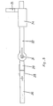
- the operating table shown in side view in FIG. 1 has a chassis which is designated in its entirety by 1 and is described in more detail below.
- a telescopically variable column is attached, the lower part with 2 and the upper part with 3.
- With the upper part 3 of the column is connected in its entirety with 4 designated storage area, which in turn carries a table top 5.
- the bearing surface 4 is not designed over the entire surface, but rather, for example, in the form of a frame, and the table top 5 consists of a radiation-permeable material, for example of wood.
- the column 2, 3 can be extended or shortened in order to raise or lower the bearing surface 4 and the table top 5 in the direction of their vertical longitudinal axis, designated z in FIG.
- crankcase 7 there is a transmission gear connected to the propeller shaft 6, so that the hand crank can either be plugged directly onto the propeller shaft 6 or onto the drive axis of the gearbox, so that the table can be raised or lowered at a lower or higher speed.
- a joint is arranged between the upper part 3 of the column and the bearing surface 4, the axis x of which runs horizontally and parallel to the table top 5.
- the table is tilted about its longitudinal axis.
- the tilting movement is possible on both sides, but only by limited angular amounts.
- the drive shaft is accessible from both narrow sides of the table, so that the hand crank used to drive it can be attached to one or the other side of the table.
- the gear which is expediently designed as a worm gear, is either self-locking or provided with a lock to prevent unintentional tipping movements.
- a swivel joint by means of which the table top 5 can be rotated about an axis running perpendicular to it, which is designated z in FIG. 1.
- the rotary movement can take place in both directions, but only by limited angular amounts.
- the drive of the swivel joint is designed in a similar manner to that of the tilt joint.
- the chassis designated in its entirety by 1 has two bars 8 running parallel to one another and two bars 9 running at an angle to one another.
- the spars 9, which point to the foot end of the table fixed rollers 10 are arranged, while there are 8 steering rollers 11 on the spars pointing to the head end of the table.
- FIG. 2 there are 4 device carrier rails 12, 13 and 14 on the bearing surface, which are used for fastening supports and other devices, depending on how and where they are used.
- a side support 15 is inserted into a device support rail 12, which supports the patient when the table is inclined about its longitudinal axis x.
- FIG. 2 denotes an extendable arm section, which can be better seen in FIG. 3, a view of the bearing surface 4 while leaving the table top 5.
- the arm section 16 is fastened to a rectangular frame consisting of rods 17 and cross members 18, specifically as required on one or the other of the crossbeams 18.
- the arm section 16 can be pivoted about the longitudinal axis of the crossbeam 18 and can be locked in any angular position by toggle locks 19.
- the rods 17 can be moved together in the longitudinal direction by a drive (not shown in the drawing) located in the substructure 4.
- the drive has a self-locking transmission, the drive shaft of which ends in the crankcase 7.
- a receiving opening 20 for the step holder 21 shown in FIGS. 6 and 7 is arranged in the bearing surface 4 and penetrates the table top 5.
- the receiving opening 2o has a square cross section, which corresponds to the square step holder foot 22.
- a step holder head 24 is connected to the step holder foot 22 via a plate 23 and in such a way that it is arranged eccentrically to the step holder foot 22.
- FIGS. 1 to 3 there is a receiving channel 25 which runs horizontally and in the longitudinal direction of the table in the bearing surface 4 below the table top 5.
- the receiving channel 25 has a square cross section and serves to receive a central extension 26, a beam-shaped body also with a square cross section.
- the central extension 26 is longitudinally displaceable in the receiving channel 25 and can be locked in it in the desired position by a knob 27.
- the central extension 26 is part of a spar arrangement.
- This spar arrangement which is generally used to hold the patient's legs, is shown in a top view in FIG. 4 and in a side view in FIG.
- two joints 28 are arranged symmetrically to the longitudinal axis of the central extension.
- the joints 28 have vertical axes and are used to connect two intermediate spars 29 to the central extension 26.
- the intermediate bars 29 can be pivoted independently of one another in a horizontal plane against the longitudinal axis of the central extension 26 by means of the joints 28 and can be locked in any position by toggle locks 30.
- End bars 32 are connected to the intermediate bars 29 via joints 31.
- the axes of the joints 31 run horizontally, so that the end bars 33 can be pivoted up and down in vertical planes against the intermediate bars 29, whereby they can be locked in the respectively desired position by toggle fasteners 33.
- Extension slides 34 can be moved on the end bars 32.
- the Endholme 32 are formed as toothed racks and in the extension slide 34 are arranged pinions which are operated by hand to the extension slide 34 ndholmen on the E to move to the desired position 32nd
- the Z rubbed senses the extension slide 34 are provided with ent.sperrbaren backstops to prevent inadvertent movement of the carriage on the extension Endholmen that would otherwise be possible because of the heavy weight of the extension carriage.
- the extension slides 34 are provided with locking devices which serve to fix the positions of the extension slides 34 on the end rails 32 as desired.
- extension slides 34 can be used on each of the end rails 32, so that their displaced support supports 35 can be arranged either between the end rails or outside the end rails.
- the Entsperrley the pinions or backstops in the extension slide 34 makes it possible to use these slides ndholmen first by hand into the desired position on the I bring 32 and then the operable by means such as by hand wheels To move pinions in the way necessary to set up a break.
- the joints 28 and 31 make it possible to bring the intermediate bars 29 and in particular the end bars 32 into a space-saving stowage position when the table is not in use, if the entire bar arrangement is not removed from the table when stowing, by pulling the central extension 26 out of the receiving channel 25 .
- To adjust the spar arrangement to the patient's body mass only the suitable positioning of the central extension 26 in the receiving channel 25 is required, not manipulations on two spars.
Landscapes
- Health & Medical Sciences (AREA)
- Orthopedic Medicine & Surgery (AREA)
- Engineering & Computer Science (AREA)
- Biomedical Technology (AREA)
- Life Sciences & Earth Sciences (AREA)
- Animal Behavior & Ethology (AREA)
- General Health & Medical Sciences (AREA)
- Public Health (AREA)
- Veterinary Medicine (AREA)
- Accommodation For Nursing Or Treatment Tables (AREA)
- Passenger Equipment (AREA)
- Spinning Or Twisting Of Yarns (AREA)
- Treatments For Attaching Organic Compounds To Fibrous Goods (AREA)
- Disintegrating Or Milling (AREA)
- Ladders (AREA)
Priority Applications (1)
| Application Number | Priority Date | Filing Date | Title |
|---|---|---|---|
| AT87111251T ATE60898T1 (de) | 1986-08-05 | 1987-08-04 | Operationstisch, insbesondere zur versorgung unfallverletzter. |
Applications Claiming Priority (2)
| Application Number | Priority Date | Filing Date | Title |
|---|---|---|---|
| EP86110806 | 1986-08-05 | ||
| EP86110806 | 1986-08-05 |
Publications (3)
| Publication Number | Publication Date |
|---|---|
| EP0255938A2 true EP0255938A2 (fr) | 1988-02-17 |
| EP0255938A3 EP0255938A3 (en) | 1988-09-07 |
| EP0255938B1 EP0255938B1 (fr) | 1991-02-20 |
Family
ID=8195318
Family Applications (1)
| Application Number | Title | Priority Date | Filing Date |
|---|---|---|---|
| EP87111251A Expired - Lifetime EP0255938B1 (fr) | 1986-08-05 | 1987-08-04 | Table d'opération, particulièrement pour le soin des accidentés |
Country Status (3)
| Country | Link |
|---|---|
| EP (1) | EP0255938B1 (fr) |
| AT (1) | ATE60898T1 (fr) |
| DE (1) | DE3768059D1 (fr) |
Cited By (3)
| Publication number | Priority date | Publication date | Assignee | Title |
|---|---|---|---|---|
| DE102017124315A1 (de) | 2017-10-18 | 2019-04-18 | Condor Gmbh Medicaltechnik | Seitenstütze an einem OP- oder Röntgentisch |
| US12453670B2 (en) | 2022-03-25 | 2025-10-28 | Mazor Robotics Ltd. | Surgical platform and trolley assembly |
| US12539244B2 (en) | 2023-05-26 | 2026-02-03 | Warsaw Orthopedic, Inc. | Surgical gantry and interface moveably interconnecting surgical table and gantry |
Family Cites Families (7)
| Publication number | Priority date | Publication date | Assignee | Title |
|---|---|---|---|---|
| DE66409C (de) * | E. MÜLLER in München | Glieder-Streckapparat | ||
| DE297104C (fr) * | ||||
| GB481836A (en) * | 1937-05-14 | 1938-03-18 | Adam Gruca | Improved operating table particularly for use in orthopaedic surgery |
| US2258782A (en) * | 1939-12-19 | 1941-10-14 | Rogers W Mckean | Physician's examining table |
| DE1054663B (de) * | 1955-12-10 | 1959-04-09 | Schuster & Schmidt Masch | Operationstisch |
| GB1312050A (en) * | 1970-02-24 | 1973-04-04 | Hugus Mek Verkstad Ab | Arrangement in operation tables for big animals |
| DE8621065U1 (de) * | 1986-08-06 | 1986-11-13 | Krips, Franz Josef, Dr. med., 4048 Grevenbroich | Operationstisch, insbesondere zur Versorgung Unfallverletzter |
-
1987
- 1987-08-04 DE DE8787111251T patent/DE3768059D1/de not_active Expired - Lifetime
- 1987-08-04 EP EP87111251A patent/EP0255938B1/fr not_active Expired - Lifetime
- 1987-08-04 AT AT87111251T patent/ATE60898T1/de not_active IP Right Cessation
Cited By (3)
| Publication number | Priority date | Publication date | Assignee | Title |
|---|---|---|---|---|
| DE102017124315A1 (de) | 2017-10-18 | 2019-04-18 | Condor Gmbh Medicaltechnik | Seitenstütze an einem OP- oder Röntgentisch |
| US12453670B2 (en) | 2022-03-25 | 2025-10-28 | Mazor Robotics Ltd. | Surgical platform and trolley assembly |
| US12539244B2 (en) | 2023-05-26 | 2026-02-03 | Warsaw Orthopedic, Inc. | Surgical gantry and interface moveably interconnecting surgical table and gantry |
Also Published As
| Publication number | Publication date |
|---|---|
| DE3768059D1 (de) | 1991-03-28 |
| EP0255938B1 (fr) | 1991-02-20 |
| ATE60898T1 (de) | 1991-03-15 |
| EP0255938A3 (en) | 1988-09-07 |
Similar Documents
| Publication | Publication Date | Title |
|---|---|---|
| DE68904115T2 (de) | Autonomer modul fuer die intensivpflege und reanimation. | |
| DE69725987T2 (de) | Medizinisches gerät mit patiententisch und hebevorrichtung in kompakter und steifer bauart | |
| CH457713A (de) | Operationstisch mit ortsfestem Unterteil, mit abhebbarer Liegefläche und Liegeflächentransportwagen | |
| EP0094620A2 (fr) | Table d'opération | |
| DE1930789B2 (de) | Krankenbett | |
| EP0273276A1 (fr) | Appareil de radiodiagnostic | |
| DE2459444A1 (de) | Montagewagen zur anordnung von teilstuecken eines modularen wandsystems | |
| EP0861952B1 (fr) | Echafaudage avec bras stabilisateur relevable | |
| EP0255938B1 (fr) | Table d'opération, particulièrement pour le soin des accidentés | |
| DE4319684C2 (de) | Entbindungsbett | |
| EP0617945A2 (fr) | Lit, en particulier lit de malades et/ou de soins | |
| DE69402978T2 (de) | Bett für intensivtherapie | |
| DE3515808C2 (fr) | ||
| DE8621065U1 (de) | Operationstisch, insbesondere zur Versorgung Unfallverletzter | |
| DE1541166A1 (de) | Patiententisch fuer die Untersuchung mit Roentgenstrahlen | |
| DE3500212A1 (de) | Patientenrolley | |
| DE4037015C2 (fr) | ||
| DE3241029C2 (fr) | ||
| DE1275725B (de) | Operationstisch | |
| DE3015644A1 (de) | Kombinationsmoebel fuer aerztliche behandlungsraeume | |
| DE102021100312A1 (de) | Vorrichtung zum Ausrichten einer Plattform sowie System und Patientenablage | |
| DE2946987A1 (de) | Einrichtung zum lagern eines patienten und verfahren zur aenderung der lage eines patienten unter verwendung der einrichtung | |
| EP1952860B1 (fr) | Table de baby-foot avec un piétement mobile | |
| DE3218356C2 (fr) | ||
| DE2618883A1 (de) | Stapelbares bett, insbesondere krankenhausbett, sowie verfahren zum stapeln derartiger betten |
Legal Events
| Date | Code | Title | Description |
|---|---|---|---|
| PUAI | Public reference made under article 153(3) epc to a published international application that has entered the european phase |
Free format text: ORIGINAL CODE: 0009012 |
|
| AK | Designated contracting states |
Kind code of ref document: A2 Designated state(s): AT BE CH DE ES FR GB GR IT LI LU NL SE |
|
| PUAL | Search report despatched |
Free format text: ORIGINAL CODE: 0009013 |
|
| AK | Designated contracting states |
Kind code of ref document: A3 Designated state(s): AT BE CH DE ES FR GB GR IT LI LU NL SE |
|
| 17P | Request for examination filed |
Effective date: 19890306 |
|
| 17Q | First examination report despatched |
Effective date: 19890518 |
|
| GRAA | (expected) grant |
Free format text: ORIGINAL CODE: 0009210 |
|
| AK | Designated contracting states |
Kind code of ref document: B1 Designated state(s): AT BE CH DE ES FR GB GR IT LI LU NL SE |
|
| PG25 | Lapsed in a contracting state [announced via postgrant information from national office to epo] |
Ref country code: SE Effective date: 19910220 Ref country code: NL Effective date: 19910220 Ref country code: GR Free format text: LAPSE BECAUSE OF FAILURE TO SUBMIT A TRANSLATION OF THE DESCRIPTION OR TO PAY THE FEE WITHIN THE PRESCRIBED TIME-LIMIT Effective date: 19910220 Ref country code: BE Effective date: 19910220 |
|
| REF | Corresponds to: |
Ref document number: 60898 Country of ref document: AT Date of ref document: 19910315 Kind code of ref document: T |
|
| REF | Corresponds to: |
Ref document number: 3768059 Country of ref document: DE Date of ref document: 19910328 |
|
| ITF | It: translation for a ep patent filed | ||
| ET | Fr: translation filed | ||
| PG25 | Lapsed in a contracting state [announced via postgrant information from national office to epo] |
Ref country code: ES Free format text: LAPSE BECAUSE OF FAILURE TO SUBMIT A TRANSLATION OF THE DESCRIPTION OR TO PAY THE FEE WITHIN THE PRESCRIBED TIME-LIMIT Effective date: 19910531 |
|
| GBT | Gb: translation of ep patent filed (gb section 77(6)(a)/1977) | ||
| NLV1 | Nl: lapsed or annulled due to failure to fulfill the requirements of art. 29p and 29m of the patents act | ||
| PG25 | Lapsed in a contracting state [announced via postgrant information from national office to epo] |
Ref country code: AT Effective date: 19910804 |
|
| PG25 | Lapsed in a contracting state [announced via postgrant information from national office to epo] |
Ref country code: LU Free format text: LAPSE BECAUSE OF NON-PAYMENT OF DUE FEES Effective date: 19910831 |
|
| PLBE | No opposition filed within time limit |
Free format text: ORIGINAL CODE: 0009261 |
|
| STAA | Information on the status of an ep patent application or granted ep patent |
Free format text: STATUS: NO OPPOSITION FILED WITHIN TIME LIMIT |
|
| 26N | No opposition filed | ||
| PGFP | Annual fee paid to national office [announced via postgrant information from national office to epo] |
Ref country code: GB Payment date: 19970801 Year of fee payment: 11 |
|
| PGFP | Annual fee paid to national office [announced via postgrant information from national office to epo] |
Ref country code: CH Payment date: 19970827 Year of fee payment: 11 |
|
| PG25 | Lapsed in a contracting state [announced via postgrant information from national office to epo] |
Ref country code: GB Free format text: LAPSE BECAUSE OF NON-PAYMENT OF DUE FEES Effective date: 19980804 |
|
| PG25 | Lapsed in a contracting state [announced via postgrant information from national office to epo] |
Ref country code: LI Free format text: LAPSE BECAUSE OF NON-PAYMENT OF DUE FEES Effective date: 19980831 Ref country code: CH Free format text: LAPSE BECAUSE OF NON-PAYMENT OF DUE FEES Effective date: 19980831 |
|
| GBPC | Gb: european patent ceased through non-payment of renewal fee |
Effective date: 19980804 |
|
| REG | Reference to a national code |
Ref country code: CH Ref legal event code: PL |
|
| PGFP | Annual fee paid to national office [announced via postgrant information from national office to epo] |
Ref country code: DE Payment date: 19991028 Year of fee payment: 13 |
|
| PGFP | Annual fee paid to national office [announced via postgrant information from national office to epo] |
Ref country code: FR Payment date: 20000131 Year of fee payment: 13 |
|
| PG25 | Lapsed in a contracting state [announced via postgrant information from national office to epo] |
Ref country code: FR Free format text: LAPSE BECAUSE OF NON-PAYMENT OF DUE FEES Effective date: 20010430 |
|
| PG25 | Lapsed in a contracting state [announced via postgrant information from national office to epo] |
Ref country code: DE Free format text: LAPSE BECAUSE OF NON-PAYMENT OF DUE FEES Effective date: 20010501 |
|
| REG | Reference to a national code |
Ref country code: FR Ref legal event code: ST |
|
| PG25 | Lapsed in a contracting state [announced via postgrant information from national office to epo] |
Ref country code: IT Free format text: LAPSE BECAUSE OF NON-PAYMENT OF DUE FEES;WARNING: LAPSES OF ITALIAN PATENTS WITH EFFECTIVE DATE BEFORE 2007 MAY HAVE OCCURRED AT ANY TIME BEFORE 2007. THE CORRECT EFFECTIVE DATE MAY BE DIFFERENT FROM THE ONE RECORDED. Effective date: 20050804 |