EP0255974A2 - Dispositif de photocoagulation de tissu morbide - Google Patents
Dispositif de photocoagulation de tissu morbide Download PDFInfo
- Publication number
- EP0255974A2 EP0255974A2 EP87201433A EP87201433A EP0255974A2 EP 0255974 A2 EP0255974 A2 EP 0255974A2 EP 87201433 A EP87201433 A EP 87201433A EP 87201433 A EP87201433 A EP 87201433A EP 0255974 A2 EP0255974 A2 EP 0255974A2
- Authority
- EP
- European Patent Office
- Prior art keywords
- optical fiber
- barrel
- light
- end portion
- coagulation
- Prior art date
- Legal status (The legal status is an assumption and is not a legal conclusion. Google has not performed a legal analysis and makes no representation as to the accuracy of the status listed.)
- Granted
Links
Images

Classifications
-
- G—PHYSICS
- G02—OPTICS
- G02B—OPTICAL ELEMENTS, SYSTEMS OR APPARATUS
- G02B6/00—Light guides; Structural details of arrangements comprising light guides and other optical elements, e.g. couplings
- G02B6/24—Coupling light guides
- G02B6/42—Coupling light guides with opto-electronic elements
- G02B6/4296—Coupling light guides with opto-electronic elements coupling with sources of high radiant energy, e.g. high power lasers, high temperature light sources
-
- A—HUMAN NECESSITIES
- A61—MEDICAL OR VETERINARY SCIENCE; HYGIENE
- A61B—DIAGNOSIS; SURGERY; IDENTIFICATION
- A61B18/00—Surgical instruments, devices or methods for transferring non-mechanical forms of energy to or from the body
- A61B18/18—Surgical instruments, devices or methods for transferring non-mechanical forms of energy to or from the body by applying electromagnetic radiation, e.g. microwaves
- A61B18/20—Surgical instruments, devices or methods for transferring non-mechanical forms of energy to or from the body by applying electromagnetic radiation, e.g. microwaves using laser
- A61B18/22—Surgical instruments, devices or methods for transferring non-mechanical forms of energy to or from the body by applying electromagnetic radiation, e.g. microwaves using laser the beam being directed along or through a flexible conduit, e.g. an optical fibre; Couplings or hand-pieces therefor
- A61B18/24—Surgical instruments, devices or methods for transferring non-mechanical forms of energy to or from the body by applying electromagnetic radiation, e.g. microwaves using laser the beam being directed along or through a flexible conduit, e.g. an optical fibre; Couplings or hand-pieces therefor with a catheter
-
- B—PERFORMING OPERATIONS; TRANSPORTING
- B23—MACHINE TOOLS; METAL-WORKING NOT OTHERWISE PROVIDED FOR
- B23K—SOLDERING OR UNSOLDERING; WELDING; CLADDING OR PLATING BY SOLDERING OR WELDING; CUTTING BY APPLYING HEAT LOCALLY, e.g. FLAME CUTTING; WORKING BY LASER BEAM
- B23K26/00—Working by laser beam, e.g. welding, cutting or boring
- B23K26/02—Positioning or observing the workpiece, e.g. with respect to the point of impact; Aligning, aiming or focusing the laser beam
- B23K26/06—Shaping the laser beam, e.g. by masks or multi-focusing
- B23K26/064—Shaping the laser beam, e.g. by masks or multi-focusing by means of optical elements, e.g. lenses, mirrors or prisms
- B23K26/0643—Shaping the laser beam, e.g. by masks or multi-focusing by means of optical elements, e.g. lenses, mirrors or prisms comprising mirrors
-
- B—PERFORMING OPERATIONS; TRANSPORTING
- B23—MACHINE TOOLS; METAL-WORKING NOT OTHERWISE PROVIDED FOR
- B23K—SOLDERING OR UNSOLDERING; WELDING; CLADDING OR PLATING BY SOLDERING OR WELDING; CUTTING BY APPLYING HEAT LOCALLY, e.g. FLAME CUTTING; WORKING BY LASER BEAM
- B23K26/00—Working by laser beam, e.g. welding, cutting or boring
- B23K26/70—Auxiliary operations or equipment
- B23K26/702—Auxiliary equipment
- B23K26/703—Cooling arrangements
-
- A—HUMAN NECESSITIES
- A61—MEDICAL OR VETERINARY SCIENCE; HYGIENE
- A61B—DIAGNOSIS; SURGERY; IDENTIFICATION
- A61B18/00—Surgical instruments, devices or methods for transferring non-mechanical forms of energy to or from the body
- A61B2018/00005—Cooling or heating of the probe or tissue immediately surrounding the probe
- A61B2018/00011—Cooling or heating of the probe or tissue immediately surrounding the probe with fluids
Definitions
- This invention relates to an apparatus for light coagulation of the morbid part such as cancer occurring on the wall of the stomach. More particularly, it relates to an apparatus for light coagulation by using laser light.
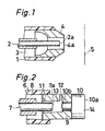
- FIG. 1 A typical prior art is shown in Fig. 1.
- An optical fiber 2 is inserted through a barrel 1 composed of, e.g., polyethylene and the space 3 between them is supplied with carbonic acid gas for washing and cooling the end face 2a of the optical fiber 2.
- the end portion of the barrel 1 has a protective member 4 composed of metal.
- the end face 2a of the optical fiber 2 is located inner to the end face 4a of the protective member 4, e.g., less than about 1 mm, in the axial alignment (left side of Fig. 1) and as the result the end face 2a of the optical fiber 2 is protected from damage when the barrel 1 and the optical fiber 2 are pushed into and moved in the axial direction. Laser light is led through the optical fiber 2.
- Light coagulation of a morbid part is carried out by illuminating laser light in the condition that the space between the surface of the morbid part 5 and the end face 2a of the optical fiber 2 positioned at the end portion of the barrel 1 is made to be, for example, about 1-2 cm so that the end portion of the optical fiber 2 is prevented from damaging when tissues adhere around the end face 2a of the core composed of quaritz glass and become to an abnormal high temperature.
- the space between the surface of the morbid part 5 and the end face 2a of the optical fiber 2 is varied by breathing of a man or the peristalisis of the stomach when the morbid part 5 is the wall of the stomach in the prior art shown in Fig. 1. Therefore, it is difficult to carry out the light coagulation of the tissues of the morbid part 5 in the desired condition. Additionally, when the tissues, blood and others adhere to the end face 2a of the optical fiber 2, they are heated to be at a high temperature and damage the end portion of the optical fiber 2.
- the carbonic acid gas supplied to the space 3 for washing and cooling is comparatively large quantity of flow, e.g., 400cc/minute or more. Therefore, the stomach of the patient is swollen in a comparatively short time when the barrel 1 was inserted into the stomach, which gives pains to the patient and there is the possibility that the tissue, e.g. wall of a digestive tract will be bored erroneously with the pressure of the gas.
- FIG. 2 An optical fiber 7 is inserted through the barrel 6 and the space 8 is fed with cooling water by a compressor.
- the end portion of the barrel 6 has a connecting member 9 composed of metal and a contact member 10 composed of new ceramic, e.g., artificial sapphire connected to the connecting member 9.
- the end face 10a of the contact member 10 is an plane being vertical to the axis extending to right and left in Fig. 2.
- a passage 11 is formed between the connecting member 9 and the optical fiber 7.
- water passed through the passage 11 and fed from the space 8 passes through the space 13 between the end face 7a of the core layer of the optical fiber 7 and the end face 10b of the contact member 10 facing to the optical fiber 7 of the contact member 10, and is supplied to wash and cool the end face 7a of the core layer of the optical fiber 7 and the end face 10b of the contact member 10 facing to the optical fiber 7, and a jet of water is sent out from the nozzle 12 to wash and cool the contact member 10.
- a jet of water is sent out from the nozzle 12 to wash and cool the contact member 10.
- the light coagulation is carried out by contacting the end face 10a of the contact member 10 to the tissue to be coagulated optically so that the morbid part can be coagulated optically in the desired state even if the morbid part of the tissue to be coagulated optically is the wall of the stomach and it stirs with vermiculation and the like and furthermore the morbid coagulation may be carried out by illumination of laser light from the tangential direction.
- This invention has a benefit that the laser light supplied to the optical fiber 7 may have lower output, e.g., about 10 - 20 W compared with the prior art noted in Fig. 1, since the light coagulation is carried out by contacting the contact member 10 composed of new ceramic such as artificial sapphire having a high melting point to the morbid part.
- the prior art shown in Fig. 2 has a new problem. Namely, the laser light refracts and concentrates into the position around the center shown by the reference symbol 14 at the end face 10a of the contact member 10 and the position and its around are heated to higher temperature compared with the part around the heated part and a uniform distribution of the laser light cannot be obtained over the whole of the end face 10a. Accordingly, uniform light coagulation of the tissue cannot be resulted in the morbid part contacting to the end face 10a of the contact member 10.
- the other problem of the prior art shown in Fig. 2 is that the position 14 around the center of the contact member 10 may become depressed and easily damaged since the laser light concentrates to the position and heats it to a high temperature. Accordingly, it is difficult to conjecture the coagulating state of the morbid part during the treatment with the laser light illumination. Additionally, the life of the contact member 10 is short.
- the light coagulation with laser light of a high output cannot be carried out since heat is generated locally at the position 14 around the center of the contact member 10.
- the contact member 10 is composed of new ceramic such as artificial sapphire as noted above and therefore it is expensive.
- the purpose of this invention is to provide an improved apparatus for light coagulation of the morbid part which makes the distribution of luminous intensity of laser light illuminating the morbid part uniform and makes the life of an optical fiber longer, makes the laser light of a large output applicable and further makes the treatment carried out at a low cost.
- an apparatus for light coagulation of the morbid part comprises an optical fiber, a laser source for generating laser light and for leading the light to the optical fiber, a flexible barrel which the optical fiber is inserted through and means for supplying transparent cooling water into the space between the outside of the optical fiber and the inside of the barrel, an end portion of the optical fiber being positioned inner to an end portion of the barrel in the axial alignment.
- the reflection ratio is improved in the inside of the end portion of the barrel.
- the end portion of the barrel is composed of metal and is exchangeable.
- the barrel is composed of synthetic resin in the whole length and the inside of the end portion is improved in reflection ratio by plating with metal.
- an apparatus for light coagulation of the morbid part comprises an optical fiber, a laser source for generating laser light and for leading the light to the optical fiber, a flexible barrel which the optical fiber is inserted through and means for supplying transparent cooling water into the space between the outside of the optical fiber and the inside of the barrel, an end portion of the barrel being made of metal and being exchangeable.
- the above end portion of the barrel is made of aluminum alloy.
- the transparent cooling water is in contact with the end face where the laser light of the optical fiber is illuminated. Therefore, the optical fiber is sufficiently cooled herewith, the distribution of the laser light is made uniform and the life of the optical fiber is lengthen. Additionally, the laser light of a high output can be used to illuminate the morbid part.
- the end portion of the optical fiber is positioned inner to the end portion of the barrel in the axial alignment so that the end portion of the barrel is made contact with the surface of the tissue to be coagulated with light and the light coagulation of the desired area can be carried out accurately. It is also possible to illuminate the laser light from the tangential direction to the morbid part to carry out the light coagulation.
- the end portion of the optical fiber is positioned inner in the axial alignment in the state that the end of the barrel is in contact with the morbid part and therefore, the end portion of the optical fiber is never in contact with the morbid part. Accordingly, the end portion of the optical fiber is prevented from adhesion of tissues, blood and the like. Generation of heat to an abnormal high temperature is also prevented. Therefore, the optical fiber is protected from damage.
- the cooling water is transparent and the laser light is naturally not intercepted.
- the distribution of luminous intensity of the laser light illuminated to the morbid part is uniform and a local generation of an area heated to a high temperature is prevented so that the life of the optical fiber is extended and a treatment can be carried out with laser light of a high output and also at a low cost.
- the end portion of the barrel is made of metal, for example, aluminum alloy and the inside has a specific luster depending on the metal.
- the reflection ratio is improved. Accordingly, the laser light from the optical fiber can be efficiently reflected and led to the morbid part.
- the end portion of the barrel is exchangeable. It will be exchanged by itself when the end part is damaged, worn away or stained. Thus, the maintenance is easy and other parts having a few possibility of damage may be used continuously for a long period.
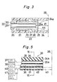
- Fig. 3 is a cross-sectional view of an example of this invention.
- An optical fiber 22 having flexibility is inserted into a barrel 21 composed of a flexible material, e.g., polyethylene.
- the end portion of the barrel 21 is composed with a connecting member 23 made of, e.g., stainless steel and a contact member 24.
- the contact member 24 is composed of aluminum alloy with high hardness but is endurable to fine threading work and the like.
- the contact member 24 may be composed of other metals such as stainless steel and the like.
- the contact member 24 is a right cylinder of which inside is produced to have glaze so as to reflect laser light with a high efficiency and is, e.g., 1.4 mm ⁇ -2 mm ⁇ .
- the wall thickness is, e.g. 0.2 - 0.4 mm.
- a female thread is cut on the inner periphery surface of the starting portion of the contact member 24.
- the connecting member 23 has a connecting portion 26 which may be inserted into the barrel 21 composed of polyethylene and the like, a flange portion 27 and a threading portion 28 having a male thread.
- the male thread 25 of the contact member 24 is freely screwed in and out with the threading portion 28.
- the connecting portion 26 is cut to taper so as to retain the portions of the truncated cones having the largest diameter towards the flange portion 27 in axial alignment so that it is inserted into the barrel 21 easily and prevented from slipping out.
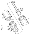
- Fig. 4 shows a disassemble perspective side view of the connecting member 23 and the surroundings.
- the optical fiber 22 is provided with a core layer 29 and a clad layer 30 surrounding the core layer 29.
- the clad layer 30 is removed near at the end portion of the optical fiber 22 and the resultant bare core layer 29 is inserted into a through hole 31 of the connecting member 23.
- the end face 29a of the core layer 29 is at the inner position sunken from the end face 24a of the contact member 24 (the left side in Fig. 3) at the distance of l1 in axial alignment.
- the distance of l1 is, e.g., about 5 mm.
- Fig. 5 is a cross-sectional view of an endoscope 33 carried out in relation to the present invention.
- Fig. 6 is a cross-sectional view from the line VI-VI.
- the body 34 of the endoscope 33 there are equipped with an optical fiber for lighting 35 and an optical fiber for image transmission 36.
- a light source 37 is connected to the optical fiber for lighting 35 and the light from the light source 37 reaches to the morbid part 38 to be coagulated with light and the surroundings through the optical fiber for lighting 35 and the end face 35a.
- the image of the lighted portion of the morbid part 38 is transmitted to display means 39 through the optical fiber for image transmission 36.
- the display means 39 may be composed of the one for direct ocular observation having an eyepiece or may be composed of the one displaying with means such as a cathode ray tube.
- Laser light is led from a laser source 40 to the optical fiber 22 deposited in the barrel 21 of the apparatus for light coagulation of this invention.
- the laser source 40 is, e.g., Nd-YAG laser and the output is, e.g. 20 - 30 W.
- the barrel 21 is also connected with a source of cooling water supply 41. From the source of cooling water supply 41, cooling water is made pass through the space 20 between the outside of the optical fiber 22 and the inside of the barrel 21 by pressure.
- the flow rate is, e.g., 2cc/min.
- the barrel 21 can be displaced in the vertical direction in the inside of the through hole 42 extending to the vertical direction formed in the body 34 of the endoscope 33 and the barrel 21 will be projected as shown by the reference number 43 when the light coagulation is carried out so that the end face 24a of the contact member 24 is in contact with the position to be coagulated in the morbid part 38.
- the area to be treated with the light coagulation is illuminated by 35a of an optical fiber for lighting 35.
- the movement during the treatment can be observed at the outside by using the display means 39 with the optical fiber for image transmission 36.
- the body 34 of the endoscope 33 is composed of a flexible material, e.g., gum.
- the space 20 is supplied with cooling water and the optical fiber 22 in the state of leading the laser light will be in contact with the morbid part 38 at the end face 24a of the contact member 24 so as to carry out the light coagulation.
- the end face 29a of the core layer 29 of the optical fiber 22 is at the position far from the morbid part 38 in the distance of l1 when the end face 24a of the contact member 24 is in contact with the morbid part 38. Therefore, the morbid part 38 and blood will not adhere to the end face 29a and the end face 29a is prevented from being heated to an abnormally high temperature.
- the optical fiber 22 is always in contact with cooling water and therefore cooling of the optical fiber 22 is surely maintained.
- the end face 29a of the core layer 29 of the optical fiber 22 is a plane vertical to the axis of the optical fiber 22 so that it can make the laser light distribute the luminous intensity uniform. Therefore, the light coagultion state of the morbid part 38 by laser light is easily conjectured so that operation can be carried out smooth.
- the external form of the light illuminated from the end face 29a of the core layer 29 of the optical fiber 22 is shown with reference number 44 and the connecting member 23 is in the size not being an obstacle to illumination of the laser light.
- the inside of the contact member 24 has a good reflection ratio as noted above so that the morbid part 38 is effectively illuminated by the laser light.
- the laser light from the optical fiber 22 certainly illuminates the morbid part 38 because the cooling water is transparent.
- the light coagulation of 2.2 mm ⁇ and 1.6 mm in depth occurred at the morbid part 38 in the stomach wall when laser light was generated for 12 second from the laser light source 40 having an output of 20 w.
- Other transparent liquid may be used instead of cooling water.
- the cooling liquid such as cooling water do not present any problem to the treated patient such as pains by the cooling liquid since the amount of the cooling liquid is a little. Therefore, smooth operation is ensured within the limited treating period and the operation is carried out with safety.
- the contact member 24 is convenient from a sanitary point of view since it is screwed in the connecting member 23 and can be screwed out and changed.
- the contact member 24 may be exchanged to the new one when it gets damaged, worn away or stained so that the maintenance is easy and it is convenient for sanitary reasons. Additionally, it is possible to remove the connecting member 23 from the barrel 21 and exchange it.
- the outer faces of the contact member 24 and the flange part 27 of the connecting member 23 may be coated with Teflon (Trade Mark), by which they can be easily wiped out when tissues such as skin adhere to the outer faces. Thus, the contact member 24 and the connecting member 23 can be kept clean.
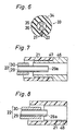
- Fig. 7 shows a cross-sectional view of other example of this invention.
- the example is similar to the above example and the corresponding parts have the same reference numbers.
- the contact member 46 is composed of the same material as the above contact member 24 and the reflection ratio of the inside is satisfactory.
- the starting portion 47 of the contact member 46 is fixed into the inside of the barrel 21 with free loading.
- the composition is more simplified in this example.
- Fig. 8 shows a cross-sectional view of other example.
- This example is similar to the above example and has the same reference numbers to the corresponding parts.
- the remarkable point is that a layer having a satisfactory reflexion ratio e.g. aluminum, is formed by plating at the inside of the end portion of the barrel 21. The light from the optical fiber 22 is reflected sufficiently by this layer to illuminate the morbid part.
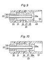
- Fig. 9 is a cross-sectional view of other example of this invention, which is similar to the examples shown in Figs. 3 and 4.
- the inside 50 of the contact member 49 is formed to be a hollow truncated cone, of which part having larger diameter is put towards the right of Fig. 7, namely the end side.
- Fig. 10 is furthermore a cross-sectional view of other example.
- a male screw is formed at the starting portion of the contact member 51 and the connecting member 23 has a female screw 28a so that the fixing is performed each other. Additionally, it is possible to remove the connecting member 23 from the barrel 21 and exchange it.
- Fig. 11 is a cross-sectional view of other example.
- the contact member 52 is formed to be trumpet shaped of which part having larger diameter is put toward the end side.
- the trumpet shaped contact member 52 may be removed from the connecting member and exchanged. It is possible to remove the connecting member 23 from the barrel 21 and exchange it.
Landscapes
- Physics & Mathematics (AREA)
- Optics & Photonics (AREA)
- Engineering & Computer Science (AREA)
- Plasma & Fusion (AREA)
- Mechanical Engineering (AREA)
- Health & Medical Sciences (AREA)
- Surgery (AREA)
- Life Sciences & Earth Sciences (AREA)
- General Physics & Mathematics (AREA)
- Molecular Biology (AREA)
- Nuclear Medicine, Radiotherapy & Molecular Imaging (AREA)
- Electromagnetism (AREA)
- Biomedical Technology (AREA)
- Heart & Thoracic Surgery (AREA)
- Medical Informatics (AREA)
- Otolaryngology (AREA)
- Animal Behavior & Ethology (AREA)
- General Health & Medical Sciences (AREA)
- Public Health (AREA)
- Veterinary Medicine (AREA)
- Radiation-Therapy Devices (AREA)
- Laser Surgery Devices (AREA)
Applications Claiming Priority (4)
| Application Number | Priority Date | Filing Date | Title |
|---|---|---|---|
| JP61176265A JPS6331678A (ja) | 1986-07-25 | 1986-07-25 | 病変部の光凝固装置 |
| JP176265/86 | 1986-07-25 | ||
| JP62051748A JPS6331651A (ja) | 1987-03-05 | 1987-03-05 | 内視鏡 |
| JP51748/87 | 1987-03-05 |
Publications (3)
| Publication Number | Publication Date |
|---|---|
| EP0255974A2 true EP0255974A2 (fr) | 1988-02-17 |
| EP0255974A3 EP0255974A3 (en) | 1988-12-14 |
| EP0255974B1 EP0255974B1 (fr) | 1993-06-16 |
Family
ID=26392313
Family Applications (1)
| Application Number | Title | Priority Date | Filing Date |
|---|---|---|---|
| EP87201433A Expired - Lifetime EP0255974B1 (fr) | 1986-07-25 | 1987-07-24 | Dispositif de photocoagulation de tissu morbide |
Country Status (2)
| Country | Link |
|---|---|
| EP (1) | EP0255974B1 (fr) |
| DE (1) | DE3786206T2 (fr) |
Cited By (7)
| Publication number | Priority date | Publication date | Assignee | Title |
|---|---|---|---|---|
| EP0402017A3 (fr) * | 1989-06-09 | 1991-03-06 | Premier Laser Systems, Inc. | Appareil à fibre optique pour utilisation avec laser médical |
| US5207673A (en) * | 1989-06-09 | 1993-05-04 | Premier Laser Systems, Inc. | Fiber optic apparatus for use with medical lasers |
| WO1993019680A1 (fr) * | 1992-04-06 | 1993-10-14 | Laser-Medizin-Zentrum Gmbh Berlin | Tige d'application de photo-thermotherapie |
| US5300067A (en) * | 1991-08-23 | 1994-04-05 | Hoya Corporation | Laser treatment device |
| US5352221A (en) * | 1992-11-04 | 1994-10-04 | Fumich Robert M | Guide tip apparatus for laser surgery |
| WO2003011160A3 (fr) * | 2001-07-30 | 2004-03-04 | Biotex Inc | Catheter laser a extremite distale refroidie servant a la detection et a l'ablation d'arythmies cardiaques |
| CN103006323A (zh) * | 2012-11-21 | 2013-04-03 | 首都医科大学 | 喷液部件、清洗枪及创面处理装置 |
Family Cites Families (5)
| Publication number | Priority date | Publication date | Assignee | Title |
|---|---|---|---|---|
| DE2106470A1 (de) * | 1971-02-11 | 1972-08-24 | Henker H | Flexibles endoskopisches Laserskalpell mit Beobachtungsoptik |
| US3821510A (en) * | 1973-02-22 | 1974-06-28 | H Muncheryan | Hand held laser instrumentation device |
| US4592353A (en) * | 1984-05-22 | 1986-06-03 | Surgical Laser Technologies Ohio, Inc. | Medical and surgical laser probe |
| AT380634B (de) * | 1985-01-14 | 1986-06-25 | Schmidt Kloiber Heinz | Einrichtung zur zerst!rung von harnwegkonkrementen |
| FR2597744A1 (fr) * | 1986-04-29 | 1987-10-30 | Boussignac Georges | Catheter cardio-vasculaire pour tir au rayon laser |
-
1987
- 1987-07-24 DE DE87201433T patent/DE3786206T2/de not_active Expired - Fee Related
- 1987-07-24 EP EP87201433A patent/EP0255974B1/fr not_active Expired - Lifetime
Cited By (10)
| Publication number | Priority date | Publication date | Assignee | Title |
|---|---|---|---|---|
| EP0402017A3 (fr) * | 1989-06-09 | 1991-03-06 | Premier Laser Systems, Inc. | Appareil à fibre optique pour utilisation avec laser médical |
| US5207673A (en) * | 1989-06-09 | 1993-05-04 | Premier Laser Systems, Inc. | Fiber optic apparatus for use with medical lasers |
| US5300067A (en) * | 1991-08-23 | 1994-04-05 | Hoya Corporation | Laser treatment device |
| WO1993019680A1 (fr) * | 1992-04-06 | 1993-10-14 | Laser-Medizin-Zentrum Gmbh Berlin | Tige d'application de photo-thermotherapie |
| US6039728A (en) * | 1992-04-06 | 2000-03-21 | Ceram Optec Gmbh | Working shaft for photo-thermal therapy |
| US5352221A (en) * | 1992-11-04 | 1994-10-04 | Fumich Robert M | Guide tip apparatus for laser surgery |
| US5662646A (en) * | 1992-11-04 | 1997-09-02 | Fumich; Robert Mark | Method and apparatus for laser surgery |
| WO2003011160A3 (fr) * | 2001-07-30 | 2004-03-04 | Biotex Inc | Catheter laser a extremite distale refroidie servant a la detection et a l'ablation d'arythmies cardiaques |
| CN103006323A (zh) * | 2012-11-21 | 2013-04-03 | 首都医科大学 | 喷液部件、清洗枪及创面处理装置 |
| CN103006323B (zh) * | 2012-11-21 | 2014-12-10 | 首都医科大学 | 喷液部件、清洗枪及创面处理装置 |
Also Published As
| Publication number | Publication date |
|---|---|
| DE3786206D1 (de) | 1993-07-22 |
| EP0255974B1 (fr) | 1993-06-16 |
| EP0255974A3 (en) | 1988-12-14 |
| DE3786206T2 (de) | 1993-10-21 |
Similar Documents
| Publication | Publication Date | Title |
|---|---|---|
| US4537193A (en) | Laser endocoagulator apparatus | |
| US5476461A (en) | Endoscopic light delivery system | |
| US5558669A (en) | Fiber optic sleeve for surgical instruments | |
| Verdaasdonk et al. | Laser light delivery systems for medical applications | |
| US5836941A (en) | Laser probe | |
| US5323766A (en) | Illuminating endo-photocoagulation probe | |
| US5611797A (en) | Combination handpiece and surgical laser tool | |
| KR960014023B1 (ko) | 레이저광의 조사장치 | |
| KR100206617B1 (ko) | 레이저 비디오 내시경 | |
| US6024738A (en) | Laser catheter apparatus for use in arteries or other narrow paths within living organisms | |
| US6129721A (en) | Medical laser treatment device and laser probe for the same | |
| US5300067A (en) | Laser treatment device | |
| US20070179485A1 (en) | Fiber optic laser energy delivery devices | |
| US5685824A (en) | Prostascope with a bridge | |
| CA2241137A1 (fr) | Manchon a fibres optiques pour instruments chirurgicaux | |
| EP0255974A2 (fr) | Dispositif de photocoagulation de tissu morbide | |
| WO2008092106A2 (fr) | Pointes de fibres optiques à sorties modifiées | |
| EP0634947A1 (fr) | Appareil et procede de chirurgie oculaire | |
| CA2324271A1 (fr) | Instrument d'eclairage destine notamment a etre utilise dans la microchirurgie ophtalmologique | |
| US5833684A (en) | Handpiece for a stomatological application for laser light | |
| US5549600A (en) | Surgical laser probe with thermal cutting | |
| US12251337B2 (en) | Eye treatment device, in particular for glaucoma | |
| JP3869535B2 (ja) | 内視鏡 | |
| JP4049859B2 (ja) | 内視鏡装置 | |
| US5579423A (en) | Optical fiber laser device |
Legal Events
| Date | Code | Title | Description |
|---|---|---|---|
| PUAI | Public reference made under article 153(3) epc to a published international application that has entered the european phase |
Free format text: ORIGINAL CODE: 0009012 |
|
| AK | Designated contracting states |
Kind code of ref document: A2 Designated state(s): CH DE FR GB LI |
|
| PUAL | Search report despatched |
Free format text: ORIGINAL CODE: 0009013 |
|
| AK | Designated contracting states |
Kind code of ref document: A3 Designated state(s): CH DE FR GB LI |
|
| 17P | Request for examination filed |
Effective date: 19890608 |
|
| 17Q | First examination report despatched |
Effective date: 19920227 |
|
| GRAA | (expected) grant |
Free format text: ORIGINAL CODE: 0009210 |
|
| AK | Designated contracting states |
Kind code of ref document: B1 Designated state(s): CH DE FR GB LI |
|
| PGFP | Annual fee paid to national office [announced via postgrant information from national office to epo] |
Ref country code: FR Payment date: 19930623 Year of fee payment: 7 |
|
| PGFP | Annual fee paid to national office [announced via postgrant information from national office to epo] |
Ref country code: GB Payment date: 19930713 Year of fee payment: 7 |
|
| REF | Corresponds to: |
Ref document number: 3786206 Country of ref document: DE Date of ref document: 19930722 |
|
| PGFP | Annual fee paid to national office [announced via postgrant information from national office to epo] |
Ref country code: CH Payment date: 19930723 Year of fee payment: 7 |
|
| PGFP | Annual fee paid to national office [announced via postgrant information from national office to epo] |
Ref country code: DE Payment date: 19930927 Year of fee payment: 7 |
|
| ET | Fr: translation filed | ||
| PLBE | No opposition filed within time limit |
Free format text: ORIGINAL CODE: 0009261 |
|
| STAA | Information on the status of an ep patent application or granted ep patent |
Free format text: STATUS: NO OPPOSITION FILED WITHIN TIME LIMIT |
|
| 26N | No opposition filed | ||
| PG25 | Lapsed in a contracting state [announced via postgrant information from national office to epo] |
Ref country code: GB Effective date: 19940724 |
|
| PG25 | Lapsed in a contracting state [announced via postgrant information from national office to epo] |
Ref country code: LI Effective date: 19940731 Ref country code: CH Effective date: 19940731 |
|
| GBPC | Gb: european patent ceased through non-payment of renewal fee |
Effective date: 19940724 |
|
| PG25 | Lapsed in a contracting state [announced via postgrant information from national office to epo] |
Ref country code: FR Effective date: 19950331 |
|
| REG | Reference to a national code |
Ref country code: CH Ref legal event code: PL |
|
| PG25 | Lapsed in a contracting state [announced via postgrant information from national office to epo] |
Ref country code: DE Effective date: 19950401 |
|
| REG | Reference to a national code |
Ref country code: FR Ref legal event code: ST |