EP0255992A2 - Doppelpoliger Schalter für elektrische Einrichtungen im zivilen Bereich, mit einer Lichtbogenkommutierungseinrichtung - Google Patents
Doppelpoliger Schalter für elektrische Einrichtungen im zivilen Bereich, mit einer Lichtbogenkommutierungseinrichtung Download PDFInfo
- Publication number
- EP0255992A2 EP0255992A2 EP87830216A EP87830216A EP0255992A2 EP 0255992 A2 EP0255992 A2 EP 0255992A2 EP 87830216 A EP87830216 A EP 87830216A EP 87830216 A EP87830216 A EP 87830216A EP 0255992 A2 EP0255992 A2 EP 0255992A2
- Authority
- EP
- European Patent Office
- Prior art keywords
- circuit breaker
- diaphragm
- pole
- moving
- socket
- Prior art date
- Legal status (The legal status is an assumption and is not a legal conclusion. Google has not performed a legal analysis and makes no representation as to the accuracy of the status listed.)
- Granted
Links
Images

Classifications
-
- H—ELECTRICITY
- H01—ELECTRIC ELEMENTS
- H01H—ELECTRIC SWITCHES; RELAYS; SELECTORS; EMERGENCY PROTECTIVE DEVICES
- H01H71/00—Details of the protective switches or relays covered by groups H01H73/00 - H01H83/00
- H01H71/002—Details of the protective switches or relays covered by groups H01H73/00 - H01H83/00 with provision for switching the neutral conductor
-
- H—ELECTRICITY
- H01—ELECTRIC ELEMENTS
- H01H—ELECTRIC SWITCHES; RELAYS; SELECTORS; EMERGENCY PROTECTIVE DEVICES
- H01H73/00—Protective overload circuit-breaking switches in which excess current opens the contacts by automatic release of mechanical energy stored by previous operation of a hand reset mechanism
- H01H73/02—Details
- H01H73/18—Means for extinguishing or suppressing arc
-
- H—ELECTRICITY
- H01—ELECTRIC ELEMENTS
- H01H—ELECTRIC SWITCHES; RELAYS; SELECTORS; EMERGENCY PROTECTIVE DEVICES
- H01H71/00—Details of the protective switches or relays covered by groups H01H73/00 - H01H83/00
- H01H71/02—Housings; Casings; Bases; Mountings
- H01H71/0207—Mounting or assembling the different parts of the circuit breaker
- H01H2071/0242—Assembling parts of a circuit breaker by using snap mounting techniques
-
- H—ELECTRICITY
- H01—ELECTRIC ELEMENTS
- H01H—ELECTRIC SWITCHES; RELAYS; SELECTORS; EMERGENCY PROTECTIVE DEVICES
- H01H71/00—Details of the protective switches or relays covered by groups H01H73/00 - H01H83/00
- H01H71/10—Operating or release mechanisms
- H01H71/12—Automatic release mechanisms with or without manual release
- H01H71/121—Protection of release mechanisms
-
- H—ELECTRICITY
- H01—ELECTRIC ELEMENTS
- H01H—ELECTRIC SWITCHES; RELAYS; SELECTORS; EMERGENCY PROTECTIVE DEVICES
- H01H79/00—Protective switches in which excess current causes the closing of contacts, e.g. for short-circuiting the apparatus to be protected
-
- H—ELECTRICITY
- H01—ELECTRIC ELEMENTS
- H01H—ELECTRIC SWITCHES; RELAYS; SELECTORS; EMERGENCY PROTECTIVE DEVICES
- H01H9/00—Details of switching devices, not covered by groups H01H1/00 - H01H7/00
- H01H9/30—Means for extinguishing or preventing arc between current-carrying parts
- H01H9/46—Means for extinguishing or preventing arc between current-carrying parts using arcing horns
- H01H9/465—Shunt circuit closed by transferring the arc onto an auxiliary electrode
Definitions
- This invention relates to a double-pole circuit breaker for enclosed boxes of civil range electric equipment, being of a type which comprises, within a body, a neutral pole and a protected pole, as well as a moving contact and a fixed contact for each pole.
- a circuit breaker as indicated is characterized in that it comprises a diaphragm in said body, two chambers formed in said body on opposed sides of the diaphragm, each adapted to accommodate a respective one of said moving contacts for movement therein along a preset path toward and away from a respective one of said fixed contacts, a throughgoing socket in said diaphragm, and a metal crosspiece having a middle portion inserted in said socket and end portions overhanging into said chambers at a preset distance from said path.
- the numeral 1 designates generally a circuit breaker according to the invention, which is adapted for mounting on a small carrier frame, not shown in the drawing, for enclosed boxes of civil range electric equipment. Understandably, such circuit breakers as this may also be used for jutting installations and in exchanges.
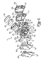
- the inventive circuit breaker 1 comprises a core member 2 of substantially parallelepipedal shape which is formed by a substantially rectangular central diaphragm 3 surrounded, along one side and the two sides adjoining said one side, by a framing member 4.
- the circuit breaker 1 further comprises a pair of cheek pieces, namely a first cheek piece 5 and second cheek piece 6, as well as fasteners 7 for securing the cheek pieces 5 and 6 on the core member 2, to form a box-type body 8 adapted for mounting on a carrier frame from the MAGIC civil range which constitutes a module measuring preferably 23-25 mm thereacross.
- the cheek pieces 5 and 6 are provided with attachment means indicated at 5a and 6a, respectively, in the form of blocks of a preset size adapted to engage with mating means of attachment associated with the carrier frame from the MAGIC range.
- the fasteners 7 for securing the cheek pieces 5 and 6 on the core member 2 comprise four screws 9 extending from the cheek piece 5 through the core member 2 and in thread engagement with the cheek piece 6.
- the circuit breaker 1 also comprises a further pair of cheek pieces 10 and 11, respectively interchangeable with the cheek pieces 5 and 6 in the first-mentioned pair and attachable to the core member 2 by means of like fasteners 7.
- the circuit breaker 1 would fit in a carrier frame from the LIVING civil range.
- the cheek pieces 10 and 11 are provided with respective attachment means 10a and 11a in the form of blocks of a preset size adapted for engagement with mating means of attachment associated with the carrier frame from the LIVING range.
- the circuit breaker 1 also comprises a further pair of cheek pieces 12 and 13, also respectively interchangeable with the cheek pieces 5 and 6 in the first-mentioned pair and attachable to the core member 2 by means of like fasteners 7.
- the circuit breaker 1 is adapted to fit in a carrier frame from the TEKNE range.
- the cheek pieces 12 and 13 are provided with hook-on dogs 12a and 13a adapted to engage in corresponding sockets associated with the carrier frame from the TEKNE range.
- a pole pair In the body 8 of the circuit breaker 1 there are housed a pole pair, namely a protected pole 14 and neutral pole 15.
- the protected pole 14 is accommodated between the core member 2 and the cheek piece 5, and extends between an input terminal 16 and an output terminal 17.
- a fixed contact 18 located on the input terminal 16 side
- a moving contact 19 located on the output terminal 17 side.
- the neutral pole 15 is accommodated between the core member 2 and the cheek piece 6, and extends between an input terminal 20 and an output terminal 21.
- the circuit breaker 1 further comprises circuit breaking linkages, comprehensively designated 24, which are supported on the core member 2.
- the linkages 24 include a key 25 and a moving contact holder assembly 26. Between the key 25 and the moving contact holder assembly 26 there is provided a toggle mechanism, known per se and indicated at 27.
- the circuit breaking linkages 24 also comprise a spring-loaded lever 28 for hooking the moving contact holder assembly 26 in the make position of the circuit breaker.
- the lever 28 is pivoted to the diaphragm 3 astride it and has two lugs 29 and 30 located on opposed sides of the diaphragm 3, the lug 29 being located on the cheek piece 5 side and the lug 30 being located on the cheek piece 6 side.
- the moving contact holder assembly 26 comprises a contact carrier body 31 being a unitary construction from a non-conductive material, such as a plastics material, and straddling the diaphragm 3 of the core member 2.
- Spring mounted to the contact carrier body 31 are the two moving contacts 19 and 23 through respective means of attchment 32, to be explained hereinafter.
- the two moving contacts 19 and 23 extend on opposed sides of the diaphragm 3 into two respective arcing chambers 33 and 34 formed in the body 8 between the core member 2 and the cheek pieces 5 and 6, respectively.
- the arcing chambers 33 and 34 are formed with respective venting slits 33a and 34a which open outwards and are formed in part in the cheek pieces and in part in the framing member 4 of the core member 2, on opposed sides with respect to the central diaphragm 3.
- the moving contacts 19 and 23 are movable through equal paths T toward and away from their respective fixed contacts 19 and 22 facing said chambers 33 and 34, respectively.
- a throughgoing socket 35 having an L-shaped cross-section.
- a metal crosspiece made preferably of copper-plated iron, which has an L-shaped cross-section mating with the L-shaped cross-section of the throughgoing socket 35.
- the crosspiece penetrates, with a middle portion 37 thereof, the throughgoing socket 35, in a substantially force fit relationship, and has opposed end portions 38 and 39 overhanging into said chambers 33 and 34.
- the socket 35, and hence the crosspiece 36, is positioned relatively to the moving and fixed contacts such that the crosspiece locates itself at a preset distance from the path T, preferably at 2-3 mm, and such that the back of the "L" is facing the path T.
- the key 25 of the circuit breaker 1 is adapted to receive by snap action a key capping 40 as appropriate for the MAGIC civil range.
- a key capping 40 as appropriate for the MAGIC civil range.
- the cheek pieces 5 and 6 are provided with respective seats 5b and 6b mating with the key 25.
- Indicated at 41 is a yoke which extends all around the key 25 and the capping 40 and is provided with means of mechanical connection interacting between the attachment means 5a and 6a and the carrier frame from the MAGIC civil range.
- the key 25 is adapted to receive by snap action and in an interchangeable manner with the capping 40, a key capping 42 appropriate for the LIVING civil range and a key capping 43 appropriate for the TEKNE civil range, also in an interchangeable manner with the capping 40.
- the cheek pieces 10 and 11, as well as the cheek pieces 12 and 13, are provided with respective seats 10b,11b, and 12b,13b mating with the key 25.
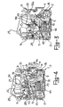
- the circuit breaker 1 further includes, within the body 8, an amperometer coil 44 of a large cross-section area wire which is accommodated on the core member 2, on the cheek piece 5 side, at the protected pole 14.
- the amperometer coil 44 has a respective pusher 45 adapted to engage with the lug 29 of the hooking lever 28 to release the moving contact holder assembly 26 on the occurrence of shorting currents, thereby causing the circuit breaker to break.
- the circuit breaker 1 also comprises a bimetal strip thermal relay 62 housed in the proximities of the amperometer coil 44 between the core member 2 and the cheek piece 5. It is active on the lever 28 to release the moving contact holder assembly 26.
- the circuit breaker 1 of this invention comprises, moreover, a thin wire voltmeter coil 46 which is housed in the body 8 on the core member 2, on the same side as the cheek piece 6, at the neutral pole 15.
- the voltmeter coil 46 has a respective pusher 47 adapted to engage with the lug 30 on the hooking lever to release the moving contact holder assembly 26 on the occurrence of a remote control command or by differential operation, thereby the circuit breaker is caused to break.
- the circuit breaker 1 is either manually operated, as by acting on the key capping, or automatically operated by energization of the amperometer and voltmeter coils and the thermal relay.
- attachment means 32 for spring mounting the moving contact 19 to the contact carrier body 31 will be next described.
- These attachment means 32 include a pin 48 jutting out of the contact carrier body 31 toward the cheek piece 5.
- the pin 48 engages in a hole 49 formed in a central portion 50 of the moving contact 19.
- the attachment means 32 further include a forked spring 51 having a base 52 and two prongs 53 and 54, with free ends 55 and 56.
- the forked spring 51 has a base 52 straddling the moving contact 19 at a forward active portion 57 thereof, its prongs 53 and 54 extending from opposed sides of the central portion 50 and wound into a spiral, with turns in opposite directions around the pin 48, and the free ends (( and 56 of the prongs 53 and 54 in engagement with a lug 58 formed on the contact carrier body 31.
- the spring 51 with its base 52, constantly urges the moving contact 19 to rotate around the pin 48 toward the fixed contact 18.
- a rearward tail portion 59 of the moving contact 19 engages with the lug 58 to stop rotation.
- Retainer means 60 are provided to retain the moving contact 19 axially on the pin 48. These retainer means 60 are comprised of an elevation 61 formed on the lug 58 of the contact carrier body 31, against which the free end 56 of the prong 54 of the spring 51 engages laterally.
- the attachment means 32 for spring mounting the moving contact 23 on the contact carrier body 31 are symmetrical of those described above for mounting the contact 19 relatively to the diaphragm 3, and accordingly, not described herein in detail.
- circuit breaker 1 Operation of the circuit breaker 1 will be described herein below with reference to a starting condition, shown in Figure 3, wherein the circuit breaker is in its make setting.
- the arc roots standing on the moving contacts will separate from the moving contacts and stand on their respective portions 38 and 39 of the crosspiece which overhang into the chambers 33 and 34 at the back of the "L".
- the arcs come to a final position, indicated at a2, which extends from the fixed contacts to the crosspiece.
- the moving contacts On the arcs moving into their final positions a2, the moving contacts become released by the action of the electric arc, and accordingly unaffected by further cratering actions. These will in fact appear, at least before the arc is extinguished on the current half-wave going through zero on the crosspiece, on which they bear no harmful influence.
- the circuit breaker 1 according to the invention has been provided with an electric arc change-over device effective to switch the arc from the moving contacts to an inert inoperative member, the crosspiece, with consequent increased life of the moving contacts.
- circuit breaker disclosed hereinabove may be in many ways altered and modified by a skilled person in order to meet specific contingent requirements within the protection scope of the invention as set forth in the appended claims.
Landscapes
- Breakers (AREA)
- Driving Mechanisms And Operating Circuits Of Arc-Extinguishing High-Tension Switches (AREA)
- Current-Collector Devices For Electrically Propelled Vehicles (AREA)
- Keying Circuit Devices (AREA)
- Electrical Discharge Machining, Electrochemical Machining, And Combined Machining (AREA)
- Emergency Protection Circuit Devices (AREA)
- Arc-Extinguishing Devices That Are Switches (AREA)
Priority Applications (1)
| Application Number | Priority Date | Filing Date | Title |
|---|---|---|---|
| AT87830216T ATE93650T1 (de) | 1986-08-04 | 1987-06-09 | Doppelpoliger schalter fuer elektrische einrichtungen im zivilen bereich, mit einer lichtbogenkommutierungseinrichtung. |
Applications Claiming Priority (2)
| Application Number | Priority Date | Filing Date | Title |
|---|---|---|---|
| IT8622748U IT207988Z2 (it) | 1986-08-04 | 1986-08-04 | Interruttore bipolare di apparecchiature elettriche di serie civili, con dispositivo di commutazione dell'arco elettrico. |
| IT2274886U | 1986-08-04 |
Publications (3)
| Publication Number | Publication Date |
|---|---|
| EP0255992A2 true EP0255992A2 (de) | 1988-02-17 |
| EP0255992A3 EP0255992A3 (en) | 1988-09-21 |
| EP0255992B1 EP0255992B1 (de) | 1993-08-25 |
Family
ID=11199992
Family Applications (1)
| Application Number | Title | Priority Date | Filing Date |
|---|---|---|---|
| EP87830216A Expired - Lifetime EP0255992B1 (de) | 1986-08-04 | 1987-06-09 | Doppelpoliger Schalter für elektrische Einrichtungen im zivilen Bereich, mit einer Lichtbogenkommutierungseinrichtung |
Country Status (6)
| Country | Link |
|---|---|
| EP (1) | EP0255992B1 (de) |
| AT (1) | ATE93650T1 (de) |
| BR (1) | BR6701521U (de) |
| DE (1) | DE3787136D1 (de) |
| ES (1) | ES2044973T3 (de) |
| IT (1) | IT207988Z2 (de) |
Cited By (3)
| Publication number | Priority date | Publication date | Assignee | Title |
|---|---|---|---|---|
| EP0403358A1 (de) * | 1989-06-16 | 1990-12-19 | Hager Electro S.A. | Null- und Phasenschalter |
| EP0780861A1 (de) * | 1995-12-21 | 1997-06-25 | Schneider Electric Sa | Elektrisches Gerät mit Bogenkommutierung |
| WO2007130321A1 (en) * | 2006-05-01 | 2007-11-15 | Siemens Energy & Automation, Inc. | Devices, systems, and methods for shunting a circuit breaker |
Family Cites Families (5)
| Publication number | Priority date | Publication date | Assignee | Title |
|---|---|---|---|---|
| US1750298A (en) * | 1927-12-31 | 1930-03-11 | Westinghouse Electric & Mfg Co | Circuit breaker |
| GB478824A (en) * | 1936-08-20 | 1938-01-26 | Frank Whyman | Improvements in arc extinguishing devices for electric circuit interrupters |
| US2302551A (en) * | 1939-08-16 | 1942-11-17 | Square D Co | Circuit breaker |
| US2924752A (en) * | 1957-07-12 | 1960-02-09 | Ite Circuit Breaker Ltd | Combined circuit breaker and short circuiter |
| FR2485254A1 (fr) * | 1980-06-19 | 1981-12-24 | Merlin Gerin | Disjoncteur miniature unipolaire et neutre |
-
1986
- 1986-08-04 IT IT8622748U patent/IT207988Z2/it active
-
1987
- 1987-06-09 ES ES87830216T patent/ES2044973T3/es not_active Expired - Lifetime
- 1987-06-09 EP EP87830216A patent/EP0255992B1/de not_active Expired - Lifetime
- 1987-06-09 DE DE87830216T patent/DE3787136D1/de not_active Expired - Lifetime
- 1987-06-09 AT AT87830216T patent/ATE93650T1/de not_active IP Right Cessation
- 1987-08-03 BR BR6701521U patent/BR6701521U/pt not_active IP Right Cessation
Cited By (7)
| Publication number | Priority date | Publication date | Assignee | Title |
|---|---|---|---|---|
| EP0403358A1 (de) * | 1989-06-16 | 1990-12-19 | Hager Electro S.A. | Null- und Phasenschalter |
| FR2648614A1 (fr) * | 1989-06-16 | 1990-12-21 | Hager Electro | Disjoncteur phase et neutre |
| EP0780861A1 (de) * | 1995-12-21 | 1997-06-25 | Schneider Electric Sa | Elektrisches Gerät mit Bogenkommutierung |
| FR2742916A1 (fr) * | 1995-12-21 | 1997-06-27 | Schneider Electric Sa | Dispositif electrique a commutation d'arc |
| US5777286A (en) * | 1995-12-21 | 1998-07-07 | Schneider Electric Sa | Electric device having separable contacts with arc switching |
| WO2007130321A1 (en) * | 2006-05-01 | 2007-11-15 | Siemens Energy & Automation, Inc. | Devices, systems, and methods for shunting a circuit breaker |
| US7796369B2 (en) | 2006-05-01 | 2010-09-14 | Siemens Industry, Inc. | Devices, systems, and methods for shunting a circuit breaker |
Also Published As
| Publication number | Publication date |
|---|---|
| BR6701521U (pt) | 1988-04-26 |
| ES2044973T3 (es) | 1994-01-16 |
| EP0255992B1 (de) | 1993-08-25 |
| IT8622748V0 (it) | 1986-08-04 |
| EP0255992A3 (en) | 1988-09-21 |
| IT207988Z2 (it) | 1988-03-14 |
| DE3787136D1 (de) | 1993-09-30 |
| ATE93650T1 (de) | 1993-09-15 |
Similar Documents
| Publication | Publication Date | Title |
|---|---|---|
| EP0399282B1 (de) | Automatischer magneto-thermischer Schutzschalter mit hoher Ausschaltleistung | |
| US6864765B2 (en) | Circuit breaker | |
| AU668972B2 (en) | Circuit breaker with auxiliary switch actuated by cascaded actuating members | |
| US4679016A (en) | Interchangeable mechanism for molded case circuit breaker | |
| GB1535191A (en) | Sequential resetting ground fault circuit interrupter | |
| US5694101A (en) | Circuit breaker | |
| GB1534804A (en) | Electrical circuit breaker | |
| CA1041597A (en) | Two pole ground fault circuit protector | |
| KR102056642B1 (ko) | 차단기의 순시 트립 장치 | |
| US4962406A (en) | Compact DC/AC circuit breaker with common arc extinguishing capability | |
| US4181922A (en) | Circuit interrupter with improved adjustable trip unit | |
| EP0255955B1 (de) | Leistungstrennschalter | |
| EP0100367B1 (de) | Ausschalter | |
| US3869590A (en) | Double-pole tool handle switch | |
| US3938065A (en) | Push-button operated bipolar faulty current protective switch | |
| EP0255992B1 (de) | Doppelpoliger Schalter für elektrische Einrichtungen im zivilen Bereich, mit einer Lichtbogenkommutierungseinrichtung | |
| US3214537A (en) | Electrical circuit protector having auxiliary indicating switch contacts | |
| GB905772A (en) | Electric circuit breaker | |
| GB1442794A (en) | Circuit interrupter protective device | |
| US3419828A (en) | Means proportional to magnetic flux to bias electric switch contacts closed | |
| CA1068391A (en) | Circuit breaker with improved trip means having a high rating shunt trip | |
| NZ196894A (en) | Trippable contactor latch | |
| US3406361A (en) | Electromagnetic relay having parts retained by a one-piece spring clip which also provides armature bias | |
| US5485134A (en) | Auxiliary switch accessory module unit for high ampere-rated circuit breaker | |
| EP0259272A2 (de) | Schalter, vorzugsweise aber nicht ausschliesslich doppelpoliger Schalter, für Montage auf Rahmen geschlossener Gehäuse von elektrischen Einrichtungen im zivilen Bereich |
Legal Events
| Date | Code | Title | Description |
|---|---|---|---|
| PUAI | Public reference made under article 153(3) epc to a published international application that has entered the european phase |
Free format text: ORIGINAL CODE: 0009012 |
|
| AK | Designated contracting states |
Kind code of ref document: A2 Designated state(s): AT BE CH DE ES FR GB GR LI NL SE |
|
| PUAL | Search report despatched |
Free format text: ORIGINAL CODE: 0009013 |
|
| AK | Designated contracting states |
Kind code of ref document: A3 Designated state(s): AT BE CH DE ES FR GB GR LI NL SE |
|
| 17P | Request for examination filed |
Effective date: 19881020 |
|
| 17Q | First examination report despatched |
Effective date: 19910523 |
|
| GRAA | (expected) grant |
Free format text: ORIGINAL CODE: 0009210 |
|
| AK | Designated contracting states |
Kind code of ref document: B1 Designated state(s): AT BE CH DE ES FR GB GR LI NL SE |
|
| PG25 | Lapsed in a contracting state [announced via postgrant information from national office to epo] |
Ref country code: SE Effective date: 19930825 Ref country code: NL Effective date: 19930825 Ref country code: LI Effective date: 19930825 Ref country code: GR Free format text: LAPSE BECAUSE OF FAILURE TO SUBMIT A TRANSLATION OF THE DESCRIPTION OR TO PAY THE FEE WITHIN THE PRESCRIBED TIME-LIMIT Effective date: 19930825 Ref country code: DE Effective date: 19930825 Ref country code: CH Effective date: 19930825 Ref country code: AT Effective date: 19930825 |
|
| REF | Corresponds to: |
Ref document number: 93650 Country of ref document: AT Date of ref document: 19930915 Kind code of ref document: T |
|
| REF | Corresponds to: |
Ref document number: 3787136 Country of ref document: DE Date of ref document: 19930930 |
|
| REG | Reference to a national code |
Ref country code: CH Ref legal event code: PL |
|
| ET | Fr: translation filed | ||
| REG | Reference to a national code |
Ref country code: ES Ref legal event code: FG2A Ref document number: 2044973 Country of ref document: ES Kind code of ref document: T3 |
|
| NLV1 | Nl: lapsed or annulled due to failure to fulfill the requirements of art. 29p and 29m of the patents act | ||
| PG25 | Lapsed in a contracting state [announced via postgrant information from national office to epo] |
Ref country code: GB Effective date: 19940609 |
|
| PLBE | No opposition filed within time limit |
Free format text: ORIGINAL CODE: 0009261 |
|
| STAA | Information on the status of an ep patent application or granted ep patent |
Free format text: STATUS: NO OPPOSITION FILED WITHIN TIME LIMIT |
|
| 26N | No opposition filed | ||
| GBPC | Gb: european patent ceased through non-payment of renewal fee |
Effective date: 19940609 |
|
| PGFP | Annual fee paid to national office [announced via postgrant information from national office to epo] |
Ref country code: BE Payment date: 20050601 Year of fee payment: 19 |
|
| PGFP | Annual fee paid to national office [announced via postgrant information from national office to epo] |
Ref country code: ES Payment date: 20050609 Year of fee payment: 19 |
|
| PGFP | Annual fee paid to national office [announced via postgrant information from national office to epo] |
Ref country code: FR Payment date: 20050629 Year of fee payment: 19 |
|
| PG25 | Lapsed in a contracting state [announced via postgrant information from national office to epo] |
Ref country code: ES Free format text: LAPSE BECAUSE OF NON-PAYMENT OF DUE FEES Effective date: 20060610 |
|
| PG25 | Lapsed in a contracting state [announced via postgrant information from national office to epo] |
Ref country code: BE Free format text: LAPSE BECAUSE OF NON-PAYMENT OF DUE FEES Effective date: 20060630 |
|
| REG | Reference to a national code |
Ref country code: FR Ref legal event code: ST Effective date: 20070228 |
|
| REG | Reference to a national code |
Ref country code: ES Ref legal event code: FD2A Effective date: 20060610 |
|
| BERE | Be: lapsed |
Owner name: *BASSANI TICINO S.P.A. Effective date: 20060630 |
|
| PG25 | Lapsed in a contracting state [announced via postgrant information from national office to epo] |
Ref country code: FR Free format text: LAPSE BECAUSE OF NON-PAYMENT OF DUE FEES Effective date: 20060630 |