EP0256202A2 - Corps de couplage pour un dispositif thérapeutique utilisant des ondes de choc - Google Patents
Corps de couplage pour un dispositif thérapeutique utilisant des ondes de choc Download PDFInfo
- Publication number
- EP0256202A2 EP0256202A2 EP87101802A EP87101802A EP0256202A2 EP 0256202 A2 EP0256202 A2 EP 0256202A2 EP 87101802 A EP87101802 A EP 87101802A EP 87101802 A EP87101802 A EP 87101802A EP 0256202 A2 EP0256202 A2 EP 0256202A2
- Authority
- EP
- European Patent Office
- Prior art keywords
- shock wave
- coupling body
- wave sensor
- sensor
- body according
- Prior art date
- Legal status (The legal status is an assumption and is not a legal conclusion. Google has not performed a legal analysis and makes no representation as to the accuracy of the status listed.)
- Withdrawn
Links
Images

Classifications
-
- A—HUMAN NECESSITIES
- A61—MEDICAL OR VETERINARY SCIENCE; HYGIENE
- A61B—DIAGNOSIS; SURGERY; IDENTIFICATION
- A61B17/00—Surgical instruments, devices or methods
- A61B17/22—Implements for squeezing-off ulcers or the like on inner organs of the body; Implements for scraping-out cavities of body organs, e.g. bones; for invasive removal or destruction of calculus using mechanical vibrations; for removing obstructions in blood vessels, not otherwise provided for
- A61B17/225—Implements for squeezing-off ulcers or the like on inner organs of the body; Implements for scraping-out cavities of body organs, e.g. bones; for invasive removal or destruction of calculus using mechanical vibrations; for removing obstructions in blood vessels, not otherwise provided for for extracorporeal shock wave lithotripsy [ESWL], e.g. by using ultrasonic waves
- A61B17/2251—Implements for squeezing-off ulcers or the like on inner organs of the body; Implements for scraping-out cavities of body organs, e.g. bones; for invasive removal or destruction of calculus using mechanical vibrations; for removing obstructions in blood vessels, not otherwise provided for for extracorporeal shock wave lithotripsy [ESWL], e.g. by using ultrasonic waves characterised by coupling elements between the apparatus, e.g. shock wave apparatus or locating means, and the patient, e.g. details of bags, pressure control of bag on patient
-
- G—PHYSICS
- G01—MEASURING; TESTING
- G01H—MEASUREMENT OF MECHANICAL VIBRATIONS OR ULTRASONIC, SONIC OR INFRASONIC WAVES
- G01H3/00—Measuring characteristics of vibrations by using a detector in a fluid
- G01H3/005—Testing or calibrating of detectors covered by the subgroups of G01H3/00
-
- G—PHYSICS
- G10—MUSICAL INSTRUMENTS; ACOUSTICS
- G10K—SOUND-PRODUCING DEVICES; METHODS OR DEVICES FOR PROTECTING AGAINST, OR FOR DAMPING, NOISE OR OTHER ACOUSTIC WAVES IN GENERAL; ACOUSTICS NOT OTHERWISE PROVIDED FOR
- G10K11/00—Methods or devices for transmitting, conducting or directing sound in general; Methods or devices for protecting against, or for damping, noise or other acoustic waves in general
- G10K11/004—Mounting transducers, e.g. provided with mechanical moving or orienting device
-
- A—HUMAN NECESSITIES
- A61—MEDICAL OR VETERINARY SCIENCE; HYGIENE
- A61B—DIAGNOSIS; SURGERY; IDENTIFICATION
- A61B17/00—Surgical instruments, devices or methods
- A61B17/22—Implements for squeezing-off ulcers or the like on inner organs of the body; Implements for scraping-out cavities of body organs, e.g. bones; for invasive removal or destruction of calculus using mechanical vibrations; for removing obstructions in blood vessels, not otherwise provided for
- A61B17/225—Implements for squeezing-off ulcers or the like on inner organs of the body; Implements for scraping-out cavities of body organs, e.g. bones; for invasive removal or destruction of calculus using mechanical vibrations; for removing obstructions in blood vessels, not otherwise provided for for extracorporeal shock wave lithotripsy [ESWL], e.g. by using ultrasonic waves
- A61B17/2251—Implements for squeezing-off ulcers or the like on inner organs of the body; Implements for scraping-out cavities of body organs, e.g. bones; for invasive removal or destruction of calculus using mechanical vibrations; for removing obstructions in blood vessels, not otherwise provided for for extracorporeal shock wave lithotripsy [ESWL], e.g. by using ultrasonic waves characterised by coupling elements between the apparatus, e.g. shock wave apparatus or locating means, and the patient, e.g. details of bags, pressure control of bag on patient
- A61B2017/2253—Implements for squeezing-off ulcers or the like on inner organs of the body; Implements for scraping-out cavities of body organs, e.g. bones; for invasive removal or destruction of calculus using mechanical vibrations; for removing obstructions in blood vessels, not otherwise provided for for extracorporeal shock wave lithotripsy [ESWL], e.g. by using ultrasonic waves characterised by coupling elements between the apparatus, e.g. shock wave apparatus or locating means, and the patient, e.g. details of bags, pressure control of bag on patient using a coupling gel or liquid
-
- A—HUMAN NECESSITIES
- A61—MEDICAL OR VETERINARY SCIENCE; HYGIENE
- A61B—DIAGNOSIS; SURGERY; IDENTIFICATION
- A61B90/00—Instruments, implements or accessories specially adapted for surgery or diagnosis and not covered by any of the groups A61B1/00 - A61B50/00, e.g. for luxation treatment or for protecting wound edges
- A61B90/06—Measuring instruments not otherwise provided for
- A61B2090/064—Measuring instruments not otherwise provided for for measuring force, pressure or mechanical tension
Definitions
- the invention relates to a coupling body for coupling a shock wave, in particular for the transmission of shock waves from a shock wave source to a patient to be treated, the coupling body being formed from an elastic, dimensionally stable material with moist outer surfaces.
- a shock wave source e.g. B. a lithotripter for kidney stone destruction, in which a shock wave pulse is generated with the help of an electrical coil (see. DE-OS 33 28 051)
- checks of the function are appropriate from time to time. Such checks relate, for example, to the focus position, the pressure distribution or the pressure amplitude of the shock wave pulse. Such checks are regularly useful when using the shock wave source; however, they are also necessary for initial assembly, after modifications, for service or for repairs. If, for example, the means focusing the shock wave pulse (such as an acoustic lens or a reflector) is exchanged, it must be checked afterwards whether the focus position is identical to the situation before the exchange.
- the means focusing the shock wave pulse such as an acoustic lens or a reflector
- a shock wave sensor which can be used in particular for lithotripsy, is known from DE-OS 34 37 976.
- the invention is based on the consideration that both shock wave sensors, in particular electrical pressure measuring elements, as well as test means for functional testing Shock wave indicators come into question.
- a shock wave indicator in addition to the direct observation of the point of impact of the shock wave pulses, a subsequent evaluation, e.g. B. Estimation of the integrally received energy may be possible.
- the handling of the test equipment is important. A loss-free coupling that is as reproducible as possible in a defined geometry is also important.
- the object of the present invention is to design a coupling body of the type mentioned at the outset in such a way that a simple check of the function of the shock wave source is possible after the coupling.
- This object is achieved in that a shock wave sensor is included in the elastic, dimensionally stable material.
- the shock wave sensor which can preferably be designed as an electrical pressure measuring element but also as a shock wave indicator, is preferably embedded in a dimensionally stable hydrogel.
- all test equipment suitable for measuring a shock wave can be used as shock wave sensors, but in particular small electrical pressure sensors and small optical indicators.
- the coupling body has a suitable shape, such as. B. disc or block shape, and can be placed by means of a bracket in a defined relation to the shock wave source on the coupling surface.
- the advantage here is a good coupling of the shock wave pulse to the shock wave sensor.
- Handling in the review the lithotripter function consists essentially of moistening one side of the coupling body, attaching the coupling body to the shock wave source and measuring.
- the transparent hydrogel that is preferably used enables direct observation or even optical detection and evaluation of the front and / or back of a shock wave indicator used as a sensor without dismantling.
- a piezoelectric activated PVDF film as a shock wave sensor, artifacts caused by undesired movement of the measuring film are reduced.
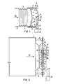
- a shock wave source 1 with its essential elements, namely with a shock wave generator 3, a lead section 5 with focusing means and a coupling-out membrane 7.
- a coupling body 11 which consists of an elastic, dimensionally stable material, in particular is made of the coupling-out membrane 7 a hydrogel with wet surfaces.
- a patient 13 is coupled to the free end face or coupling surface 12 of the concave-convex coupling body 11.
- a shock wave sensor 15 is contained in the coupling body 11.
- the shock wave sensor 15 is an electrical sensor, specifically a piezoceramic or a piezo crystal 17, which is connected to a measuring device 21 via a feed line 19.
- the piezo crystal 17 is preferably in the central region or in the middle of the coupling body 11, i. H. arranged on the central axis 22 of the shock wave source 1. It is also possible to provide a plurality of piezocrystals 17 next to one another, in the radial direction with respect to the central axis 22 or on a ring around the central axis 22.
- the function of the shock wave source 1 can be continuously checked with the aid of the piezo crystal 17 and the measuring device 21.
- the check consists, for example, in monitoring the correct (ie predetermined) pressure amplitude of the shock wave pulse at the location of the shock wave sensor 15.
- B known that given operating parameters of, for example, an operating voltage of 15 kV, a capacitor capacitance of 0.5 uF, a lead length of 20 cm, etc. at the location of the shock wave sensor 15 with proper operation and proper positioning, a predetermined amplitude of the shock wave pulse (reference value ) on must kick.
- the pressure amplitude determined by the shock wave sensor 15 deviates from the reference value by a predetermined percentage during the continuous therapy treatment, which can include up to 1000 shock wave pulses per patient, conclusions can be drawn about possible disturbances in the shock wave source 1.
- the determination of an excessive pressure amplitude can then be used to interrupt the therapy treatment, and a pressure amplitude which is too small can also give rise to the interruption of the therapy measure and subsequent checking of the system.
- the shock wave source 1 can be re-calibrated or adjusted after a possible repair or maintenance.
- an electromagnetic flat coil was used as the shock wave generator 3 and was exchanged for another coil during maintenance, there is the possibility that the center of the new coil is shifted slightly. Accordingly, when a shock wave pulse hits the shock wave sensor 15, the expected reference value will not occur, but a lower value. The coil can be readjusted until the specified reference value is reached. Then it is ensured that the shock wave source 1 has the same properties as before the maintenance or repair.
- the reference value that is used to reset the shock wave source 1 need not be the same as in the so-called "on-line" operation with the patient 13.
- the voltage value operating parameter can only be 12 kV instead of the 15 kV mentioned in the Therapy treatment amount or a range of z. B. drive through 12 kV to 20 kV.
- FIG. 2 the same parts are provided with the same reference symbols as in FIG. 1.
- the shock wave source 1 in turn consists of a shock wave generator 3, a lead section 5 with associated focusing means and a decoupling membrane 7.
- a perforated metal membrane 30 is clamped on the edge in an external holder 9 as a stabilizer.
- the metal membrane 30 has a recess 32 in its center, which runs coaxially to the center axis 22 of the shock wave source 1.
- the cutout 32 is spanned with a partially piezoelectric film, for example a PVDF film 34, which is piezoelectrically activated in its central region, that is to say is polarized.
- an annular lead electrode 36 is provided, which is arranged outside the polarized surface.
- the lead electrodes 36 are connected to lines 19 which lead to a measuring device 21.
- the PVDF film 34 and the ring-shaped discharge electrodes 36 form a shock wave sensor 15.
- Such a shock wave sensor 15 is described in detail in German patent application P 35 45 382.6, the content of which is to be part of the disclosure of the present description.
- the shock wave sensor 15 is embedded in a dimensionally stable, gel-like coupling body 11, which is held by the perforated metal membrane 30.
- the disk-shaped coupling body 11 rests on the decoupling membrane 7 with the support surface kept moist and free of air bubbles.
- the patient to be treated is coupled to the other (also kept moist) support surface.
- the shock wave sensor here comprises a large-area PVDF film 34 provided with cutouts, on each of which a polarization (i.e. piezoelectric activation) is carried out on predetermined small partial areas and a metal contact 40 is evaporated.
- the metal contacts 40 are each connected to a measuring device 21 via a line 19.
- the charge which arises on the activated sensor surface hit by a shock wave pulse is detected galvanically with the aid of the metal contacts 40, passed on galvanically through the lines 19 and in the associated measuring device 21 for a measured value, e.g. B. processed a voltage signal reflecting the temporal pressure curve.
- a measured value e.g. B. processed a voltage signal reflecting the temporal pressure curve.
- several measuring points lying next to one another or also in front of and behind one another are possible at the same time when using several PVDF foils.
- a gel-like, dimensionally stable coupling body 11 is designed as a "block"; that is, it has such dimensions that the focus F of a shock wave source 1 is still within the coupling body 11. This is indicated by the marginal rays 46, 48.
- the focus plane is close to the coupling surface 12 on the patient side.
- the shock wave indicator 50 consists, for example, of a round ceramic plate, which undergoes material removal under the action of shock waves, or a thin metal foil, especially lead foil, which deforms or bulges under the action of shock waves. Electrical connection lines are therefore not required here.
- the coupling body 11 is positioned in a holder 9 so that the factory-set values for the distance to the shock wave generator 3, for the size of the lead section 5, for the distance to the focusing means, etc. are met.
- the operating personnel can determine on the shock wave indicator 50, by visual inspection on the indicator 50 in the focus plane, whether there is mechanical deformation or ablation at the desired focus point, ie whether the focus F is actually at the predetermined point . If this is not the case, further testing and adjustment work must be carried out.
- the shock wave indicator 50 is preferably provided with a marking which is provided with sectors and circular rings similar to a (throwing or shooting) target. In this way, deviations in the focus position can be recorded quantitatively, which reduces the effort involved in the subsequent adjustment.
Landscapes
- Health & Medical Sciences (AREA)
- Surgery (AREA)
- Physics & Mathematics (AREA)
- Engineering & Computer Science (AREA)
- Life Sciences & Earth Sciences (AREA)
- Heart & Thoracic Surgery (AREA)
- General Health & Medical Sciences (AREA)
- Vascular Medicine (AREA)
- Orthopedic Medicine & Surgery (AREA)
- Biomedical Technology (AREA)
- General Physics & Mathematics (AREA)
- Medical Informatics (AREA)
- Molecular Biology (AREA)
- Animal Behavior & Ethology (AREA)
- Nuclear Medicine, Radiotherapy & Molecular Imaging (AREA)
- Public Health (AREA)
- Veterinary Medicine (AREA)
- Acoustics & Sound (AREA)
- Multimedia (AREA)
- Surgical Instruments (AREA)
- Electrotherapy Devices (AREA)
- Piezo-Electric Transducers For Audible Bands (AREA)
- Apparatuses For Generation Of Mechanical Vibrations (AREA)
Applications Claiming Priority (2)
| Application Number | Priority Date | Filing Date | Title |
|---|---|---|---|
| DE3627943 | 1986-08-18 | ||
| DE3627943 | 1986-08-18 |
Publications (2)
| Publication Number | Publication Date |
|---|---|
| EP0256202A2 true EP0256202A2 (fr) | 1988-02-24 |
| EP0256202A3 EP0256202A3 (fr) | 1989-01-04 |
Family
ID=6307613
Family Applications (1)
| Application Number | Title | Priority Date | Filing Date |
|---|---|---|---|
| EP87101802A Withdrawn EP0256202A3 (fr) | 1986-08-18 | 1987-02-10 | Corps de couplage pour un dispositif thérapeutique utilisant des ondes de choc |
Country Status (2)
| Country | Link |
|---|---|
| EP (1) | EP0256202A3 (fr) |
| JP (1) | JPS6351853A (fr) |
Cited By (20)
| Publication number | Priority date | Publication date | Assignee | Title |
|---|---|---|---|---|
| EP0381796A1 (fr) * | 1989-02-10 | 1990-08-16 | Siemens Aktiengesellschaft | Capteur ultrasonore |
| EP0407779A1 (fr) * | 1989-07-10 | 1991-01-16 | Richard Wolf GmbH | Couplage pour un lithotripteur |
| WO1991019459A1 (fr) * | 1990-06-20 | 1991-12-26 | Technomed International | Procede de controle de l'efficacite d'ondes de pression emises par un generateur d'ondes de pression |
| DE4132342A1 (de) * | 1991-09-27 | 1992-03-19 | Siemens Ag | Ultraschall-sensor mit gitterelektrode |
| DE4125621A1 (de) * | 1991-08-02 | 1993-02-04 | Manfred Dr Arnold | Ultraschall-vorlaufstreckenmaterial |
| WO1993007970A1 (fr) * | 1991-10-25 | 1993-04-29 | The Secretary Of State For Trade And Industry In Her Britannic Majesty's Government Of The United Kingdom Of Great Britain And Northern Ireland | Capteurs |
| FR2682868A1 (fr) * | 1991-10-24 | 1993-04-30 | Siemens Ag | Dispositif de therapie pour le traitement d'un etre vivant a l'aide d'ondes acoustiques focalisees. |
| US5601526A (en) * | 1991-12-20 | 1997-02-11 | Technomed Medical Systems | Ultrasound therapy apparatus delivering ultrasound waves having thermal and cavitation effects |
| DE19640050A1 (de) * | 1996-09-30 | 1998-04-02 | Siemens Ag | Vorrichtung und Verfahren zum Prüfen einer Quelle akustischer Wellen |
| DE19640051A1 (de) * | 1996-09-30 | 1998-04-02 | Siemens Ag | Vorrichtung und Verfahren zum Prüfen einer Quelle akustischer Wellen |
| DE10112458C1 (de) * | 2001-03-15 | 2002-10-10 | Hmt Ag | Verfahren und Vorrichtung zum Prüfen einer Quelle von akustischen Wellen |
| WO2003052373A3 (fr) * | 2001-12-19 | 2003-09-18 | Dornier Medtech Systems Gmbh | Controle et surveillance d'une source d'ondes de choc ou de pression |
| GB2397719A (en) * | 2003-01-23 | 2004-07-28 | Rolls Royce Plc | Ultrasonic transducer structure with performance monitoring arrangement |
| EP1479412A1 (fr) * | 2003-05-19 | 2004-11-24 | UST Inc. | Corps de couplage d'un hydrogel à forme géométrique pour le traitement par ultrasons focalisés à haute intensité |
| DE102004013092A1 (de) * | 2004-03-17 | 2005-10-06 | Dornier Medtech Systems Gmbh | Integrierter Drucksensor |
| EP1727125A1 (fr) * | 2004-11-26 | 2006-11-29 | HealthTronics Inc. | Méthode et dispositif pour régler un générateur d'ondes de choc |
| EP1727126A1 (fr) * | 2004-11-26 | 2006-11-29 | HealthTronics Inc. | Procédé et dispositif pour examiner la génération d'ondes de choc |
| DE10045847B4 (de) * | 1999-09-16 | 2008-11-06 | The Secretary Of State For Trade And Industry Of Her Majesty's Britannic Government | Kavitationssensor |
| US7955281B2 (en) | 2006-09-07 | 2011-06-07 | Nivasonix, Llc | External ultrasound lipoplasty |
| US8262591B2 (en) | 2006-09-07 | 2012-09-11 | Nivasonix, Llc | External ultrasound lipoplasty |
Families Citing this family (1)
| Publication number | Priority date | Publication date | Assignee | Title |
|---|---|---|---|---|
| US4955366A (en) * | 1987-11-27 | 1990-09-11 | Olympus Optical Co., Ltd. | Ultrasonic therapeutical apparatus |
Family Cites Families (4)
| Publication number | Priority date | Publication date | Assignee | Title |
|---|---|---|---|---|
| US4475376A (en) * | 1982-12-01 | 1984-10-09 | Advanced Technology Laboratories, Inc. | Apparatus for testing ultrasonic transducers |
| DE3429939A1 (de) * | 1984-08-14 | 1986-02-20 | Siemens AG, 1000 Berlin und 8000 München | Ultraschall-vorlaufstrecke |
| DE3437976A1 (de) * | 1984-10-17 | 1986-04-17 | Dornier System Gmbh, 7990 Friedrichshafen | Stosswellensensor |
| DE3503688A1 (de) * | 1985-02-04 | 1986-08-07 | Siemens AG, 1000 Berlin und 8000 München | Sicherheitseinrichtung fuer einen stosswellengenerator |
-
1987
- 1987-02-10 EP EP87101802A patent/EP0256202A3/fr not_active Withdrawn
- 1987-08-17 JP JP62204942A patent/JPS6351853A/ja active Pending
Cited By (28)
| Publication number | Priority date | Publication date | Assignee | Title |
|---|---|---|---|---|
| EP0381796A1 (fr) * | 1989-02-10 | 1990-08-16 | Siemens Aktiengesellschaft | Capteur ultrasonore |
| US5056069A (en) * | 1989-02-10 | 1991-10-08 | Siemens Aktiengesellschaft | Ultrasonic sensor |
| EP0407779A1 (fr) * | 1989-07-10 | 1991-01-16 | Richard Wolf GmbH | Couplage pour un lithotripteur |
| WO1991019459A1 (fr) * | 1990-06-20 | 1991-12-26 | Technomed International | Procede de controle de l'efficacite d'ondes de pression emises par un generateur d'ondes de pression |
| FR2663531A1 (fr) * | 1990-06-20 | 1991-12-27 | Technomed Int Sa | Procede de controle de l'efficacite d'ondes de pression emises par un generateur d'ondes de pression, des procedes de reglage en comportant application, ainsi qu'un appareil de controle d'efficacite d'ondes de pression, pour sa mise en óoeuvre. |
| DE4125621A1 (de) * | 1991-08-02 | 1993-02-04 | Manfred Dr Arnold | Ultraschall-vorlaufstreckenmaterial |
| DE4132342A1 (de) * | 1991-09-27 | 1992-03-19 | Siemens Ag | Ultraschall-sensor mit gitterelektrode |
| FR2682868A1 (fr) * | 1991-10-24 | 1993-04-30 | Siemens Ag | Dispositif de therapie pour le traitement d'un etre vivant a l'aide d'ondes acoustiques focalisees. |
| WO1993007970A1 (fr) * | 1991-10-25 | 1993-04-29 | The Secretary Of State For Trade And Industry In Her Britannic Majesty's Government Of The United Kingdom Of Great Britain And Northern Ireland | Capteurs |
| US5601526A (en) * | 1991-12-20 | 1997-02-11 | Technomed Medical Systems | Ultrasound therapy apparatus delivering ultrasound waves having thermal and cavitation effects |
| DE19640050A1 (de) * | 1996-09-30 | 1998-04-02 | Siemens Ag | Vorrichtung und Verfahren zum Prüfen einer Quelle akustischer Wellen |
| DE19640051A1 (de) * | 1996-09-30 | 1998-04-02 | Siemens Ag | Vorrichtung und Verfahren zum Prüfen einer Quelle akustischer Wellen |
| DE19640050C2 (de) * | 1996-09-30 | 2000-02-17 | Siemens Ag | Vorrichtung und Verfahren zum Prüfen einer Quelle akustischer Wellen |
| DE19640051C2 (de) * | 1996-09-30 | 2000-03-09 | Siemens Ag | Vorrichtung und Verfahren zum Prüfen einer Quelle akustischer Wellen |
| DE10045847B4 (de) * | 1999-09-16 | 2008-11-06 | The Secretary Of State For Trade And Industry Of Her Majesty's Britannic Government | Kavitationssensor |
| DE10112458C1 (de) * | 2001-03-15 | 2002-10-10 | Hmt Ag | Verfahren und Vorrichtung zum Prüfen einer Quelle von akustischen Wellen |
| WO2003052373A3 (fr) * | 2001-12-19 | 2003-09-18 | Dornier Medtech Systems Gmbh | Controle et surveillance d'une source d'ondes de choc ou de pression |
| GB2397719A (en) * | 2003-01-23 | 2004-07-28 | Rolls Royce Plc | Ultrasonic transducer structure with performance monitoring arrangement |
| GB2397719B (en) * | 2003-01-23 | 2006-04-19 | Rolls Royce Plc | Ultrasonic transudcer structures |
| US7069786B2 (en) | 2003-01-23 | 2006-07-04 | Rolls-Royce Plc | Ultrasonic transducer structures |
| EP1440738A3 (fr) * | 2003-01-23 | 2008-06-11 | ROLLS-ROYCE plc | Procédé de suivi du fonctionnement d'un transducteur ultrasonore |
| EP1479412A1 (fr) * | 2003-05-19 | 2004-11-24 | UST Inc. | Corps de couplage d'un hydrogel à forme géométrique pour le traitement par ultrasons focalisés à haute intensité |
| DE102004013092A1 (de) * | 2004-03-17 | 2005-10-06 | Dornier Medtech Systems Gmbh | Integrierter Drucksensor |
| DE102004013092B4 (de) * | 2004-03-17 | 2007-09-27 | Dornier Medtech Systems Gmbh | Integrierter Drucksensor |
| EP1727125A1 (fr) * | 2004-11-26 | 2006-11-29 | HealthTronics Inc. | Méthode et dispositif pour régler un générateur d'ondes de choc |
| EP1727126A1 (fr) * | 2004-11-26 | 2006-11-29 | HealthTronics Inc. | Procédé et dispositif pour examiner la génération d'ondes de choc |
| US7955281B2 (en) | 2006-09-07 | 2011-06-07 | Nivasonix, Llc | External ultrasound lipoplasty |
| US8262591B2 (en) | 2006-09-07 | 2012-09-11 | Nivasonix, Llc | External ultrasound lipoplasty |
Also Published As
| Publication number | Publication date |
|---|---|
| EP0256202A3 (fr) | 1989-01-04 |
| JPS6351853A (ja) | 1988-03-04 |
Similar Documents
| Publication | Publication Date | Title |
|---|---|---|
| EP0256202A2 (fr) | Corps de couplage pour un dispositif thérapeutique utilisant des ondes de choc | |
| DE3536271C2 (fr) | ||
| DE3543867C3 (de) | Vorrichtung zur räumlichen Ortung und zur Zerstörung von Konkrementen in Körperhöhlen | |
| DE2617779C2 (de) | Perkussionsinstrument für Diagnose- und Prüfzwecke | |
| DE4241161A1 (de) | Akustische Therapieeinrichtung | |
| DE3623614A1 (de) | Koordinatenmessgeraet mit einem tastkopf vom schaltenden typ | |
| DE2534207A1 (de) | Verfahren zum pruefen und messen von oberflaecheneigenschaften fester koerper, sowie einrichtung zur durchfuehrung des verfahrens | |
| DE3545381C2 (de) | Ultraschallwandler zur Messung der Schalleistung eines fokussierten Ultraschallfeldes | |
| EP0483603A2 (fr) | Source d'impulsions de pression | |
| EP2057960B1 (fr) | Dispositif dentaire à ultrasons et procédé de fonctionnement d'un dispositif dentaire à ultrasons | |
| DE3507577A1 (de) | Druckwellen-wandler | |
| EP0267475B1 (fr) | Capteur d'ultrasons | |
| DE8622086U1 (de) | Ankoppelkörper für eine Stoßwellen-Therapieeinrichtung | |
| DE102014112368A1 (de) | Messvorrichtung zum Charakterisieren eines Prüflings mittels Ultraschall | |
| DE4119147A1 (de) | Nachweisgeraet fuer aktiv abstrahlende flaechen von ultraschall-schwingern | |
| DE19728718C2 (de) | Vorrichtung zur Erzeugung fokussierter akustischer Wellen | |
| DE19640050C2 (de) | Vorrichtung und Verfahren zum Prüfen einer Quelle akustischer Wellen | |
| DE69922205T2 (de) | Verfahren und vorrichtung zur oberflächenprüfung | |
| DD284388A7 (de) | Tastsonde fuer ambulante schwingungsmessungen | |
| DE102004036526B4 (de) | Stoßwellenquelle und Stoßwellenbehandlungsgerät | |
| DE8622092U1 (de) | Sensor für die Erfassung von Stoßwellenimpulsen | |
| WO2023280905A1 (fr) | Générateur d'ultrasons d'alimentation en énergie électrique pour fragmenter des calculs, dispositif de lithotripsie, système de lithotripsie et procédé d'identification d'une sonotrode | |
| DE8809251U1 (de) | Einrichtung zur Behandlung von Proben mit in einem Fokus zusammenlaufenden Stoßwellen | |
| DE1473399A1 (de) | Verfahren zur Feststellung von Abweichungen vom Steigungswinkel einer geraden Linie | |
| DE102007055583A1 (de) | Zahnärztliches Ultraschallinstrument und Verfahren zum Betrieb eines zahnärztlichen Ultraschallinstruments |
Legal Events
| Date | Code | Title | Description |
|---|---|---|---|
| PUAI | Public reference made under article 153(3) epc to a published international application that has entered the european phase |
Free format text: ORIGINAL CODE: 0009012 |
|
| AK | Designated contracting states |
Kind code of ref document: A2 Designated state(s): DE FR GB NL |
|
| PUAL | Search report despatched |
Free format text: ORIGINAL CODE: 0009013 |
|
| AK | Designated contracting states |
Kind code of ref document: A3 Designated state(s): DE FR GB NL |
|
| 17P | Request for examination filed |
Effective date: 19890126 |
|
| 17Q | First examination report despatched |
Effective date: 19901008 |
|
| STAA | Information on the status of an ep patent application or granted ep patent |
Free format text: STATUS: THE APPLICATION IS DEEMED TO BE WITHDRAWN |
|
| 18D | Application deemed to be withdrawn |
Effective date: 19910419 |
|
| RIN1 | Information on inventor provided before grant (corrected) |
Inventor name: REICHENBERGER, HELMUT, DR. |